EP0810574A1 - Dispositif de présentation d'affichages publicitaires en papier ou autre matériaux - Google Patents
Dispositif de présentation d'affichages publicitaires en papier ou autre matériaux Download PDFInfo
- Publication number
- EP0810574A1 EP0810574A1 EP97108464A EP97108464A EP0810574A1 EP 0810574 A1 EP0810574 A1 EP 0810574A1 EP 97108464 A EP97108464 A EP 97108464A EP 97108464 A EP97108464 A EP 97108464A EP 0810574 A1 EP0810574 A1 EP 0810574A1
- Authority
- EP
- European Patent Office
- Prior art keywords
- posters
- poster
- sequence
- print media
- presentation
- Prior art date
- Legal status (The legal status is an assumption and is not a legal conclusion. Google has not performed a legal analysis and makes no representation as to the accuracy of the status listed.)
- Withdrawn
Links
- 239000000969 carrier Substances 0.000 title claims abstract description 4
- 230000006870 function Effects 0.000 claims description 27
- 238000012544 monitoring process Methods 0.000 claims description 7
- 241000233805 Phoenix Species 0.000 claims description 5
- 230000003442 weekly effect Effects 0.000 claims description 5
- 230000007257 malfunction Effects 0.000 claims description 4
- 238000013523 data management Methods 0.000 claims 1
- 238000000034 method Methods 0.000 description 8
- 230000005540 biological transmission Effects 0.000 description 7
- 238000004804 winding Methods 0.000 description 7
- 239000011888 foil Substances 0.000 description 5
- 229910052751 metal Inorganic materials 0.000 description 5
- 239000002184 metal Substances 0.000 description 5
- 238000006243 chemical reaction Methods 0.000 description 4
- 239000003550 marker Substances 0.000 description 4
- 241000859095 Bero Species 0.000 description 3
- 238000013461 design Methods 0.000 description 3
- 239000000872 buffer Substances 0.000 description 2
- 238000012937 correction Methods 0.000 description 2
- 238000010586 diagram Methods 0.000 description 2
- 238000010438 heat treatment Methods 0.000 description 2
- 238000004519 manufacturing process Methods 0.000 description 2
- 230000005236 sound signal Effects 0.000 description 2
- 238000012360 testing method Methods 0.000 description 2
- 238000005406 washing Methods 0.000 description 2
- WHXSMMKQMYFTQS-UHFFFAOYSA-N Lithium Chemical compound [Li] WHXSMMKQMYFTQS-UHFFFAOYSA-N 0.000 description 1
- 241000562569 Riodinidae Species 0.000 description 1
- 235000013334 alcoholic beverage Nutrition 0.000 description 1
- 229910052782 aluminium Inorganic materials 0.000 description 1
- XAGFODPZIPBFFR-UHFFFAOYSA-N aluminium Chemical compound [Al] XAGFODPZIPBFFR-UHFFFAOYSA-N 0.000 description 1
- 230000001174 ascending effect Effects 0.000 description 1
- 239000003795 chemical substances by application Substances 0.000 description 1
- 238000004891 communication Methods 0.000 description 1
- 238000001514 detection method Methods 0.000 description 1
- 230000001939 inductive effect Effects 0.000 description 1
- 238000003780 insertion Methods 0.000 description 1
- 230000037431 insertion Effects 0.000 description 1
- 238000009434 installation Methods 0.000 description 1
- 229910052744 lithium Inorganic materials 0.000 description 1
- 238000005259 measurement Methods 0.000 description 1
- 235000014594 pastries Nutrition 0.000 description 1
- 238000003825 pressing Methods 0.000 description 1
- 238000012545 processing Methods 0.000 description 1
- 229910000679 solder Inorganic materials 0.000 description 1
- 125000006850 spacer group Chemical group 0.000 description 1
- 230000036962 time dependent Effects 0.000 description 1
- 230000001960 triggered effect Effects 0.000 description 1
Images


Classifications
-
- G—PHYSICS
- G09—EDUCATION; CRYPTOGRAPHY; DISPLAY; ADVERTISING; SEALS
- G09F—DISPLAYING; ADVERTISING; SIGNS; LABELS OR NAME-PLATES; SEALS
- G09F11/00—Indicating arrangements for variable information in which the complete information is permanently attached to a movable support which brings it to the display position
- G09F11/24—Indicating arrangements for variable information in which the complete information is permanently attached to a movable support which brings it to the display position the advertising or display material forming part of a moving band, e.g. in the form of perforations, prints, or transparencies
- G09F11/29—Indicating arrangements for variable information in which the complete information is permanently attached to a movable support which brings it to the display position the advertising or display material forming part of a moving band, e.g. in the form of perforations, prints, or transparencies of a band other than endless
Definitions
- the invention relates to a device for presenting advertisements on paper or other print media, for example in the form of posters, these being arranged on a backlit backlit conveyor that moves in a mechanical device by at least one electric motor, from one roll to another Rolls up and vice versa, the device and the tape are arranged in a hinged housing, each of which has a print carrier, for example a print carrier, in at least one viewing window, via a microcomputer control in freely parameterizable presentation intervals a poster that presents.
- a print carrier for example a print carrier
- the object is achieved in that the presentation of the print carriers, in particular posters, is position-controlled, the positioning control being carried out by an electronic circuit which enables a selection of the poster shown in each case and its duration of presentation.
- an electronic circuit which enables a selection of the poster shown in each case and its duration of presentation.
- the electronic circuit is configured to be parameterizable by means of a chip or magnetic stripe card.
- a chip or magnetic stripe card programming via a laptop is also possible, in which case the transmission of programs using a chip or magnetic stripe card can be dispensed with.
- the chip or magnetic stripe card is particularly advantageous for programming a group of devices, for example for all devices in a specific advertising region, in selected cities, broadcasting regions of local radio stations, etc. Laptop programming is particularly suitable for Stand alone Programming.
- modern telephone operation is possible, via which remote parameterization (changing the programs) and malfunction detection of operating states of the advertising device can take place.
- the respective positioning of the posters behind the viewing window is advantageously carried out in two lanes via contactless switches, so-called Bero's.
- known markings for example aluminum strips, are applied to the carrier tape, which, in conjunction with the two tracks, enable the individual positions of the posters to be correctly coded.
- the switches can also use a time switch to detect when malfunctions occur, since then the reaching of the next position is not reported in the predetermined time. Then an alarm signal can be triggered, e.g. wireless, via signal lines or possibly about network feedback.
- the electronic circuit is designed to allow master-slave operation, e.g. be advantageously ensured that the presentation program change times are reliably observed even without a timer and a memory in each device. Like a program memory, a timer only needs to be present in the master device.
- one device of this device arrangement is designed as a master device and the other devices of the device arrangement are designed as slave devices.
- the other devices of the device arrangement are designed as slave devices.
- the changeable poster showcases that function as slave devices then receive from the ones that function as master devices Interchangeable poster showcase only commands of the form Fast forward a poster or Rewind a poster .
- a serial synchronization interface according to the RS485 standard can expediently be provided for the synchronization of the devices of the device arrangement.
- the microcontroller of the control device of each device of the device arrangement has a UART interface that with the laptop interface when the door of the respective device is open and with the laptop device when the door is closed is connected to the synchronization interface.
- the synchronization interface according to the RS485 standard can be an RS485 transceiver, the transmitter part of which can be switched with high impedance by software, a 2-pole relay which decouples the complete transceiver from the serial bus when the interchangeable poster display case in question is de-energized or works incorrectly, has a line terminating resistor of preferably 120 ohms that can be switched on or off by jumper, a BCD coding switch that specifies the slave address, and a 3-pin Phoenix connector for connection to a shielded twisted pair cable .
- the electronic control is advantageously memory-programmed and has a memory which makes it possible to present various print media, in particular posters, in accordance with the advertising schedule and freely parameterizable. Due to the programmability, predefined display times of the posters as well as free sequences of the individual can Posters on each other, up to the depiction of a picture story, can be achieved.
- a sequence consists of any number of posters in succession on the carrier tape, with a differently adjustable display time being predeterminable for each poster of the sequence.
- the show times and show sequences may be advantageously designed such that they are in campaign form, e.g. over a weekly cycle and according to daily schedules. Then it is e.g. possible to present different posters in different sequences on working days and non-working days, in the morning or evening hours etc.
- a daily schedule consists of a sequence of sequences that can be predetermined as required and a campaign consists of a sequence of daily plans that can be predetermined as required.
- the device advantageously has an automatic position synchronization device.
- the device has manual buttons with which the carrier tape can be moved slowly as desired.
- the housing is advantageously designed in such a way that when it is opened it not only switches off the control in relation to the automatic mode, but also switches on the automatic mode when it is closed. This ensures that even volatile operating personnel do not forget to restart the device after a new loading of posters.
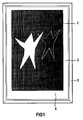
- 1 denotes the poster shown in the device or another printing medium, the edges of which are covered by the Passe Partout 2.
- the outside of the device is surrounded by a housing 3, which is formed in two parts and can be opened.
- the operating part of the device is located under area 4 of the Passe Partout 2 the electronic circuit, which is not accessible when the device is closed.
- the poster presented in each case is designated by 5.
- 8 and 13 designate buttons that enable slow counterclockwise or clockwise rotation when loading the device with new posters or perform other switching functions.
- 23 denotes a button for switching between manual and automatic operation.
- the buttons 8 and 13 for slow left and right rotation in the set-up mode can optionally also be arranged as buttons 9 on the side in the mechanical device.
- Below the control bar 7 is an area 6, behind which the drive elements for the two rollers are arranged, on which the tape is wound up or unwound. In a manner not shown separately, there is a circuit breaker in the usual design in the operating bar 7.
- FIG. 3 which shows a side view of the control part of the device, 15 denotes a circuit board on which electronic components such as resistors 20 and a microprocessor 22 are arranged.
- the terminal 17 for the electrical connection with the cable 18 and on the other hand there is a reader 19 for the chip or magnetic card 21 for programming.
- the circuit board 15 is arranged on spacer bolts 16, which keep it at a distance from the base plate of the mechanical device 14.
- circuit board 15 In addition to the electronic components shown, other electronic components are arranged on the circuit board 15, for example LEDs for control purposes, a switch which responds when the housing is opened and closed, etc.
- the electronic ones Circuitry is advantageously implemented by a program that can run under Windows. This results in an advantageously simple programmability.
- the device according to the invention explained below is an interchangeable poster showcase which contains a carrier film on which up to 16 posters are clamped.
- the carrier film is transported via two winding rolls, which are provided on the right and left edge of the housing.
- the carrier film has a beginning and an end, so it is not an endless belt.
- a metal foil is provided at the beginning and at the end of the carrier foil, which are glued to the carrier foil and thus mark the beginning and the end of the carrier foil.
- the center position of each of the 16 posters that can be provided on the carrier film is also identified by a metal film.
- the metal foils are queried via two inductive proximity switches.
- the carrier film is transported by switching a motor for clockwise or counterclockwise rotation on / off.
- the poster change is program-controlled.
- the interchangeable poster showcase there are two proximity switches which are arranged exactly one above the other at the lower edge of the carrier film shown in FIG.
- the lower proximity switch signals the stop position of each individual poster 1 to 16
- the upper proximity switch signals the start and end of the carrier film.
- the metal marks already mentioned are affixed to the carrier film in the form of metal films, by means of which the two proximity switches are activated.
- the starting position and the end position of the carrier film can be clearly distinguished from the individual poster positions and from one another.
- One by one The hole in the carrier film formed is always to the left of the starting position of the carrier film formed by the poster 1.
- the service position of the carrier film should also be identified by a metal film in the form of a Bero marker, and, as sketched in FIG. 4, not offset in the center but to the left, so that when changing tubes there is no need to use this Bero marker in manual mode to run over.
- the controller After closing the door of the removable poster showcase, the controller first moves to the starting position in order to achieve a tie between the internal poster counter and the actual poster stand. The selected program is then executed. This process, known as poster synchronization, takes place after every door closing, after a power failure and after a watchdog reset.
- the changeable poster showcase program In order to synchronize posters, the changeable poster showcase program generally rewinds the carrier film to the right until the upper contactless proximity switch has recognized the starting position. If, after manually opening the service opening, the operator forgets to manually move back to the start position before closing the door of the removable poster display case, no start position would be recognized without additional markers during the poster synchronization. The billboard was then moved to the right until it stopped. This may result in a film tear if the runtime monitoring does not stop the engine beforehand. Proper automatic operation would be impossible in any case.
- the hardware is designed in such a way that the use of non-contact switches in PNP or NPN design is possible via an assembly variant.
- the change of display cabinet firmware finds out the actual switching direction via a port input of the microcontroller (DIP switch).
- the control unit already shown in FIG. 3 is mounted on a mechanical device 14 in the form of an L plate in the lower part of the billboard display case.
- the main board 15 is spaced 16 parallel to the long leg of the L-plate.
- the connectors provided with the reader 19 are at a 90 degree angle to the main board 15 and protrude through corresponding holes in the short leg of the L-plate.
- the circuit board 15 with the electronic components and the connectors is mounted with the component side up on the L-plate. After loosening the fastening screws, the L-plate with the mounted board 15 can be pulled out of the removable poster showcase like a drawer.
- the component side of the circuit board 15 is at the top, so that cables can be connected without problems. In addition, 15 measurements are possible even with the circuit board installed.
- control unit In addition to the connectors mounted on the board 15, the control unit also contains additional, separately connected Control elements, namely the buttons 8, 13, 9 for scrolling to the left and scrolling to the right, and a door switch.
- buttons are connected to the board 15 via wires and Phoenix connectors.
- the buttons have the following functions:
- the door switch switches the removable poster showcase to automatic mode when the door is closed and to manual mode when the door is open.
- buttons for scrolling to the right or left are only in manual mode, i.e. with the door open, effective.
- manual mode the winding process stops when the button is pressed continuously when one of the two end positions is reached.
- the service position e.g. for a tube change, can only be achieved if the left hand button is released after the stop in the start position and pressed again.
- the change of the display case can be programmed either by serial data transmission via a connected laptop (RS232), by reading a chip card or by data transmission via a modem.
- connection option is provided which can be combined with a suitable modern.
- Non-multiplexed status signals (such as DTR) then ensure that the RxD / TxD lines are switched accordingly.
- the changeable poster showcase software allows free programmability of the poster display times, the assignment of posters to groups and the date / time-controlled selection of sequence processes.
- a group can of course include all 16 posters.
- the posters are rewound and rewound within a group, with the rewinding process being interrupted for a definable showing time for each poster.
- the sequence consists of only one poster.
- a still image is defined in this way. In this case, since no winding process is necessary within the sequence, there is no need to specify a display time for the still picture.
- the display time for the still picture is then identical to the sequence length defined in a daily schedule.
- the defined posters run forwards and backwards within a sequence, thus 7-8 - 9 - 10 - 11 - 10 - 9 - 8 - 7 - 8 - 9 - 10 etc. in the example explained above.
- a daily schedule for the operation of the billboard display cases is programmed by assigning individual sequences to times during a certain day.
- a specific lighting status of the removable poster display case can be programmed.
- a campaign can be programmed from several daily schedules by assigning the daily schedules to a specific calendar week, whereby optionally up to four date-related calendar days can be carried out.
- the sequences, the daily plans and the campaign are defined using a Windows 3.1 program. Attention was paid to functionality and ease of use. Furthermore the inputs checked for plausibility.
- a C ++ compiler serves as the programming language.
- a daily schedule file always contains a list with the names of the assigned sequence files, a campaign file, as well as always a list with the names of the assigned daily schedule files.
- the assignment is strictly bottom-up, ie the sequences must first have been defined before a day plan can be defined, and daily plans must be set up before the campaign can be defined.
- the assignment via file names in list fields presupposes the existence of the files used, since only existing files are listed for selection.
- the files remain independent of each other from the operating system perspective, so they can be renamed or deleted with the Windows File Manager. A programmed assignment can become invalid in this way if the user does not take the necessary care.
- a serial interface in accordance with the RS485 standard is provided for the syrichronization of several billboard display cases belonging to a device arrangement, which each billboard device has. Since the microcontroller used only has one UART interface, this is multiplexed, the UART interface being connected to the laptop interface when the removable display case door is open and to the RS485 serial synchronization interface when the removable display case door is closed.
- a front connector RS232 is assigned to the laptop interface, a Phoenix connector RS485 is assigned to the synchronization interface.
- the software of the device arrangement comprising this large number of change poster showcases enables the posters of the change poster showcases combined to form the device arrangement to be changed simultaneously or in succession.
- only the removable poster showcase which acts as the master device, needs to be programmed.
- the other billboard displays that function as slave devices then only receive commands of the form from the billboard showcase that functions as master devices Fast forward a poster or Rewind a poster .
- a BCD coding switch setting not equal to zero switches the relevant billboard display hardware to the slave operating state.
- the L-plate 14 To operate the BCD coding switch, the L-plate 14 must be pulled out of the interchangeable poster showcase, since the BCD coding switch is on the board 15. However, the switch position can be queried from the outside via the laptop.
- An 80C592 microcontroller is used as the computer core. This has an internal RAM with 512 bytes.
- a Dallas module DS1642 is used as memory for the billboard program and for the real-time clock. This block contains a RAM with 2KByte, a real time clock, a lithium battery with a lifespan of approx. 10 years and a voltage monitoring circuit.
- a 32 Kbyte EPROM (28-pin DIL, socket) serves as the program memory for the microcontroller.
- the power supply consists of a line filter, a transformer, rectifiers and voltage regulators.
- the transformer can be switched to 110 V operation via solder bridges. There is no mains fuse because the transformer has a thermal fuse that becomes high-resistance in the event of a short circuit or thermal overload.
- the transformer has a 30% reserve, which enables safe operation even at 70 degrees Celsius.
- the BCD coding switch determines the address of the connected billboard showcases in a chain in the course of the billboard display synchronization.
- the data transmission between the master device and the slave devices takes place via a serial point-to-point connection according to the RS485 standard, whereby no star-shaped wiring is provided.
- Switch position 0 of the BCD coding switch defines the removable poster showcase as the master device.
- the changeable poster showcase will then supply all connected slave devices with commands to fast forward and rewind.
- the BCD coding switch defines the corresponding billboard display as a slave device.
- the billboard display case prepared in this way does not need to be programmed; it receives all commands from the billboard display cabinet that functions as the master device.
- Each slave address may only be assigned once within the chain-shaped device arrangement. In the Domino mode, the slave devices of the chain-like device arrangement must also receive ascending addresses as seen from the master device.
- the changeable poster showcase reaches an error state that can only be exited by the conscious acknowledgment by an operator.
- a special sound signal that is only generated in this case and is designed as an intermittent beep with a frequency of approximately 4 Hz.
- the error signal is only generated when the door is open. If the door is closed without the error being acknowledged, the signal is switched off but is generated again the next time the door is opened.
- the error must be acknowledged by pressing both manual buttons 9 at the same time.
- the changeable poster showcase is then again in the normal operating state, that is, in the manual operating mode when the door is open.
- the sounder generates a single short beep as an OK message in the following operating states: after the power-on process, after successful transmission of the date / time via the serial interface, after successful transmission of the program via the serial interface, after successful reading of a program from a chip card, after successfully writing data to a chip card.
- the EPROM firmware was created in the C language and broken down into several modules or source files, as indicated below:
- the module Do the washing up contains a main state machine with four sub state machines.
- the sequence logic of the overall program is defined in the main state machine.
- the four sub-state machines control individual operating states, in particular the winding operation of the display case, as shown in FIG. 6.
- the module DATETIME contains all routines for date and time management as well as all routines for interpreting the billboard display program data. Daily schedules, sequences and show times are managed here.
- the module DEPREL contains all functions that are necessary for software debouncing of button and switch signals.
- the module PCLINK.C contains the functions required for serial communication with the PC or laptop.
- a command interpreter analyzes commands from the PC, calls up the desired functions and generates the acknowledgment bytes that are sent back to the PC.
- the functions for reading and setting the real-time clock RTC and for loading the billboard display program data are also available in this module.
- the module WPVHARD contains the routines that contain hardware-related functions. This includes routines for the output and input of single bytes via the port expansion logic, for reading DIP and BCD switches and for controlling the sounder or buzzer. This module also contains the Initsystem function, which initializes the billboard display hardware.
- the module CHIPCARD contains all functions for writing and reading the SLE4418 chip card.
- the module CONVERT contains all format conversion functions such as WORD byte conversions, byte ASCII conversions and byte BCD conversions.
- the module V24DR51 and the associated include file V24DRIVE contain the functions for interrupt-driven operation of the RS232 interface.
- a send and a receive buffer are implemented.
- the module also contains functions for initializing the buffers and the baud rate and the interrupt service routine.
- the module TIMER is used to control time-dependent functions, such as runtime monitoring, debouncing and sound signal generation, with one hardware timer and several software timers derived from this being provided.
- the hardware timer runs in interrupt mode and triggers an interrupt every 20 ms.
- the interrupt service routine operates the software timers and reads out certain registers of the real-time clock in order to trigger certain actions every full second, minute or every full day.
- the required routines are in this module.
- the module DEFINES contains all define instructions and all type declarations, especially those relating to the program data structure, ie for the formats of the sequences, daily schedules etc.
- the example is valid for programming via the RS232 interface as well as via the chip card.
- the only difference is in the ISO header, where the chip card contains bytes that cannot be changed by the user.
- these bytes are also transmitted in order to achieve the greatest possible compatibility.
- the checksum is used to verify the program file.
- the creation date should offer the possibility of a subsequent check, especially for chip cards.
- the designation of the billboard display program can either include a user-defined identification number or any user-defined text, for example the designation of the location of the billboard display case.
- the starting addresses are pointers to the individual plans within the program, namely the sequence plans, the daily plans, the campaign. These pointers are necessary because the size of the plans is variable.
- parameters are used to control individual functions, e.g. synchronization, heating, etc.
- Each sequence is defined by a start poster number, a stop poster number, a parameter byte and a list of show times (in seconds).
- the sequence name entered in the Windows interface is reduced to a unique sequence number (0..x).
- the number of show times is determined by the start poster number and the stop poster number.
- the first show time is assigned to the start poster, the last show time to the stop poster.
- Functions can be assigned to the bits of the parameter byte, e.g. Lighting, synchronization or other.
- Each sequence defines the show times for a maximum of 16 posters.
- the display times of each poster in seconds are coded with two bytes and can be between 3 seconds and 32400 seconds.
- sequence plans (0 ... x) can be defined as long as the total program size is not exceeded. Often some of the sequences will only consist of one poster.
- a single daily schedule is not tied to a specific date or day of the week. In general, it specifies the times in hours and minutes, when that day should be switched to the different defined sequences and the lighting of the billboard display should be switched on or off.
- each individual daily schedule contains two independent lists with a maximum of 8 or 4 consecutive times, which are distributed over a day. Depending on the list, each time is assigned either a sequence number or a change of lighting. The following must apply within the lists: Time n + 1> time n If the first time in a list is greater than 00:00, the sequence or lighting status of the previous day is continued until the first definition.
- the daily plan name entered in the operating software or the Windows interface is reduced to a unique number (0..10).
- a daily schedule is valid for exactly 24 hours, from 0:00 a day to the end at 23:59:59.
- a daily schedule contains the number of sequences defined for this day and the number of lighting changes defined for this day.
- Each defined sequence is specified with its number (0..x) and its call time.
- a maximum of eight sequence operations can be defined per day.
- times are specified at which a change of lighting takes place.
- a maximum of four lighting changes per day can be defined.
- Sequence changes and lighting changes can be programmed independently of each other.
- the billboard display program will continue the last defined sequence of the previous calendar day until the first defined sequence set of the current daily schedule. The same applies to the change of light.
- Each daily schedule can accommodate a maximum of eight sequence changes and four additional lighting changes. As a rule, fewer lighting changes per day will be required.
- a maximum of eleven different daily schedules (0..10) can be defined.
- the campaign is defined by a weekly schedule and a list of a maximum of four special days.
- the weekly schedule contains a list of seven daily schedule numbers. Each number corresponds exactly to a daily schedule. An incomplete weekly schedule is not allowed.
- Each special day, if defined, contains the date for which it should apply in addition to the assigned daily schedule number.
- a day plan is assigned to a specific date or day of the week.
- the campaign can go on for as long as you like. There is no start date and no duration. Each calendar day of the current date is assigned to either one of the special days or one of the days of the week. As a result, the time of programming the billboard display is absolutely uncritical. In the worst case, one of the programmed special days has already passed. The program for this special day would then no longer be executed.
- the campaign can start on any date.
- Each day of the week (Monday to Sunday) and each defined special day is assigned a daily schedule number (0..10).
- the daily schedule with the programmed number is used according to the current date or day of the week.
- the duration of the campaign is unlimited.
Landscapes
- Physics & Mathematics (AREA)
- General Physics & Mathematics (AREA)
- Engineering & Computer Science (AREA)
- Theoretical Computer Science (AREA)
- Controls And Circuits For Display Device (AREA)
- Displays For Variable Information Using Movable Means (AREA)
Applications Claiming Priority (2)
| Application Number | Priority Date | Filing Date | Title |
|---|---|---|---|
| DE1996121560 DE19621560A1 (de) | 1996-05-29 | 1996-05-29 | Gerät zum Präsentieren von Werbeanzeigen auf Papier oder anderen Druckträgern |
| DE19621560 | 1996-05-29 |
Publications (1)
| Publication Number | Publication Date |
|---|---|
| EP0810574A1 true EP0810574A1 (fr) | 1997-12-03 |
Family
ID=7795598
Family Applications (1)
| Application Number | Title | Priority Date | Filing Date |
|---|---|---|---|
| EP97108464A Withdrawn EP0810574A1 (fr) | 1996-05-29 | 1997-05-26 | Dispositif de présentation d'affichages publicitaires en papier ou autre matériaux |
Country Status (2)
| Country | Link |
|---|---|
| EP (1) | EP0810574A1 (fr) |
| DE (1) | DE19621560A1 (fr) |
Cited By (2)
| Publication number | Priority date | Publication date | Assignee | Title |
|---|---|---|---|---|
| EP0921514A1 (fr) * | 1997-12-03 | 1999-06-09 | Siemens Aktiengesellschaft | Dispositif d'affichage de publicité sur support imprimé |
| WO2007079554A1 (fr) * | 2006-01-10 | 2007-07-19 | Open N.V. | Procédé et dispositif pour afficher des images |
Families Citing this family (4)
| Publication number | Priority date | Publication date | Assignee | Title |
|---|---|---|---|---|
| DE10144930A1 (de) * | 2001-09-12 | 2003-04-17 | Siemens Ag | Wechselplakatvitrine |
| DE10152599B4 (de) * | 2001-10-25 | 2008-07-17 | Ströer Out-of-Home Media AG | Steuereinrichtung für Plakatwechsler |
| DE10156819B4 (de) * | 2001-10-25 | 2009-06-25 | Ströer Out-of-Home Media AG | Plakatwechslersteuersystem |
| DE10213711A1 (de) * | 2002-03-27 | 2003-10-16 | Gerriets Gmbh | Vorrichtung zur Präsentation mehrerer wechselnder, großformatiger Werbeinformationen |
Citations (6)
| Publication number | Priority date | Publication date | Assignee | Title |
|---|---|---|---|---|
| CA1200012A (fr) * | 1983-05-25 | 1986-01-28 | Paul Isaacs | Systeme indicateur selectif de parcours ou de destination pour vehicule de transport en commun |
| DE3625969A1 (de) * | 1986-07-31 | 1988-02-11 | August Iffland | Durchlichtbarer werbetraeger |
| FR2612675A1 (fr) * | 1987-03-20 | 1988-09-23 | Giraud Mangin Maxime | Dispositif d'affichage pour la visualisation simultanee d'images et de textes associes |
| FR2629243A1 (fr) * | 1988-03-24 | 1989-09-29 | Blanc Roger | Edicule urbain pour affichage publicitaire |
| EP0402494A1 (fr) * | 1989-06-12 | 1990-12-19 | Innovative Technologies | Dispositif publicitaire |
| EP0521229A1 (fr) * | 1991-10-22 | 1993-01-07 | MECKIND srl | Dispositif pour l'affichage d'images illuminées par l'arrière, en particulier images publicitaires |
-
1996
- 1996-05-29 DE DE1996121560 patent/DE19621560A1/de not_active Withdrawn
-
1997
- 1997-05-26 EP EP97108464A patent/EP0810574A1/fr not_active Withdrawn
Patent Citations (6)
| Publication number | Priority date | Publication date | Assignee | Title |
|---|---|---|---|---|
| CA1200012A (fr) * | 1983-05-25 | 1986-01-28 | Paul Isaacs | Systeme indicateur selectif de parcours ou de destination pour vehicule de transport en commun |
| DE3625969A1 (de) * | 1986-07-31 | 1988-02-11 | August Iffland | Durchlichtbarer werbetraeger |
| FR2612675A1 (fr) * | 1987-03-20 | 1988-09-23 | Giraud Mangin Maxime | Dispositif d'affichage pour la visualisation simultanee d'images et de textes associes |
| FR2629243A1 (fr) * | 1988-03-24 | 1989-09-29 | Blanc Roger | Edicule urbain pour affichage publicitaire |
| EP0402494A1 (fr) * | 1989-06-12 | 1990-12-19 | Innovative Technologies | Dispositif publicitaire |
| EP0521229A1 (fr) * | 1991-10-22 | 1993-01-07 | MECKIND srl | Dispositif pour l'affichage d'images illuminées par l'arrière, en particulier images publicitaires |
Cited By (4)
| Publication number | Priority date | Publication date | Assignee | Title |
|---|---|---|---|---|
| EP0921514A1 (fr) * | 1997-12-03 | 1999-06-09 | Siemens Aktiengesellschaft | Dispositif d'affichage de publicité sur support imprimé |
| WO2007079554A1 (fr) * | 2006-01-10 | 2007-07-19 | Open N.V. | Procédé et dispositif pour afficher des images |
| BE1016936A5 (nl) * | 2006-01-10 | 2007-10-02 | Open Nv | Werkwijze en inrichting voor het tonen van afbeeldingen. |
| AU2007204611B2 (en) * | 2006-01-10 | 2010-06-17 | Open N.V. | Method and device for displaying images |
Also Published As
| Publication number | Publication date |
|---|---|
| DE19621560A1 (de) | 1997-12-04 |
Similar Documents
| Publication | Publication Date | Title |
|---|---|---|
| DE69232877T2 (de) | Verfahren zur Ermittlung der Adresse eines an einem Datenbus angeschlossenen Gerätes | |
| EP0001416B1 (fr) | Système électronique de contrôle d'un parc de stationnement | |
| DE2418766A1 (de) | Anlage zur abgabe von fluessigkeiten | |
| DE3783859T2 (de) | Fernsteuersystem fuer ein anzeigegeraet. | |
| EP2780767A1 (fr) | Système comportant un dispositif d'entraînement à moteur électrique pour meubles et un appareil informatique ; procédé destiné à établir une connexion de communication entre le dispositif d'entraînement à moteur électrique pour meubles et l'appareil informatique ; et un tel dispositif d'entraînement pour meubles | |
| EP0810574A1 (fr) | Dispositif de présentation d'affichages publicitaires en papier ou autre matériaux | |
| DE8808645U1 (de) | Anzeigeeinrichtung für Feuerlöscher | |
| EP0600268A1 (fr) | Dispositif de surveillance dans un métier textile | |
| DE69114682T2 (de) | Elektrisches Kontroll- und Steuerungssystem einer Funktionseinheit, insbesondere eines Hauses eines Gebäudes, eines Schiffes oder dergleichen. | |
| EP1293956B1 (fr) | Vitrine pour affiches changeables | |
| DE19747663A1 (de) | Vorrichtung zur Beschriftung von Markierungsschildern | |
| EP1326218A2 (fr) | Parcmètre | |
| EP0921514B1 (fr) | Dispositif d'affichage de publicité sur support imprimé | |
| DE19516418A1 (de) | Falzmaschinenverbund | |
| DE2444302A1 (de) | Schaltungsanordnung zum erfassen der individuellen arbeitszeit unter gleitzeitbedingungen | |
| DE19503732A1 (de) | Diebstahlsicherungsvorrichtung für elektrische Geräte und Maschinen | |
| DE1790008A1 (de) | Numerisch gesteuerte Verdrahtungseinrichtung | |
| DE19727395A1 (de) | Vorrichtung zur Aufzeichnung der Arbeitszeit von Kraftfahrern | |
| DE19801008C2 (de) | Handetikettiergerät mit selbsttätiger Preisumrechnungsfunktion | |
| DE920956C (de) | Elektrische Zaehl-, Anzeige- und Rufvorrichtung | |
| DE2708333C2 (de) | Kennungsgeber für Textübertragungsgeräte | |
| EP0857684A1 (fr) | Méthode et dispositif pour installer et entretenir les contrÔleurs d'installations d'ascenseurs | |
| DE428117C (de) | Schaltvorrichtung fuer elektrische Universal-Lichtreklame, deren Lampen mit je einemKontakt in einem Kontaktfeld verbunden sind und durch ein zwischen Kontaktfedern und einer festen Kontaktplatte gefuehrtes Jacquardband gesteuert werden | |
| AT232764B (de) | Vorrichtung zur Überwachung betrieblicher Arbeitsvorgänge | |
| DE29609743U1 (de) | Vorrichtung zum Erfassen von Arbeits- bzw. Anwesenheitszeiten von Personen |
Legal Events
| Date | Code | Title | Description |
|---|---|---|---|
| PUAI | Public reference made under article 153(3) epc to a published international application that has entered the european phase |
Free format text: ORIGINAL CODE: 0009012 |
|
| AK | Designated contracting states |
Kind code of ref document: A1 Designated state(s): BE DE FR GB LU NL |
|
| 17P | Request for examination filed |
Effective date: 19980107 |
|
| 17Q | First examination report despatched |
Effective date: 19981201 |
|
| GRAG | Despatch of communication of intention to grant |
Free format text: ORIGINAL CODE: EPIDOS AGRA |
|
| STAA | Information on the status of an ep patent application or granted ep patent |
Free format text: STATUS: THE APPLICATION IS DEEMED TO BE WITHDRAWN |
|
| 18D | Application deemed to be withdrawn |
Effective date: 20001201 |