EP0810699B1 - Optische Relaisstation für Einzel- und Multiwellenlängenbetrieb mit Dispersionsentzerrung - Google Patents
Optische Relaisstation für Einzel- und Multiwellenlängenbetrieb mit Dispersionsentzerrung Download PDFInfo
- Publication number
- EP0810699B1 EP0810699B1 EP97303655A EP97303655A EP0810699B1 EP 0810699 B1 EP0810699 B1 EP 0810699B1 EP 97303655 A EP97303655 A EP 97303655A EP 97303655 A EP97303655 A EP 97303655A EP 0810699 B1 EP0810699 B1 EP 0810699B1
- Authority
- EP
- European Patent Office
- Prior art keywords
- grating
- wavelength
- optical
- dispersion
- fiber
- Prior art date
- Legal status (The legal status is an assumption and is not a legal conclusion. Google has not performed a legal analysis and makes no representation as to the accuracy of the status listed.)
- Expired - Lifetime
Links
Images
Classifications
-
- G—PHYSICS
- G02—OPTICS
- G02B—OPTICAL ELEMENTS, SYSTEMS OR APPARATUS
- G02B6/00—Light guides; Structural details of arrangements comprising light guides and other optical elements, e.g. couplings
- G02B6/24—Coupling light guides
- G02B6/26—Optical coupling means
- G02B6/28—Optical coupling means having data bus means, i.e. plural waveguides interconnected and providing an inherently bidirectional system by mixing and splitting signals
- G02B6/293—Optical coupling means having data bus means, i.e. plural waveguides interconnected and providing an inherently bidirectional system by mixing and splitting signals with wavelength selective means
- G02B6/29304—Optical coupling means having data bus means, i.e. plural waveguides interconnected and providing an inherently bidirectional system by mixing and splitting signals with wavelength selective means operating by diffraction, e.g. grating
- G02B6/29316—Light guides comprising a diffractive element, e.g. grating in or on the light guide such that diffracted light is confined in the light guide
- G02B6/29317—Light guides of the optical fibre type
-
- G—PHYSICS
- G02—OPTICS
- G02B—OPTICAL ELEMENTS, SYSTEMS OR APPARATUS
- G02B6/00—Light guides; Structural details of arrangements comprising light guides and other optical elements, e.g. couplings
- G02B6/24—Coupling light guides
- G02B6/26—Optical coupling means
- G02B6/28—Optical coupling means having data bus means, i.e. plural waveguides interconnected and providing an inherently bidirectional system by mixing and splitting signals
- G02B6/293—Optical coupling means having data bus means, i.e. plural waveguides interconnected and providing an inherently bidirectional system by mixing and splitting signals with wavelength selective means
- G02B6/29379—Optical coupling means having data bus means, i.e. plural waveguides interconnected and providing an inherently bidirectional system by mixing and splitting signals with wavelength selective means characterised by the function or use of the complete device
- G02B6/29392—Controlling dispersion
- G02B6/29394—Compensating wavelength dispersion
-
- H—ELECTRICITY
- H01—ELECTRIC ELEMENTS
- H01S—DEVICES USING THE PROCESS OF LIGHT AMPLIFICATION BY STIMULATED EMISSION OF RADIATION [LASER] TO AMPLIFY OR GENERATE LIGHT; DEVICES USING STIMULATED EMISSION OF ELECTROMAGNETIC RADIATION IN WAVE RANGES OTHER THAN OPTICAL
- H01S3/00—Lasers, i.e. devices using stimulated emission of electromagnetic radiation in the infrared, visible or ultraviolet wave range
- H01S3/05—Construction or shape of optical resonators; Accommodation of active medium therein; Shape of active medium
- H01S3/06—Construction or shape of active medium
- H01S3/063—Waveguide lasers, i.e. whereby the dimensions of the waveguide are of the order of the light wavelength
- H01S3/067—Fibre lasers
- H01S3/06754—Fibre amplifiers
- H01S3/06758—Tandem amplifiers
-
- H—ELECTRICITY
- H04—ELECTRIC COMMUNICATION TECHNIQUE
- H04B—TRANSMISSION
- H04B10/00—Transmission systems employing electromagnetic waves other than radio-waves, e.g. infrared, visible or ultraviolet light, or employing corpuscular radiation, e.g. quantum communication
- H04B10/25—Arrangements specific to fibre transmission
- H04B10/2507—Arrangements specific to fibre transmission for the reduction or elimination of distortion or dispersion
- H04B10/2513—Arrangements specific to fibre transmission for the reduction or elimination of distortion or dispersion due to chromatic dispersion
- H04B10/2519—Arrangements specific to fibre transmission for the reduction or elimination of distortion or dispersion due to chromatic dispersion using Bragg gratings
-
- H—ELECTRICITY
- H04—ELECTRIC COMMUNICATION TECHNIQUE
- H04B—TRANSMISSION
- H04B10/00—Transmission systems employing electromagnetic waves other than radio-waves, e.g. infrared, visible or ultraviolet light, or employing corpuscular radiation, e.g. quantum communication
- H04B10/29—Repeaters
- H04B10/291—Repeaters in which processing or amplification is carried out without conversion of the main signal from optical form
-
- H—ELECTRICITY
- H01—ELECTRIC ELEMENTS
- H01S—DEVICES USING THE PROCESS OF LIGHT AMPLIFICATION BY STIMULATED EMISSION OF RADIATION [LASER] TO AMPLIFY OR GENERATE LIGHT; DEVICES USING STIMULATED EMISSION OF ELECTROMAGNETIC RADIATION IN WAVE RANGES OTHER THAN OPTICAL
- H01S3/00—Lasers, i.e. devices using stimulated emission of electromagnetic radiation in the infrared, visible or ultraviolet wave range
- H01S3/05—Construction or shape of optical resonators; Accommodation of active medium therein; Shape of active medium
- H01S3/06—Construction or shape of active medium
- H01S3/063—Waveguide lasers, i.e. whereby the dimensions of the waveguide are of the order of the light wavelength
- H01S3/067—Fibre lasers
- H01S3/0675—Resonators including a grating structure, e.g. distributed Bragg reflectors [DBR] or distributed feedback [DFB] fibre lasers
Definitions
- This invention relates to optical repeaters for single- and multi-wavelength operation, with particular application to wavelength division multiplex (WDM) optical telecommunication systems operating at bit rates in the range from 2.5Gb/s to 10Gb/s per carrier wavelength.
- WDM wavelength division multiplex
- NDSF non-dispersion shifted fiber
- Dispersion compensation in the 1550nm wavelength region is an attractive way to overcome this constraint.
- Various schemes are known to have been suggested or employed for dispersion compensation.
- DCF dispersion compensating fiber
- Other compensators are known based on fibre gratings, optical interferometers, or cascades of birefringent optical fibers.
- a dispersion compensating element is used in combination with one or two erbium doped fiber amplifiers, each requiring a pump laser.
- the latter combination is conventionally used either in discrete or integrated form, with a dispersion compensating fiber. The result is expensive and large sized repeater equipment.
- an optical fiber grating as a dispersion equalizer instead of dispersion compensating fibre has the potential for lower cost, but the drawback of known dispersion equalizers based on grating systems is the narrow optical bandwidth and resultant high sensitivity for carrier frequency fluctuations.
- an optical fibre transmission system using a chirped Bragg reflector and directional coupler for dispersion equalization is described in U.S. Patent 4,953,939 entitled "Optical Fibre Transmission Systems" to Epworth. Epworth uses a piece of fibre in which reflective properties of the grating are graded along the length of the piece of fibre. Different sections of the piece of fibre reflect different optical frequencies and this system provides limited bandwidth.
- each optical fiber grating based dispersion equalizer requires an optical amplifier for loss compensation.
- the optical bandwidth of a chirped fiber grating is directly proportional to the length of the grating. Given a practical length limitation based upon grating stability and/or manufacturability, the desired optical bandwidth determines the grating chirp parameter, which in turn determines the amount of dispersion compensation from the fiber grating. In known systems, increased dispersion compensation can be achieved only at the expense of optical bandwidth for a given grating length.
- TAVERNER D ET AL: 'DISPERSION COMPENSATION OF 16PS PULSES OVER 100KM OF STEP-INDEX FIBRE USING CASCADED CHIRPED FIBRE GRATINGS' ELECTRONICS LETTERS, vol. 31, no. 12, 8 June 1995, pages 1004-1006 discloses a dispersion equalizer provided by first and second cascaded lengths of temperature chirped optical fibre grating coupled in parallel connection in first and second output ports of an optical coupler (4-port circulator), with both gratings being tuned to the same central wavelength.
- DE 195 16 439 A HITACHI LTD discloses an optical repeater comprising a dispersion equalizer coupled between first and second lengths of a fibre amplifier.
- the present invention seeks to provide an optical repeater for single- and multi-wavelength operation with dispersion equalization, which overcomes or avoids the above-mentioned problems.
- a dispersion equalizer for use with a signal carrier wavelength ⁇ c , the equalizer comprising first and second cascaded optical fibre branches coupled in parallel connection by first and second ports of an optical circulator, each branch comprising a respective length of optical fibre grating of different center wavelength reflection characteristics, a first of said gratings being chirped to provide reflection of a signal of wavelength greater than ⁇ c , and a second of said gratings being chirped to provide reflection of a signal of wavelength less than ⁇ c .
- an optical repeater comprising a dispersion equalizer as claimed in any of claims 1 to 6, wherein the cascaded branches are coupled between first and second lengths of a fibre amplifier.
- dispersion equalization is provided by two lengths of fiber grating that are cascaded so that the bandwidth is doubled relative to the same amount of dispersion compensation using a single grating approach.
- the insertion loss of the equalizer element is efficiently compensated by inserting it between two sections of a fiber amplifier which share a common pump laser.
- the optical repeater provides optical loss compensation and chromatic dispersion compensation, and the bandwidth is doubled relative to conventional systems using a grating for dispersion equalization.
- the fiber amplifier comprises first and second lengths of an erbium doped fiber, and both lengths of fiber are pumped by a single laser source.
- the system uses a single pumped optical amplifier, in place of discrete optical amplifiers associated with each grating. Because only one pump laser source is required, the cost is reduced.
- an optical repeater for multi-wavelength operation for a WDM system operating with a plurality of wavelengths, wherein each length of optical fiber grating comprises a plurality of grating elements coupled in series each designed to reflect one of the plurality of operating wavelengths. Each grating comprises a cascade of grating elements chirped for each of the wavelengths.
- an optical repeater for WDM operation is provided by connecting appropriately tuned fiber gratings in series.
- an optical repeater for cascaded dispersion compensation for 4 carrier wavelengths includes first and second cascaded optical fibre grating stages, each grating stage comprising four optical fiber grating elements in series. Each grating element is chirped for a specific one of the carrier wavelengths so that each grating element of the cascade is designed to reflect one of the four carrier wavelengths and transmit other wavelengths.
- an optical repeater providing dispersion equalization and loss compensation is provided, based on cascaded fiber gratings, which offers improved optical bandwidth, a reduction in size, and reduced cost compared to known systems.
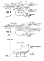
- An optical repeater 10 according to a first embodiment of the present invention is shown schematically in Figure 1 and comprises a single wavelength dispersion equalizer 12, which comprises a cascade of two optical fiber gratings 14 (FG1) and 16 (FG2) connected in parallel through an optical coupler, that is, coupled to two ports of a four port directional coupler 18.
- a single wavelength dispersion equalizer 12 which comprises a cascade of two optical fiber gratings 14 (FG1) and 16 (FG2) connected in parallel through an optical coupler, that is, coupled to two ports of a four port directional coupler 18.
- the dispersion equalizer 12 is coupled between sections of a conventional erbium doped fiber amplifier (EDFA), which is divided into first and second sections 20 (EDFA1) and 22 (EDFA2), comprising an optical fiber heavily doped with erbium ions to a concentration of typically 1500 to 2500 ppm.
- EDFA erbium doped fiber amplifier
- the first section 20 is 10 to 12 metres long and the second section 22 is 10 to 11 meters long. That is, a standard length of 20 to 25 meters of fibre is divided into two sections: the second part may be somewhat longer than the first part, i.e. by 1 to 2 meters, because it is pumped by a more attenuated pump signal.
- the two lengths 20 and 22 of erbium doped fiber are pumped by a single pump laser 24 using three wavelength selective couplers 26, 28, and 30 (WDM1, WDM2 and WDM3) as shown in Figure 1, to direct about 50% of the pump power into the first fiber section 20 (EDFA1), and about 50% into the second fiber section 22 (EDFA2).
- WDM1, WDM2 and WDM3 three wavelength selective couplers 26, 28, and 30 as shown in Figure 1, to direct about 50% of the pump power into the first fiber section 20 (EDFA1), and about 50% into the second fiber section 22 (EDFA2).
- an incoming optical signal from a preceding optical fiber span passes through a first optical isolator 32 (ISO1) through the first wavelength selective coupler 26 (WDM1) and into the first length of erbium doped fiber 20 (EDFA1).
- the signal passes through a second wavelength selective coupler 28 (WDM2) and enters the directional optical coupler 12 through a second optical isolator 34 (IS02) at port 1, is reflected at each of the dispersion gratings 14 and 16 at corresponding output ports 2 and 4, exits the coupler 12 from port 3, and enters the second length of erbium doped fiber 22 through another wavelength selective coupler 30 (WDM3), exiting through the repeater through another optical isolator 36 (ISO3).
- Each grating 14 and 16 is an in-fibre Bragg grating with linear chirp resulting in a linearly decreasing pitch imprinted along a piece of fibre.
- Grating 14 is imprinted along the entire length of the corresponding piece of fiber.
- the effective length of the fibre 3cm to 3.3cm, is the length of the in-fiber Bragg grating.
- the second fiber piece has a total length of 6cm to 6.6cm and grating 16 is imprinted only along the second half of this piece, so that the length of the fibre Bragg grating 16 is also 3cm to 3.3cm long.
- the signal carrier wavelength ⁇ s in the single wavelength scheme of Figure 1 corresponds to the central wavelength of the two branch equalizer ⁇ c as shown in Figure 3.
- the fibre grating 14 (FG1) is chirped to provide that the average product of its effective refractive index to the grating mechanical period corresponding to a wavelength ( ⁇ c - ⁇ /2)/2 where ⁇ represents the bandwidth of the two branch fiber grating equalizer.
- fiber grating 16 (FG2) is chirped to provide an average product of its effective refractive index to the grating mechanical period corresponding to a wavelength of ( ⁇ c + ⁇ /2)/2. Therefore, in the optical repeater according to a first embodiment of the present invention, two lengths of fiber grating are cascaded so that the bandwidth is doubled (see Figure 3) for the same amount of dispersion compensation, relative to a single grating approach.
- Both gratings 14 and 16 operate in reflection mode for the incoming optical signal, with means that shorter wavelengths within the signal spectral width travel further into the grating than longer wavelengths, if gratings operate in the 1530 to 1560nm region. As a result, the group delay between longer wavelengths and shorter wavelengths within the spectral width of the signal is compensated.
- the two band dispersion equalizer shown schematically in Figure 1 can tolerate carrier wavelength fluctuations of ⁇ - ⁇ s where ⁇ represents the optical bandwidth of the dispersion equalizer element 12, while ⁇ s represents the optical spectral width of the data signal. If the signal carrier wavelength becomes lower than the central wavelength of the two branch equalizer, fibre grating 14 (FG1) will take over the dispersion compensation function and if the signal carrier wavelength becomes higher than the central wavelength of the equalizer, fibre grating 16 (FG2) will take over the dispersion compensation function.
- the optical isolators 32, 34 and 36 (ISO1, ISO2 and IS03) are included to prevent backward reflected signals from influencing the operation of the preceding elements.
- Each isolator preferably has insertion losses lower than 0.5dB and backward attenuation higher than 30 dB.
- Conventional wavelength division multiplex couplers 26, 28 and 30 (WDM1, WDM2, WDM3) are used for pump injection into the optical fiber lengths 20 and 22.
- a 3dB directional coupler 12 is used for the two branch fibre grating.
- the pump signal by-passes the directional coupler 12 through which the signal passes, and the pump signal is diverted directly from the coupler 28 (WDM2) through to coupler 30 (WDM3).
- the optical repeater is capable of compensating both the losses and chromatic dispersion from a preceding optical fiber span with a maximum length of about 80 to 105km, and a total chromatic dispersion of 1700 to 1800 ps/nm.
- the total optical power of the pump was in the range 13 to 16 dBm at a central wavelength of 980nm.
- the total gain in the first and second lengths of the erbium doped fiber are in the range 27 to 33dB.
- the input signal was no lower than -15dBm at the carrier wavelength.
- the insertion loss of the dispersion equalizer element is efficiently compensated by inserting it between two sections of fibre amplifier, which preferably share a common pump laser.
- This scheme may be expanded for WDM operation, i.e. using multiple wavelengths, by connecting in series a plurality of appropriately tuned fiber gratings in each grating stage.
- optical repeater 100 for four wavelength operation is shown in Figure 2.
- This optical repeater 100 is similar to that shown in Figure 1, and like elements are referred to by the same reference numeral incremented by 100, for example dispersion equalizer 112 and first and second lengths of erbium doped fiber amplifier 120 and 122 pumped by a single common laser source 124.
- Wavelength selective couplers and optical isolators are provided similarly to those of the first embodiment.
- the optical repeater of the second embodiment differs from that of the first embodiment in that, instead of cascaded single gratings 14 and 16 in each branch as shown in Figure 1, each grating branch 114 and 116 comprises a series of four fiber gratings, so that there is effectively a cascade of four grating pairs, each grating pair being designed for a specific carrier wavelength.
- the operational principle for a four wavelength optical repeater is the same and for single wavelength repeater of the first embodiment, but there is wavelength selection within each fiber grating stage. Each fiber grating from each stage operates in the reflection regime for the corresponding carrier wavelength, while operating in the transmission regime for the other carrier wavelengths.
- gratings designated FG1a and FG2a are designed for a carrier wavelength ⁇ a
- gratings designated FG1b and FG2b are designed for wavelength ⁇ b
- gratings designated FG1c and FG2c are designed for wavelength ⁇ c
- gratings designated FG1d and FG2d are designed for wavelength ⁇ d .
- gratings FG1a, FG1b, FG1c and FG1d are chirped using the aforementioned methodology to match operating carrier wavelengths ( ⁇ a - ⁇ /2)/2, ( ⁇ b - ⁇ /2)/2, ( ⁇ c - ⁇ /2)/2, ( ⁇ d - ⁇ /2)/2, respectively.
- Fiber gratings FG2a, FG2b, FG2c and FG2d are chirped to match operating carrier wavelengths ( ⁇ a + ⁇ /2)/2, ( ⁇ b + ⁇ /2)/2, ( ⁇ c + ⁇ /2)/2, ( ⁇ d + ⁇ /2)/2 respectively.
- carrier wavelengths should be no less than 3nm apart from each other.
- the optical equalizer operates independently for each carrier wavelength and there is negligible mutual interaction between particular carrier wavelength and gratings that do not belong to the group that support this wavelength.
- the total gain of the system shown in Figure 2 is 32dBm.
- fiber dispersion gratings are provided with a linear chirp with an average pitch equal to the desired Bragg resonant centre wavelength, divided by twice the effective refractive index of the signal carrier optical waveguide.
- the chirp constant of the grating is in the range 0.23nm, to 0.25nm.
- the length of each of the gratings, except FG2 and FG2-a, is 3.0cm to 3.3cm, with the optical bandwidth of 0.25nm to 0.27nm.
- the lengths of sections forming FG2 and FG2-a are 6.0cm to 6.6cm where the first half of this length is regular fiber, without a grating, and the second half of this length represents the grating imprinted in the fiber.
- the total optical bandwidth of the two branch fiber grating couple is 0.42nm to 0.47nm.
- optical repeaters described above and shown schematically in Figures 1 and 2 compensate both losses and chromatic dispersion from a preceding optical fiber span, having e.g. a length of 80km to 105km, and a total chromatic dispersion of 1700 to 1800 ps/nm.
- the total optical power of the pump is in the range from 13-16 dBm at a central wavelength of 980nm.
- the total gain in EDFA1 and EDFA2 is in the range from 27dB to 33 dB.
- the input signal level is no lower than -15dBm at the carrier wavelength.
- an optical repeater for single and multi-wavelength operation comprising dispersion equalization provided by at least two cascaded lengths of optical fiber grating coupled in parallel connection in first and second ports of an optical coupler, coupled to first and second lengths of a fibre amplifier and a common pump source, which spreads the narrow optical bandwidth of a dispersion compensator based on optical fiber gratings, and compensates for optical losses induced by the dispersion compensator in a compact and efficient arrangement using a EDFA with single pump source.
Landscapes
- Physics & Mathematics (AREA)
- Electromagnetism (AREA)
- Optics & Photonics (AREA)
- Engineering & Computer Science (AREA)
- Computer Networks & Wireless Communication (AREA)
- General Physics & Mathematics (AREA)
- Signal Processing (AREA)
- Chemical & Material Sciences (AREA)
- Dispersion Chemistry (AREA)
- Plasma & Fusion (AREA)
- Optical Communication System (AREA)
- Lasers (AREA)
- Light Guides In General And Applications Therefor (AREA)
- Cable Transmission Systems, Equalization Of Radio And Reduction Of Echo (AREA)
Claims (9)
- Dispersionsentzerrer zur Verwendung mit einer Signalträger-Wellenlängeλ c , wobei der Entzerrer erste und zweite kaskadierte Lichtleitfaser-Zweige (14, 16) umfaßt, die in Parallelverbindung durch erste und zweite Anschlüsse eines optischen Zirkulators (12) gekoppelt sind, wobei jeder Zweig (14, 16) einen jeweiligen Längenabschnitt eines Lichtleitfaser-Gitters (FG1, FG2) mit unterschiedlichen Mitten-Wellenlängen-Reflexionscharakteristiken umfaßt, wobei ein erstes der Gitter (FG1) so gechirpt ist, daß sich eine Reflexion eines Signals mit einer Wellenlänge größer als λ c ergibt, während ein zweites der Gitter so gechirpt ist, daß sich eine Reflexion eines Signals mit einer Wellenlänge von weniger als λ c ergibt.
- Dispersionsentzerrer nach Anspruch 1 für einen Multi-Wellenlängen-Betrieb für ein WDM-System, das mit einer Mehrzahl von Wellenlängen arbeitet, wobei jeder Längenabschnitt des Lichtleitfaser-Gitters (114, 116) eine Mehrzahl von Gitterelementen (FG1-a, FG1-b, FG1-c, FG1-d, FG2-a, FG2-b, FG2-c, FG2-d) umfaßt, die in Serie gekoppelt sind, wobei jedes Gitterelement so ausgelegt ist, daß es eine der Mehrzahl von Betriebs-Wellenlängen reflektiert.
- Dispersionsentzerrer nach Anspruch 1 oder 2, bei dem die kaskadierte Dispersionskompensation für vier Träger-Wellenlängen durch erste und zweite kaskadierte Lichtleitfaser-Gitter-Zweige (114, 116) bereitgestellt wird, wobei jeder Gitterzweig vier Lichtleitfaser-Gitterelemente (FG1-a, FG1-b, FG1-c, FG1-d, FG2-a, FG2-b, FG2-c, FG2-d) in Serie umfaßt, wobei jedes Gitterelement so ausgelegt ist, daß es eine der vier Träger-Wellenlängen reflektiert und andere Wellenlängen überträgt.
- Dispersionsentzerrer nach einem der vorhergehenden Ansprüche, bei dem jedes Gitter (FG1, FG2, FG1-a, FG1-b, FG1-c, FG1-d, FG2-a, FG2-b, FG2-c, FG2-d) ein in einer Lichtleitfaser angeordnetes Bragg-Gitter mit einem linaren Chirp ist.
- Dispersionsentzerrer nach einem der vorhergehenden Ansprüche, bei dem das erste Gitter (FG1) so gechirpt ist, daß sich ein mittleres Produkt seines effektiven Brechungsindex zur mechanischen Gitter-Periode entsprechend einer Wellenlänge (λ c - Δλ/2)/2 ergibt, worin Δλ die Bandbreite des zwei Zweige aufweisenden Lichtleitfaser-Gitter-Entzerrers darstellt, während das zweite Lichtleitfaser-Gitter (FG2) so gechirpt ist, daß sich ein mittleres Produkt seines effektiven Brechungsindex zur mechanischen Gitter-Periode entsprechend einer Wellenlänge von (λ c + Δλ/2)/2 ergibt, worin die Mitten-Wellenlänge des zwei Zweige aufweisenden Entzerrers λ c ist.
- Dispersionsentzerrer nach Anspruch 1, für einen Multi-Träger-Wellenlängen-Betrieb, bei dem jeder Gitter-Zweig (14, 16) eine jeweilige Serie von Lichtleitfaser-Gittern (FG1-a, FG1-b, FG1-c, FG1-d, FG2-a, FG2-b, FG2-c, FG2-d) umfaßt, um effektiv eine Kaskade von Gitter-Paaren zu bilden, wobei jedes Gitterpaar (FG1-a, FG2-a; FG1-b, FG2-b; FG3-a, FG3-b; FG4-a, FG4-b) so ausgelegt ist, daß sich eine Entzerrung für eine bestimmte Träger-Wellenlänge ergibt.
- Optischer Zwischenverstärker mit einem Dispersionsentzerrer nach einem der vorhergehenden Ansprüche, bei dem die kaskadierten Zweige (14, 16; 114, 116) zwischen ersten und zweiten Längenabschnitten eines Lichtleitfaser-Verstärkers (20, 22; 120, 122) gekoppelt sind.
- Optischer Zwischenverstärker nach Anspruch 7, bei dem der Lichtleitfaser-Verstärker erste und zweite Längenabschnitte einer mit Erbium dotierten Lichtleitfaser umfaßt.
- Optischer Zwischenverstärker nach Anspruch 7 oder 8, bei dem erste und zweite Längenabschnitte des Lichtleitfaser-Verstärkers (20, 22; 120, 122) mit einer einzigen Laserpumpquelle (24;124) gekoppelt sind.
Applications Claiming Priority (2)
| Application Number | Priority Date | Filing Date | Title |
|---|---|---|---|
| US08/655,399 US5917635A (en) | 1996-05-30 | 1996-05-30 | Optical repeaters for single-and multi-wavelength operation with dispersion equalization |
| US655399 | 1996-05-30 |
Publications (3)
| Publication Number | Publication Date |
|---|---|
| EP0810699A2 EP0810699A2 (de) | 1997-12-03 |
| EP0810699A3 EP0810699A3 (de) | 1998-05-13 |
| EP0810699B1 true EP0810699B1 (de) | 2002-03-20 |
Family
ID=24628741
Family Applications (1)
| Application Number | Title | Priority Date | Filing Date |
|---|---|---|---|
| EP97303655A Expired - Lifetime EP0810699B1 (de) | 1996-05-30 | 1997-05-29 | Optische Relaisstation für Einzel- und Multiwellenlängenbetrieb mit Dispersionsentzerrung |
Country Status (5)
| Country | Link |
|---|---|
| US (2) | US5917635A (de) |
| EP (1) | EP0810699B1 (de) |
| JP (1) | JP3755962B2 (de) |
| CA (1) | CA2201564C (de) |
| DE (1) | DE69711118T2 (de) |
Cited By (1)
| Publication number | Priority date | Publication date | Assignee | Title |
|---|---|---|---|---|
| WO2022098426A1 (en) * | 2020-11-06 | 2022-05-12 | Subcom, Llc | Gain equalization error management in optical communication systems |
Families Citing this family (25)
| Publication number | Priority date | Publication date | Assignee | Title |
|---|---|---|---|---|
| US5917635A (en) * | 1996-05-30 | 1999-06-29 | Northern Telecom Limited | Optical repeaters for single-and multi-wavelength operation with dispersion equalization |
| KR100248056B1 (ko) * | 1997-08-26 | 2000-03-15 | 윤종용 | 광펄스 증폭기 |
| JPH11284263A (ja) * | 1998-01-30 | 1999-10-15 | Hitachi Cable Ltd | 超広帯域波長分散補償デバイス,およびそれを用いた光通信システム |
| JP3468097B2 (ja) * | 1998-03-17 | 2003-11-17 | 日立電線株式会社 | 超広帯域波長分散補償・増幅デバイス |
| US5978131A (en) * | 1998-04-07 | 1999-11-02 | Institut National D'optique | In-fiber two-stage amplifier providing WDM signal conditioning |
| US6061171A (en) * | 1998-05-22 | 2000-05-09 | Ciena Corporation | Optical amplifier having a variable attenuator controlled based on input power |
| US6049413A (en) * | 1998-05-22 | 2000-04-11 | Ciena Corporation | Optical amplifier having first and second stages and an attenuator controlled based on the gains of the first and second stages |
| US6295396B1 (en) * | 1999-06-04 | 2001-09-25 | Qtera Corporation | Method and apparatus for higher-order chromatic dispersion compensation |
| US6438287B1 (en) * | 1999-06-23 | 2002-08-20 | Nortel Networks Limited | Dispersion compensation |
| US6417962B1 (en) * | 1999-07-07 | 2002-07-09 | Corning Incorporated | Optical waveguide amplifier optical service channel accessor device and method of making |
| US6519065B1 (en) | 1999-11-05 | 2003-02-11 | Jds Fitel Inc. | Chromatic dispersion compensation device |
| US6804467B2 (en) | 1999-11-05 | 2004-10-12 | Jds Uniphase Inc. | Chromatic dispersion compensation device |
| JP3494110B2 (ja) * | 2000-03-13 | 2004-02-03 | 日本電気株式会社 | 光分岐装置 |
| US6621627B2 (en) * | 2000-04-13 | 2003-09-16 | University Of Southern California | WDM fiber amplifiers using sampled bragg gratings |
| US6636666B2 (en) | 2001-05-14 | 2003-10-21 | University Of Iowa Research Foundation | Optical power equalizer |
| KR100434454B1 (ko) * | 2001-09-17 | 2004-06-05 | 삼성전자주식회사 | 데이지 체인 파장 분할 다중화 디바이스와 이를 사용한데이지 체인 파장 분할 다중화 시스템 및 전송 네트워크 |
| US7058311B1 (en) | 2002-03-15 | 2006-06-06 | Xtera Communications, Inc. | System and method for dispersion compensation in an optical communication system |
| US7197245B1 (en) | 2002-03-15 | 2007-03-27 | Xtera Communications, Inc. | System and method for managing system margin |
| CN100360904C (zh) * | 2005-06-21 | 2008-01-09 | 电子科技大学 | 一种长距离分布式布拉格光纤光栅传感系统 |
| US7295365B2 (en) * | 2005-10-06 | 2007-11-13 | Bookham Technology Plc. | Optical gain flattening components, optical chips and optical amplifiers and methods employing same |
| JP4698746B2 (ja) * | 2009-04-23 | 2011-06-08 | 富士通株式会社 | 波長分散補償器 |
| CN102967367B (zh) * | 2012-12-05 | 2014-09-24 | 钢研纳克检测技术有限公司 | 一种紫外二维全谱高分辨光学系统 |
| CN104601272B (zh) * | 2014-12-18 | 2017-04-19 | 武汉邮电科学研究院 | 基于cwdm的地下管线检测节点光纤供能方法及装置 |
| USD769230S1 (en) * | 2015-01-22 | 2016-10-18 | Samsung Electronics Co., Ltd. | Optical repeater |
| US20240162675A1 (en) * | 2022-11-15 | 2024-05-16 | Ii-Vi Delaware, Inc. | Dual-Band ASE Source Utilizing A Reflective Topology |
Family Cites Families (5)
| Publication number | Priority date | Publication date | Assignee | Title |
|---|---|---|---|---|
| GB2161612B (en) * | 1984-07-11 | 1988-02-03 | Stc Plc | Optical fibre transmission systems |
| US5048909A (en) * | 1990-07-27 | 1991-09-17 | At&T Bell Laboratories | Adiabatic reflection apparatus |
| JP3250206B2 (ja) * | 1994-02-14 | 2002-01-28 | 住友電気工業株式会社 | 光ファイバ増幅器 |
| JP3195160B2 (ja) * | 1994-05-06 | 2001-08-06 | 株式会社日立製作所 | 光増幅器 |
| US5917635A (en) * | 1996-05-30 | 1999-06-29 | Northern Telecom Limited | Optical repeaters for single-and multi-wavelength operation with dispersion equalization |
-
1996
- 1996-05-30 US US08/655,399 patent/US5917635A/en not_active Expired - Lifetime
-
1997
- 1997-04-02 CA CA002201564A patent/CA2201564C/en not_active Expired - Fee Related
- 1997-05-14 JP JP12429097A patent/JP3755962B2/ja not_active Expired - Lifetime
- 1997-05-29 EP EP97303655A patent/EP0810699B1/de not_active Expired - Lifetime
- 1997-05-29 DE DE69711118T patent/DE69711118T2/de not_active Expired - Lifetime
-
1998
- 1998-11-12 US US09/189,992 patent/US6317239B1/en not_active Expired - Lifetime
Cited By (2)
| Publication number | Priority date | Publication date | Assignee | Title |
|---|---|---|---|---|
| WO2022098426A1 (en) * | 2020-11-06 | 2022-05-12 | Subcom, Llc | Gain equalization error management in optical communication systems |
| US11764875B2 (en) | 2020-11-06 | 2023-09-19 | Subcom, Llc | Gain equalization error management in optical communication systems |
Also Published As
| Publication number | Publication date |
|---|---|
| US5917635A (en) | 1999-06-29 |
| JPH1084321A (ja) | 1998-03-31 |
| CA2201564A1 (en) | 1997-11-30 |
| US6317239B1 (en) | 2001-11-13 |
| CA2201564C (en) | 2005-02-01 |
| JP3755962B2 (ja) | 2006-03-15 |
| EP0810699A3 (de) | 1998-05-13 |
| DE69711118D1 (de) | 2002-04-25 |
| DE69711118T2 (de) | 2002-12-19 |
| EP0810699A2 (de) | 1997-12-03 |
Similar Documents
| Publication | Publication Date | Title |
|---|---|---|
| EP0810699B1 (de) | Optische Relaisstation für Einzel- und Multiwellenlängenbetrieb mit Dispersionsentzerrung | |
| Giles | Lightwave applications of fiber Bragg gratings | |
| US6574037B2 (en) | All band amplifier | |
| JP5069825B2 (ja) | 分散、利得傾斜、及び帯域ポンピング非線形性の光ファイバーの補償 | |
| EP1161780B1 (de) | Optische übertragungssysteme unter einschluss signalvariierender vorrichtungen und verfahren | |
| US5701194A (en) | Amplified telecommunication system for wavelength-division multiplexing transmissions capable of limiting variations in the output power | |
| US6603594B2 (en) | Multi-stage optical amplifier and broadband communication system | |
| US6954303B2 (en) | Multi-stage optical amplifier and broadband communication system | |
| EP0685946B1 (de) | Optischer Wellenleiterverstärker | |
| US5940208A (en) | Switchable fiber optic device for fiber transmission system and components thereof | |
| US5978131A (en) | In-fiber two-stage amplifier providing WDM signal conditioning | |
| EP1441454B1 (de) | Optischer Verstärker mit Kompensation der Polarisationsmodendispersion | |
| US6154588A (en) | Dispersion compensation apparatus | |
| US6304691B1 (en) | Wavelength division multiplexed optical communication system having reduced short wavelength loss | |
| US6204958B1 (en) | Optical amplifier having a substantially flat gain spectrum | |
| US6898351B2 (en) | Optical fiber transmission systems with suppressed light scattering | |
| JP3591269B2 (ja) | 超広帯域波長分散補償デバイス | |
| US20010050804A1 (en) | All-optical gain controlled bidirectional add/drop optical amplifier | |
| Petruzzi et al. | Dispersion compensation using only fiber Bragg gratings | |
| US6697575B1 (en) | System and method for increasing capacity of long-haul optical transmission systems | |
| JP2002158384A (ja) | 増幅用光ファイバ、光ファイバ増幅器、光送信器及び光通信システム | |
| JPH09167995A (ja) | 光伝送路補償装置および光波長多重伝送システム | |
| JP2002009707A (ja) | 光伝送システムおよび光伝送方法 | |
| WO2002079822A2 (en) | Method and apparatus for providing dispersion in dispersion compensation modules | |
| KR20030087280A (ko) | 이득 평탄화된 광증폭 기능 및 색분산 보상 기능을 갖는광섬유 격자를 이용한 광증폭기 |
Legal Events
| Date | Code | Title | Description |
|---|---|---|---|
| PUAI | Public reference made under article 153(3) epc to a published international application that has entered the european phase |
Free format text: ORIGINAL CODE: 0009012 |
|
| AK | Designated contracting states |
Kind code of ref document: A2 Designated state(s): DE FR GB |
|
| RIN1 | Information on inventor provided before grant (corrected) |
Inventor name: BURBRIDGE, DOUGLAS S. Inventor name: CVIJETIC, MILORAD |
|
| PUAL | Search report despatched |
Free format text: ORIGINAL CODE: 0009013 |
|
| AK | Designated contracting states |
Kind code of ref document: A3 Designated state(s): AT BE CH DE DK ES FI FR GB GR IE IT LI LU MC NL PT SE |
|
| 17P | Request for examination filed |
Effective date: 19980422 |
|
| AKX | Designation fees paid |
Free format text: DE FR GB |
|
| RBV | Designated contracting states (corrected) |
Designated state(s): DE FR GB |
|
| RAP3 | Party data changed (applicant data changed or rights of an application transferred) |
Owner name: NORTEL NETWORKS CORPORATION |
|
| 17Q | First examination report despatched |
Effective date: 19991222 |
|
| RAP1 | Party data changed (applicant data changed or rights of an application transferred) |
Owner name: NORTEL NETWORKS LIMITED |
|
| GRAG | Despatch of communication of intention to grant |
Free format text: ORIGINAL CODE: EPIDOS AGRA |
|
| GRAG | Despatch of communication of intention to grant |
Free format text: ORIGINAL CODE: EPIDOS AGRA |
|
| GRAG | Despatch of communication of intention to grant |
Free format text: ORIGINAL CODE: EPIDOS AGRA |
|
| GRAH | Despatch of communication of intention to grant a patent |
Free format text: ORIGINAL CODE: EPIDOS IGRA |
|
| GRAH | Despatch of communication of intention to grant a patent |
Free format text: ORIGINAL CODE: EPIDOS IGRA |
|
| REG | Reference to a national code |
Ref country code: GB Ref legal event code: IF02 |
|
| GRAA | (expected) grant |
Free format text: ORIGINAL CODE: 0009210 |
|
| AK | Designated contracting states |
Kind code of ref document: B1 Designated state(s): DE FR GB |
|
| REF | Corresponds to: |
Ref document number: 69711118 Country of ref document: DE Date of ref document: 20020425 |
|
| ET | Fr: translation filed | ||
| PLBE | No opposition filed within time limit |
Free format text: ORIGINAL CODE: 0009261 |
|
| STAA | Information on the status of an ep patent application or granted ep patent |
Free format text: STATUS: NO OPPOSITION FILED WITHIN TIME LIMIT |
|
| 26N | No opposition filed |
Effective date: 20021223 |
|
| REG | Reference to a national code |
Ref country code: GB Ref legal event code: 732E Free format text: REGISTERED BETWEEN 20101230 AND 20110105 |
|
| REG | Reference to a national code |
Ref country code: FR Ref legal event code: TP |
|
| REG | Reference to a national code |
Ref country code: DE Ref legal event code: R082 Ref document number: 69711118 Country of ref document: DE Representative=s name: G. KOCH UND KOLLEGEN, DE |
|
| REG | Reference to a national code |
Ref country code: DE Ref legal event code: R082 Ref document number: 69711118 Country of ref document: DE Representative=s name: G. KOCH UND KOLLEGEN, DE Effective date: 20120213 Ref country code: DE Ref legal event code: R081 Ref document number: 69711118 Country of ref document: DE Owner name: CIENA LUXEMBOURG S.A.R.L., LU Free format text: FORMER OWNER: NORTEL NETWORKS LTD., ST. LAURENT, QUEBEC, CA Effective date: 20120213 Ref country code: DE Ref legal event code: R081 Ref document number: 69711118 Country of ref document: DE Owner name: CIENA LUXEMBOURG S.A.R.L., LU Free format text: FORMER OWNER: NORTEL NETWORKS LTD., ST. LAURENT, CA Effective date: 20120213 |
|
| PGFP | Annual fee paid to national office [announced via postgrant information from national office to epo] |
Ref country code: GB Payment date: 20140528 Year of fee payment: 18 |
|
| PGFP | Annual fee paid to national office [announced via postgrant information from national office to epo] |
Ref country code: DE Payment date: 20140521 Year of fee payment: 18 Ref country code: FR Payment date: 20140509 Year of fee payment: 18 |
|
| REG | Reference to a national code |
Ref country code: DE Ref legal event code: R119 Ref document number: 69711118 Country of ref document: DE |
|
| GBPC | Gb: european patent ceased through non-payment of renewal fee |
Effective date: 20150529 |
|
| REG | Reference to a national code |
Ref country code: FR Ref legal event code: ST Effective date: 20160129 |
|
| PG25 | Lapsed in a contracting state [announced via postgrant information from national office to epo] |
Ref country code: GB Free format text: LAPSE BECAUSE OF NON-PAYMENT OF DUE FEES Effective date: 20150529 Ref country code: DE Free format text: LAPSE BECAUSE OF NON-PAYMENT OF DUE FEES Effective date: 20151201 |
|
| PG25 | Lapsed in a contracting state [announced via postgrant information from national office to epo] |
Ref country code: FR Free format text: LAPSE BECAUSE OF NON-PAYMENT OF DUE FEES Effective date: 20150601 |