EP0810814A2 - Raccordement pour filament de chauffage par radiation - Google Patents
Raccordement pour filament de chauffage par radiation Download PDFInfo
- Publication number
- EP0810814A2 EP0810814A2 EP19970630030 EP97630030A EP0810814A2 EP 0810814 A2 EP0810814 A2 EP 0810814A2 EP 19970630030 EP19970630030 EP 19970630030 EP 97630030 A EP97630030 A EP 97630030A EP 0810814 A2 EP0810814 A2 EP 0810814A2
- Authority
- EP
- European Patent Office
- Prior art keywords
- heating element
- control unit
- wire
- heating
- terminals
- Prior art date
- Legal status (The legal status is an assumption and is not a legal conclusion. Google has not performed a legal analysis and makes no representation as to the accuracy of the status listed.)
- Withdrawn
Links
- 238000010438 heat treatment Methods 0.000 claims abstract description 119
- 238000010411 cooking Methods 0.000 claims abstract description 19
- 239000000919 ceramic Substances 0.000 claims abstract description 13
- 238000003466 welding Methods 0.000 claims abstract description 12
- 238000009413 insulation Methods 0.000 claims abstract description 11
- 238000000034 method Methods 0.000 claims abstract description 11
- 239000011521 glass Substances 0.000 claims abstract description 6
- 239000000463 material Substances 0.000 claims 2
- 238000010276 construction Methods 0.000 description 5
- 238000009434 installation Methods 0.000 description 3
- 238000004519 manufacturing process Methods 0.000 description 3
- 239000012774 insulation material Substances 0.000 description 2
- 238000005520 cutting process Methods 0.000 description 1
- 230000000284 resting effect Effects 0.000 description 1
Images

Classifications
-
- H—ELECTRICITY
- H05—ELECTRIC TECHNIQUES NOT OTHERWISE PROVIDED FOR
- H05B—ELECTRIC HEATING; ELECTRIC LIGHT SOURCES NOT OTHERWISE PROVIDED FOR; CIRCUIT ARRANGEMENTS FOR ELECTRIC LIGHT SOURCES, IN GENERAL
- H05B3/00—Ohmic-resistance heating
- H05B3/02—Details
- H05B3/06—Heater elements structurally combined with coupling elements or holders
-
- H—ELECTRICITY
- H05—ELECTRIC TECHNIQUES NOT OTHERWISE PROVIDED FOR
- H05B—ELECTRIC HEATING; ELECTRIC LIGHT SOURCES NOT OTHERWISE PROVIDED FOR; CIRCUIT ARRANGEMENTS FOR ELECTRIC LIGHT SOURCES, IN GENERAL
- H05B3/00—Ohmic-resistance heating
- H05B3/68—Heating arrangements specially adapted for cooking plates or analogous hot-plates
- H05B3/74—Non-metallic plates, e.g. vitroceramic, ceramic or glassceramic hobs, also including power or control circuits
- H05B3/748—Resistive heating elements, i.e. heating elements exposed to the air, e.g. coil wire heater
-
- H—ELECTRICITY
- H05—ELECTRIC TECHNIQUES NOT OTHERWISE PROVIDED FOR
- H05B—ELECTRIC HEATING; ELECTRIC LIGHT SOURCES NOT OTHERWISE PROVIDED FOR; CIRCUIT ARRANGEMENTS FOR ELECTRIC LIGHT SOURCES, IN GENERAL
- H05B2203/00—Aspects relating to Ohmic resistive heating covered by group H05B3/00
- H05B2203/016—Heaters using particular connecting means
Definitions
- This invention relates to radiant heating units for use with glasstop stove tops and, more particularly, to an improved coil termination for use on such units.
- a heating unit for use with such a stove top has a heating coil installed in a pan which is mounted beneath the stove stop.
- the coil is comprised of a resistance wire which radiates heat when a current is supplied to the element.
- the ends of the coil are terminated in a unit which, in turn, is connected to a temperature or cooking control of the stove.
- the control is a knob which the user turns to a position representing some level of heat the heating unit needs to produce to cook food placed on the stove top.
- Conventional heating units comprise a terminal block located on a sidewall of the heating unit.
- a plurality of electrical terminals are installed in the block. Two of the terminals are soldered or crimped onto the respective ends of the coil. Other of the terminals are connected to a control unit through which current is routed from the control knobs to the coils.
- This control unit includes a temperature responsive switch for cutting off current flow if the temperature of the heating unit exceeds a predetermined level.
- an improved radiant heating unit for use in a stove or range, the heating unit being mounted beneath a cooking top of the range to heat a defined cooking area thereof; the provision of such an improved heating unit requiring fewer components than prior heating unit constructions; the provisions of such an improved heating unit requiring fewer steps to assemble thereby reducing manufacturing costs; the provision of such an improved heating unit which reduces losses due to heat during operation of the unit thereby making it more efficient than prior heating units; the provisions of such an improved heating unit in which a resistance wire, coil wound heating element is readily and simply attached to a control unit for the heating unit; the provision of such an improved heating unit to attach the ends of a resistance heating wire directly to a control unit using either a resistance welding or ultrasonic welding technique; the provision of such an improved heating unit which is readily installed and which operates in the same manner as prior heating units; the provision of such an improved heating unit to be easily replaceable so to reduce repair and replacement costs; and, the provision of such an improved heating unit which can be used
- a heating unit for use with a glass/ceramic type cooking top includes a resistance-type heating element which generates heat radiated at a surface of the cooking top when a current is supplied to the heating unit. Electrical current is routed to a control unit and respective ends of the heating element are electrically connected to the control unit for the current to be routed to the heating element through the control unit.
- the control unit includes a pair of terminals to which respective ends of the heating element are attached.
- a ceramic sleeve is fitted over the respective ends of the heating element. The sleeves provide a thermal insulation between the heating element and the control unit. Weld tabs are used to attach the respective ends of the heating element to the control unit to electrically connect the heating element and the control unit.
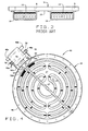
- a stove or range 1 has a glass/ceramic cooking top 3.
- the cook top has a number of defined areas 5 on which cooking utensils are placed for heating food.
- a control panel 7 conveniently placed for the user of the stove has separate control knobs 9 or the like for separately controlling the temperature to which each area 5 is heated.
- the areas are heated by coils 11 of electrical resistance wire.
- the coils are mounted in pans 13 that are located on the underside of the cooking top. When a current is supplied to the wire, the resulting heat which is generated is radiated onto the underside of top 3 to elevate the surface temperature of the defined areas.
- the pans typically include a liner 17 of an insulation material and the coils 11 are placed on this liner. As shown in Fig. 3, the coils are arranged in a particular pattern to increase the efficiency of the heating.
- a control unit 19 is attached to a sidewall 21 of the pan.
- the control unit has electrical terminals 23a, 23b which are electronically connected to one of the temperature control knobs 9.
- the control unit has additional terminals 25a, 25b for connecting the control unit to respective ends of the heating wire.
- a temperature sensor rod 27 extends diagonally across the pan above the wire. The rod is connected to a switch within the control unit. If the temperature sensed by the rod exceeds a predetermined temperature, the switch acts to open the circuit path to the wire interrupting current flow through the wire.
- a multi-pin terminal block 29 is mounted to the sidewall 27 of pan 13 to one side of the location of the control unit.
- a retainer 31 is used to hold the block in place.
- block 29 is shown to accommodate four terminals 33.
- a bus bar 35 is used to short three of the terminals together.
- One end of wire 11 is attached to one of the terminals 33, and the other end of the wire is attached to one of the three commonly connected terminals.
- a pair of jumper wires 37 having appropriate connectors at each end are used to bridge the terminals 25a, 25b of the control unit which the appropriate terminals 33 on block 29, to complete the electrical circuit between the control unit and heating wire.
- Apparatus 40 of the present invention comprises an improved heating unit as shown in Fig. 4.
- Unit 40 includes a pan 42 which is similar to pan 13 and is also positioned adjacent an area 5 of the cook top 3 to be heated.
- a liner 17 of an insulation material is installed in the pan; and, a coiled wire, resistance type heating element 11 is placed on top of the liner in the same manner previously described.
- heat generated by passing a current through the wire is radiated at the surface to be heated.
- a control unit 44 is mounted to a side 46 of the pan.
- the control unit includes a first set of terminals 46a, 46b by which the heater assembly is electrically connected to knob 9; and a second set of terminals 48a, 48b for connecting the ends of wire 11 to the control unit.
- the control unit has a sensor rod 27 and an internal cut-off switch for disrupting current flow to the heating element if an over-temperature condition occurs.
- Heating unit 42 includes a sleeve means 52 fitting over the respective ends 50a, 50b of wire 11 to provide a thermal insulation between the resistance wire and the control unit.
- the ends 50a, 50b are made long enough to extend from the coiled portion of the wire to openings 54 in the sidewall of the pan and from the side of the pan to the terminals.
- Sleeve means 52 includes ceramic sleeves 52a, 52b fitting over the lengths of wire extending between the sidewall of the pan and the respective terminals 48a, 48b.
- the sleeves provide a thermal insulation which reduces the heat loss of the wire to increase the efficiency of the heating unit.
- the outer end of the wires extend beyond the outer end of the respective sleeves and rest upon their associated control unit terminal.
- the ends of the heater wire can be directly welded to the terminals by ultrasonic welding.
- a tab means 56 includes tabs which can be placed over the end of the wire resting upon a terminal. The tabs 56 are weld tabs and are used to facilitate resistance welding of the wire ends to their respective terminals.
- the heating unit for use with stoves or ranges with a glasstop cooking surface.
- the heating unit is readily mounted beneath a cooking top to heat a defined area to a desired cooking temperature.
- the unit requires substantially fewer components than prior heating unit constructions; and, fewer steps are required to assemble the unit. These factors significantly reduce the manufacturing cost of the unit. During operation, heat losses are reduced thereby making the unit more efficient than prior heating units.
- the heating unit includes a resistor wire, coil wound heating element which is simply and easily attached to a control unit for the heating unit.
- the heating unit when installed beneath the cook top, operates in the same manner as prior heating units.
- the heating unit is easily replaced so to reduce repair and replacement costs; and, the heating unit can be used either as original equipment on new stoves, or as a replacement part on existing stoves.
Landscapes
- Chemical & Material Sciences (AREA)
- Engineering & Computer Science (AREA)
- Ceramic Engineering (AREA)
- Electric Stoves And Ranges (AREA)
- Resistance Heating (AREA)
Applications Claiming Priority (2)
| Application Number | Priority Date | Filing Date | Title |
|---|---|---|---|
| US65660696A | 1996-05-31 | 1996-05-31 | |
| US656606 | 1996-05-31 |
Publications (1)
| Publication Number | Publication Date |
|---|---|
| EP0810814A2 true EP0810814A2 (fr) | 1997-12-03 |
Family
ID=24633775
Family Applications (1)
| Application Number | Title | Priority Date | Filing Date |
|---|---|---|---|
| EP19970630030 Withdrawn EP0810814A2 (fr) | 1996-05-31 | 1997-05-30 | Raccordement pour filament de chauffage par radiation |
Country Status (2)
| Country | Link |
|---|---|
| EP (1) | EP0810814A2 (fr) |
| CA (1) | CA2207554A1 (fr) |
Cited By (4)
| Publication number | Priority date | Publication date | Assignee | Title |
|---|---|---|---|---|
| WO2003081952A1 (fr) * | 2002-03-22 | 2003-10-02 | Ceramaspeed Limited | Ensemble chauffant electrique |
| WO2004016046A1 (fr) * | 2002-08-13 | 2004-02-19 | Ceramaspeed Limited | Chauffage electrique par rayonnement comprenant un dispositif de limitation de temperature |
| WO2004028209A1 (fr) * | 2002-09-17 | 2004-04-01 | Ceramaspeed Limited | Corps de chauffe electrique et procede de fabrication |
| WO2004066678A1 (fr) * | 2003-01-18 | 2004-08-05 | Ceramaspeed Limited | Dispositif thermosensible |
-
1997
- 1997-05-28 CA CA 2207554 patent/CA2207554A1/fr not_active Abandoned
- 1997-05-30 EP EP19970630030 patent/EP0810814A2/fr not_active Withdrawn
Cited By (10)
| Publication number | Priority date | Publication date | Assignee | Title |
|---|---|---|---|---|
| WO2003081952A1 (fr) * | 2002-03-22 | 2003-10-02 | Ceramaspeed Limited | Ensemble chauffant electrique |
| US7030342B2 (en) | 2002-03-22 | 2006-04-18 | Ceramaspeed Limited | Electrical heating assembly |
| WO2004016046A1 (fr) * | 2002-08-13 | 2004-02-19 | Ceramaspeed Limited | Chauffage electrique par rayonnement comprenant un dispositif de limitation de temperature |
| GB2407014A (en) * | 2002-08-13 | 2005-04-13 | Ceramaspeed Ltd | Radiant electric heater incorporating a temperature-limiting device |
| GB2407014B (en) * | 2002-08-13 | 2005-08-24 | Ceramaspeed Ltd | Radiant electric heater incorporating a temperature-limiting device |
| WO2004028209A1 (fr) * | 2002-09-17 | 2004-04-01 | Ceramaspeed Limited | Corps de chauffe electrique et procede de fabrication |
| GB2409139A (en) * | 2002-09-17 | 2005-06-15 | Ceramaspeed Ltd | Electric heater and method of manufacture |
| GB2409139B (en) * | 2002-09-17 | 2005-11-09 | Ceramaspeed Ltd | Method of manufacturing an Electric Heater |
| WO2004066678A1 (fr) * | 2003-01-18 | 2004-08-05 | Ceramaspeed Limited | Dispositif thermosensible |
| US7193192B2 (en) | 2003-01-18 | 2007-03-20 | Ceramaspeed Limited | Temperature-responsive device |
Also Published As
| Publication number | Publication date |
|---|---|
| CA2207554A1 (fr) | 1997-11-30 |
Similar Documents
| Publication | Publication Date | Title |
|---|---|---|
| US6555793B2 (en) | Advanced radiant electric heater | |
| US4538051A (en) | Heating element for heating boiling plates, hotplates and the like | |
| CA1266293A (fr) | Appareils chauffant aux infrarouges | |
| EP0037638B1 (fr) | Appareil de cuisson | |
| JPH03176987A (ja) | 輻射電気ヒータ | |
| EP0560708B1 (fr) | Appareil de chauffage et sonde pour une plaque de cuisson | |
| EP1400151B1 (fr) | Appareil de cuisson | |
| US4650969A (en) | Electric hotplate | |
| EP0810814A2 (fr) | Raccordement pour filament de chauffage par radiation | |
| GB2275161A (en) | A radiant electric heating element | |
| CN1264276A (zh) | 电热元件 | |
| EP1791397B1 (fr) | Procédé de fabrication d'un dispositif de chauffage électrique par rayonnement | |
| EP0437326B1 (fr) | Systèmes de contrÔle de température et méthode d'exploitation | |
| US5968391A (en) | Modular radiant heating unit | |
| EP1466502B1 (fr) | Appareil et procede de commande d'un ensemble chauffage electrique | |
| GB2136659A (en) | An electric heating element particularly for hot-plates | |
| US20210080115A1 (en) | Coil heating element with a heat transfer disk | |
| EP0774881B1 (fr) | Dispositif de chauffage à infra-rouge | |
| US6172343B1 (en) | Heater and heater control with selective power rating | |
| EP0954202B1 (fr) | Elément de chauffage électrique rayonnant | |
| US6300604B1 (en) | Radiant electric heater | |
| EP0892584A2 (fr) | Dispositif chauffant destiné à des cuisinières | |
| CA2205257C (fr) | Cartouche a cuisson par induction utilisables avec des interrupteurs bimetalliques | |
| CA1278011C (fr) | Element chauffant embrochable a surface unie | |
| US7193192B2 (en) | Temperature-responsive device |
Legal Events
| Date | Code | Title | Description |
|---|---|---|---|
| PUAI | Public reference made under article 153(3) epc to a published international application that has entered the european phase |
Free format text: ORIGINAL CODE: 0009012 |
|
| AK | Designated contracting states |
Kind code of ref document: A2 Designated state(s): DE ES GB IT |
|
| STAA | Information on the status of an ep patent application or granted ep patent |
Free format text: STATUS: THE APPLICATION HAS BEEN WITHDRAWN |
|
| 18W | Application withdrawn |
Withdrawal date: 19980716 |