EP1466502B1 - Appareil et procede de commande d'un ensemble chauffage electrique - Google Patents
Appareil et procede de commande d'un ensemble chauffage electrique Download PDFInfo
- Publication number
- EP1466502B1 EP1466502B1 EP03701576A EP03701576A EP1466502B1 EP 1466502 B1 EP1466502 B1 EP 1466502B1 EP 03701576 A EP03701576 A EP 03701576A EP 03701576 A EP03701576 A EP 03701576A EP 1466502 B1 EP1466502 B1 EP 1466502B1
- Authority
- EP
- European Patent Office
- Prior art keywords
- temperature
- heater
- level
- heating zone
- temperature level
- Prior art date
- Legal status (The legal status is an assumption and is not a legal conclusion. Google has not performed a legal analysis and makes no representation as to the accuracy of the status listed.)
- Expired - Lifetime
Links
Images




Classifications
-
- H—ELECTRICITY
- H05—ELECTRIC TECHNIQUES NOT OTHERWISE PROVIDED FOR
- H05B—ELECTRIC HEATING; ELECTRIC LIGHT SOURCES NOT OTHERWISE PROVIDED FOR; CIRCUIT ARRANGEMENTS FOR ELECTRIC LIGHT SOURCES, IN GENERAL
- H05B3/00—Ohmic-resistance heating
- H05B3/68—Heating arrangements specially adapted for cooking plates or analogous hot-plates
- H05B3/74—Non-metallic plates, e.g. vitroceramic, ceramic or glassceramic hobs, also including power or control circuits
- H05B3/746—Protection, e.g. overheat cutoff, hot plate indicator
-
- H—ELECTRICITY
- H05—ELECTRIC TECHNIQUES NOT OTHERWISE PROVIDED FOR
- H05B—ELECTRIC HEATING; ELECTRIC LIGHT SOURCES NOT OTHERWISE PROVIDED FOR; CIRCUIT ARRANGEMENTS FOR ELECTRIC LIGHT SOURCES, IN GENERAL
- H05B2213/00—Aspects relating both to resistive heating and to induction heating, covered by H05B3/00 and H05B6/00
- H05B2213/07—Heating plates with temperature control means
Definitions
- This invention relates to a method of avoiding unacceptably high temperatures of a wall adjacent to a cooking appliance.
- a radiant electric heater When a radiant electric heater is operating beneath a glass-ceramic cooking plate, in order to heat a cooking vessel located on an upper surface of the cooking plate, the lower surface of the cooking plate is heated by direct radiation from the heater and heat is transferred through the cooking plate to the cooking vessel on the upper surface.
- the radiant heaters in a glass-ceramic cooktop appliance will transmit heat to a back wall, for example a wall of a kitchen, and to any side wall adjacent to the cooktop. Temperature limits for the back wall and any side walls are specified in European Safety Standard EN60335.
- temperature limiters are provided in heaters to de-energise the heaters at a predetermined temperature.
- Such limiters which have generally been of electro-mechanical construction, are set to respond to the temperature of the upper surface of the cooking plate.
- the temperature limiter is generally set to switch, in free radiation conditions, at a relatively low temperature of the upper surface (commonly referred to as top glass temperature), which may be less than 550 degrees Celsius.
- top glass temperature a relatively low temperature of the upper surface
- Such an arrangement is unsatisfactory as it means that the rate of heat transfer, particularly to cooking vessels having less than ideal contact with the upper surface of the cooking plate, is reduced by premature switching of the limiter, making it impossible to make maximum and optimum use of the available power of the heaters.
- EP-A-0 886 459 It is known from EP-A-0 886 459 to provide an initial temperature boost such that the temperature of a glass ceramic cooking plate exceeds a predetermined continuous safe level. This is balanced by subsequently reducing the temperature such that in the longer term the continuous safe temperature is not exceeded.
- the initial boost is relatively short, about 10 minutes, and the subsequent temperature reduction is to preserve the life of the glass ceramic cooktop, not to satisfy back wall and side wall temperature requirements.
- a method of avoiding unacceptably high temperatures of a wall adjacent to a cooking appliance comprising:
- the heater may be energised at a boost power level, in excess of the first power level.
- the second temperature level may be between about 75 percent and about 85 percent, preferably about 83 percent, of the first temperature level.
- the length of the predetermined initial period may be dependent on the time elapsed since the control means was last at full power.
- the length of the predetermined initial period may be inversely proportional to the time elapsed since the control means was last at the full power level.
- Reduction from the first temperature level to the second temperature level may be effected in a continuous or stepwise manner. If stepwise it may be effected in a single step or in a plurality of steps.
- the control means may comprise a microprocessor-based controller into which the predetermined initial period and a setting for the second temperature level are permanently programmed for automatic implementation.
- the temperature sensor may provide an electrical output as a function of temperature of the upper surface of the glass-ceramic cooking plate.
- the temperature sensor may comprise a device whose electrical resistance changes as a function of temperature and may comprise a platinum resistance temperature detector.
- the temperature sensor may be provided on, or spaced behind, the lower surface of the glass-ceramic cooking plate.
- the heater may have a main heating zone at least partially surrounded by at least one additional heating zone, the main heating zone being energisable alone or together with the at least one additional heating zone.
- the at least one additional heating zone may be arranged against at least one side of the main heating zone, for example at opposite sides thereof.
- the predetermined initial time may be about 20 minutes to about 40 minutes when the main heating zone is energised together with the at least one additional heating zone, and may be about 30 minutes to about 50 minutes when the main heating zone is energised alone.
- the predetermined initial time may be about 20 minutes to about 40 minutes.
- the present invention enables full available power of a radiant heater to be applied for the maximum period of time, without the specified limit temperature for EN60335 being exceeded.
- the settings for the predetermined initial period and the second temperature level are determined by experiment during manufacture, for each specific heater assembly, and fixedly programmed into the control means during the manufacturing process.
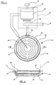
- an electric heater 10 is arranged beneath a glass-ceramic cooking plate 12 in the cooking appliance 2.
- the heater 10 comprises a metal dish 14 having a base layer 16 of thermal insulation material, such as microporous thermal insulation material.
- a heating element 18 is supported on the base layer 16.
- the heating element 18 comprises a corrugated metal ribbon supported edgewise on the base layer 16.
- the heating element 18 could comprise other forms, such as wire or foil, or one or more infrared lamps. Any of the well-known forms of heating element, or combinations thereof, could be considered.
- a peripheral wall 20 of thermal insulation material is provided, a top surface of which contacts a lower surface 22 of the glass-ceramic cooking plate 12.
- a temperature sensor 24 is arranged to extend partially across the heater, between the heating element 18 and the cooking plate 12.
- the temperature sensor 24 comprises a tube containing a device which provides an electrical output as a function of temperature or a beam or other member carrying a device which provides an electrical output as a function of temperature.
- Such device may have an electrical parameter, such as electrical resistance, which changes as a function of temperature.
- the device comprises a platinum resistance temperature detector.
- a temperature sensor could be provided deposited on, or secured in contact with, the lower surface 22 of the cooking plate 12.
- a terminal block 26 is arranged at the edge of the heater and by means of which the heating element 18 is electrically connected to a power supply 28 for energising.
- Control circuitry 30 is provided for the heater 10.
- Such control circuitry comprises a microcontroller 32, which is a microprocessor-based control unit.
- An energy regulator 34 is also provided, which has a control knob 36 by means of which a plurality of user-selectable energy (power level) settings of the heater 10, including a full power setting, can be achieved in known manner.
- Power is supplied to the heater 10 from the power supply 28 by way of a relay 38, or by way of a solid state switch means, such as a triac.
- the temperature sensor 24 is calibrated in association with the microcontroller 32 to provide an electrical output which is tuned as a function of temperature of an upper surface 40 of the cooking plate 12, which upper surface 40 is arranged to receive a cooking vessel 42.
- the temperature of the glass-ceramic cooking plate 12 must not exceed a certain level in order to prevent thermal damage to the glass-ceramic material. For optimum cooking performance, it is required to be able to heat up the cooking vessel 42 and its contents as rapidly as possible, for example to achieve rapid boiling of the contents of the cooking vessel 42. Accordingly, it is desirable for the temperature of the upper surface 40 of the cooking plate 12, at which the temperature sensor 24 operates for controlling the heater 18, to be as high as permissible. However, this must not be such as to result in an unacceptably high temperature of the cooking plate 12, or an unacceptably high temperature of the back wall a limit for which is specified in European Safety Standard EN60335.
- the power level of the heater 10 is then reduced such that the temperature of the cooking plate is reduced from the first temperature level to a second temperature level which is between about 75 percent and 85 percent, preferably about 83 percent, of the first temperature level (corresponding to a power level of about 60 percent to about 70 percent of the power level corresponding to the first temperature level), the temperature of the back wall 6 and side wall 8 is maintained at a level which does not exceed the specified limit.
- the microcontroller 32 is programmed in the factory, during manufacture of the heater 10 and its associated control circuitry, with the necessary data for the predetermined initial period and the reduced temperature level. Such programmed data is thereafter automatically implemented by the microcontroller 32 to control the heater 10.
- FIG 4 is a plot of the temperature TE in degrees Celsius of the upper surface 40 of the cooking plate 12 (known as the top glass temperature) against time TI in minutes at the full power setting.
- the heater 10 is operated at a boost power level for a period B of about 7 minutes, followed by operation at a normal full power level for a further 23 minutes.
- the temperature of the upper surface 40 of the cooking plate 12 exceeds 600 degrees Celsius and during the remainder of the predetermined initial period the temperature of the upper surface 40 of the cooking plate 12 is maintained at around 600 degrees Celsius. This enables rapid heating to boiling to take place in the cooking vessel 42.
- the microcontroller 32 automatically reduces the power level of the heater 10 to a lower fallback level such that the temperature of the cooking plate reduces to a second temperature which is about 75 to 85 percent, preferably about 83 percent, of the previous (first) temperature level.
- Such reduction can be effected in one or more steps, or continuously.
- the temperature of the upper surface 40 of the cooking plate 12 is maintained at about 500 degrees Celsius and this ensures that the back wall 6 and side wall 8 are maintained at a temperature which does not exceed the specified limit.
- the reduced temperature level is not such as to interfere with a temperature band 46, required for frying activities, and a temperature band 48, required for continuous boiling/simmering activities.
- the heater 10 may be switched off, or to a lower power level setting, by a user and then back to full power while the temperature of the back wall 6 and side wall 8 is still elevated.
- the fallback (second) temperature level requires to be re-introduced in a short time compared with the situation when the heater is first energised.
- the time at full (first) power i.e., first temperature
- first temperature originally set to full power
- the time before the heater is operated at the fallback temperature level may be the initial time (e.g., 30 minutes) less half the time interval since the heater was last at full power.
- the heater is switched to full power, and reverts to the fallback temperature level after 30 minutes as shown by point E.
- the heater is then switched off, or to low power, at 40 minutes as represented by point F and is subsequently switched back to full power at 50 minutes as represented by point G.
- the heater remains at full power for (50 - 30)/2 minutes, i.e. 10 minutes, before reverting to the fallback temperature level as represented by point H.
- the power level is set by the control circuitry at the boost power level for a period of 7 minutes to provide accelerated initial heat up.
- the power level is reduced to normal full power, that is to the first temperature.
- the temperature level reverts to the fallback (second) temperature level.
- the heat output is such that the temperature of the back wall 6 and the side wall 8 will not exceed the maximum specified by EN60335, but at the same time is sufficient to maintain a significant volume of water at a fast boil or to fry.
- the user switches the heater off or to a lower power setting.
- the user switches the heater back to full power.
- the control circuitry maintains the full power (first temperature) level for half of twenty minutes, i.e. for 10 minutes, and at point H, after 10 minutes at full power, the temperature level reverts to the fallback (second) temperature level.
- the manner in which the time before the heater reverts to fallback temperature level is determined may be established from experimental data and could be other than a simple inverse proportionality.
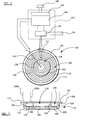
- an electric heater 110 is arranged beneath a glass-ceramic cooking plate 112 in a cooking appliance (not shown in detail).
- the heater 110 comprises a metal dish 114 having a base layer 116 of thermal insulation material, such as microporous thermal insulation material.
- the heater 110 is arranged to provide two concentric heating zones.
- a main heating zone 118 is surrounded by an additional heating zone 120, the zones 118, 120 being separated by a dividing wall 122 of thermal insulation material, a top surface of which contacts a lower surface 124 of the glass-ceramic cooking plate 112.
- a peripheral wall 126 of thermal insulation material is also provided, having a top surface which contacts the lower surface 124 of the glass-ceramic cooking plate 112.
- the centrally located main heating zone 118 has at least one heating element 128, supported relative to the base layer 116.
- the additional heating zone 120 also has at least one heating element 130, supported relative to the base layer 116.
- the heating elements 128, 130 are of well known form and may, for example, comprise corrugated metal ribbon elements.
- a terminal block 132 is arranged at the edge of the heater 110 and by means of which the heating elements 128, 130 are electrically connected to a power supply 134 for energising.
- the heating elements 128, 130 are arranged to be connected so that the heating element 128 can be operated alone, whereby the main heating zone 118 is energised alone, for heating a small cooking vessel 136A located on an upper surface 138 of the cooking plate 112.
- the heating element 128 can also be operated together with the heating element 130, whereby the main heating zone 118 is energised together with the additional heating zone 120, for heating a larger cooking vessel 136B located on the upper surface 138 of the cooking plate 112.
- a temperature sensor 140 is arranged to extend partially across the heater, between the heating elements 128, 130 and the cooking plate 112.
- the temperature sensor 140 comprises a tube containing a device which provides an electrical output as a function of temperature.
- Such device may have an electrical parameter, such as electrical resistance, which changes as a function of temperature.
- the device comprises a platinum resistance temperature detector.
- a temperature sensor could be provided deposited on, or secured in contact with, the lower surface 124 of the cooking plate 112.
- Control circuitry 142 is provided for the heater 110.
- Such control circuitry comprises a microcontroller 144, which is a microprocessor-based control unit.
- An energy regulator 146 is also provided, which has a control knob 148 by means of which a plurality of user-selectable energy (power level) settings of the heater 110, including a full power setting, can be achieved in known manner.
- Power is supplied to the heater 110 from the power supply 134 by way of a relay 150, or by way of a solid state switch means, such as a triac.
- the temperature sensor 140 is calibrated in association with the microcontroller 144 to provide an electrical output which is tuned as a function of temperature of the upper surface 138 of the cooking plate 112.
- the temperature of the glass-ceramic cooking plate 112 must not exceed a certain level in order to prevent thermal damage to the glass-ceramic material. For optimum cooking performance, it is required to be able to heat up the cooking vessel 136A, 136B and its contents as rapidly as possible, for example to achieve rapid boiling of the contents of the cooking vessel 136A, 136B. Accordingly, it is desirable for the temperature of the upper surface 138 of the cooking plate 112, at which the temperature sensor 140 operates for controlling the heater 110, to be as high as permissible. However, as noted previously this must not be such as to result in an unacceptably high temperature of the cooking plate 112, or an unacceptably high temperature of the back wall 6 or side wall 8, a limit for which is specified in European Safety Standard EN60335.
- the temperature level of the heater 110 is then reduced from the first temperature level to a second temperature level which is between about 75 percent and about 85 percent, preferably about 83 percent, of the first temperature level, the temperature of the back wall 6 and side wall 8 is maintained at a level which does not exceed the specified limit.
- the heater 110 is operated in a free radiation condition at a full temperature (power) level setting with the main heating zone 118 energised together with the additional heating zone 120, then because of the higher resulting power and the larger heated area, the temperature of the back wall 6 and side wall 8 rises more rapidly and their specified temperature limit is reached sooner than when the main heating zone is energised alone.
- the predetermined initial period which can be safely maintained at the first temperature level, before reducing to the second temperature level, without the temperature of the back wall 6 and side wall 8 exceeding the specified limit is shorter and is from about 20 to about 40 minutes and is typically about 30 minutes. However, under certain circumstances the predetermined initial period can be as little as 10 minutes.
- the microcontroller 144 is programmed in the factory, during manufacture of the heater 110 and its associated control circuitry, with the necessary data for the values of the predetermined initial period, according to whether the main heating zone 118 is energised alone or together with the additional heating zone 120, and also the value for the reduced second temperature level. Such programmed data is thereafter automatically implemented by the microcontroller 144 to safely control the heater 110.
- FIG 8 is a plot of the temperature TE in degrees Celsius of the upper surface 138 of the cooking plate 112 (known as the top glass temperature) against time TI in minutes at the full power setting.
- the heater 110 is operated at a boost power level for a period B of about 7 minutes, followed by operation at a normal first temperature (full power) level for a further 33 minutes.
- the boost period the temperature of the upper surface 138 of the cooking plate 112 exceeds 600 degrees Celsius and during the remainder of the predetermined initial period A1 the temperature of the upper surface 138 of the cooking plate 112 is maintained at around 600 degrees Celsius.
- the microcontroller 144 automatically reduces the temperature level of the heater 110 to a lower (second) fallback temperature level which is about 75 to 85 percent of the previous full (first) temperature level. Such reduction, as denoted by reference numeral 152, can be effected in one or more steps, or continuously.
- the temperature of the upper surface 138 of the cooking plate 112 is maintained at about 500 degrees Celsius and this ensures that the back wall 6 and side wall 8 are maintained at a temperature which does not exceed the specified limit.
- the reduced temperature level is not such as to interfere with a temperature band 154, required for frying activities, and a temperature band 156, required for continuous boiling/simmering activities.
- the temperature of the back wall 6 and side wall 8 rises more rapidly and reaches its specified limit sooner than when the main heating zone 118 is energised alone at the boost power level followed by the normal full (first) temperature level.
- a reduced predetermined initial period A2 of about 30 minutes is automatically implemented by the microcontroller 144 and at the end of which the temperature level is automatically reduced by the microcontroller 144 to the lower (second temperature) fallback level, as denoted by reference numeral 152A and shown by the broken line portion of the graph. This ensures that the specified limit for the temperature of the back wall 6 and side wall 8 is not exceeded, while ensuring optimised performance of the heater 110.
- the heater 110 may be switched off, or to a lower power level setting, by a user and then back to full power while the temperature of the back wall 6 and side wall 8 is still elevated.
- the fallback (second) temperature level requires to be re-introduced in a short time compared with the situation when the heater is first energised.
- the time at full (first) temperature, originally set to full power may be reduced by an amount inversely proportional to the time interval since the heater was last at full power.
- Figure 6 shows a heater 110 in which the main heating zone 118 is concentrically arranged with the additional heating zone 120
- a heater 110 may comprise an oval arrangement in which the main heating zone 118, provided with heating element 128, is bordered at one side by the additional heating zone 120, provided with heating element 130.
- the heater 110 has a peripheral wall 126 of thermal insulation material and a dividing wall 122, also of thermal insulation material.
- a heater 110 may comprise what is known as an angel arrangement in which the main heating zone 118, provided with heating element 128, is bordered on opposite sides by wing-like additional heating zones 120, provided with heating elements 130.
- the heater 110 has a dividing wall arrangement 122 of thermal insulation material and a peripheral wall arrangement 126, also of thermal insulation material.
- the heaters 110 of Figures 9 and 10 are operated and controlled in the same way as the heater 110 of Figure 6.
Landscapes
- Chemical & Material Sciences (AREA)
- Engineering & Computer Science (AREA)
- Ceramic Engineering (AREA)
- Electric Stoves And Ranges (AREA)
- Control Of Resistance Heating (AREA)
- Operation Control Of Excavators (AREA)
- Remote Monitoring And Control Of Power-Distribution Networks (AREA)
- Selective Calling Equipment (AREA)
- Electrical Discharge Machining, Electrochemical Machining, And Combined Machining (AREA)
Claims (21)
- Procédé prévu pour éviter des températures excessivement élevées d'un mur contigu à un appareil de cuisson comportant :caractérisé en ce queune plaque en vitrocéramique (12, 112) ayant une surface supérieure prévue pour recevoir un récipient de cuisson (42, 136A, 136B) et une surface inférieure;un dispositif de chauffage électrique à rayonnement (10, 110) disposé à la surface inférieure d'une plaque de cuisson en vitrocéramique (12, 112) ; etun dispositif de commande électronique comprenant :une sonde de température (24, 140) pour surveiller la température au niveau ou à proximité de la plaque de cuisson, ladite sonde fournissant un signal électrique fonction de la température ; etun moyen de commande (30, 142) connecté à la sonde de température et au dispositif de chauffage, pour commander la mise sous tension du dispositif de chauffage à partir d'une alimentation électrique (28, 134), le moyen de commande étant adapté et agencé pour mettre le dispositif de chauffage sous tension à une pluralité de niveaux de puissance sélectionnables par l'utilisateur, comprenant un niveau de puissance maximum,
le moyen de commande (30, 142) est adapté de telle sorte que, lorsque le dispositif de chauffage (10, 110) est mis sous tension au niveau de puissance maximum, afin d'éviter des températures excessivement élevées d'un mur contigu à l'appareil de cuisson, le dispositif de chauffage est mis sous tension pour chauffer la plaque de cuisson (12, 112) à un premier niveau de température pendant une période initiale prédéterminée de 20 à 50 minutes et est ensuite mis sous tension pour chauffer la plaque de cuisson à un second niveau de température plus bas que le premier niveau de température. - Procédé selon la revendication 1, caractérisé en ce que, pendant une faible proportion initiale de la période initiale prédéterminée, le dispositif de chauffage (10, 110) est mis sous tension à un niveau de température accru, supérieur au premier niveau de température.
- Procédé selon la revendication 1 ou 2, caractérisé en ce que le second niveau de température est compris entre environ 75% et environ 85% du premier niveau de température.
- Procédé selon la revendication 3, caractérisé en ce que la seconde température est d'environ 83% du premier niveau de température.
- Procédé selon l'une quelconque des revendications précédentes, caractérisé en ce que la longueur de la période initiale prédéterminée dépend du temps écoulé depuis la dernière utilisation du moyen de commande (30, 142) au niveau de puissance maximum.
- Procédé selon la revendication 5, caractérisé en ce que la longueur de la période initiale prédéterminée est inversement proportionnelle au temps écoulé depuis la dernière utilisation du moyen de commande (30, 142) au niveau de puissance maximum.
- Procédé selon l'une quelconque des revendications précédentes, caractérisé en ce que la réduction du premier niveau de température au second niveau de température est assurée de manière continue.
- Procédé selon l'une quelconque des revendications 1 à 6, caractérisé en ce que la réduction du premier niveau de température au second niveau de température est assurée par étapes.
- Procédé selon la revendication 8, caractérisé en ce que la réduction du premier niveau de température au second niveau de température est assurée en une seule étape.
- Procédé selon la revendication 9, caractérisé en ce que la réduction du premier niveau de température au second niveau de température est assurée en une pluralité d'étapes.
- Procédé selon l'une quelconque des revendications précédentes, caractérisé en ce que le moyen de commande (30, 142) comporte une unité de commande à microprocesseur (32, 144) dans laquelle la période initiale prédéterminée et un réglage pour le second niveau de température sont programmés pour une mise en oeuvre automatique.
- Procédé selon l'une quelconque des revendications précédentes, caractérisé en ce que la sonde de température (24, 140) fournit un signal électrique fonction de la température de la surface supérieure de la plaque de cuisson en vitrocéramique (12, 112).
- Procédé selon l'une quelconque des revendications précédentes, caractérisé en ce que la sonde de température (24, 140) comporte un dispositif dont la résistance électrique change en fonction de la température.
- Procédé selon la revendication 13, caractérisé en ce que la sonde de température (24, 140) comprend un détecteur de température à résistance en platine.
- Procédé selon l'une quelconque des revendications précédentes, caractérisé en ce que la sonde de température (24, 140) est prévue sur, ou espacée derrière la surface inférieure de la plaque de cuisson en vitrocéramique (12, 112).
- Procédé selon l'une quelconque des revendications précédentes, caractérisé en ce que le dispositif de chauffage (110) a une zone chauffante principale (118) entourée au moins partiellement d'au moins une zone chauffante supplémentaire (120), la zone chauffante principale pouvant être mise sous tension seule ou conjointement avec au moins une zone chauffante supplémentaire.
- Procédé selon la revendication 16, caractérisée en ce que la ou les zones chauffantes supplémentaires (120) sont agencée essentiellement concentriquement avec la zone chauffante principale (118).
- Procédé selon la revendication 17, caractérisé en ce que la ou les zones chauffantes supplémentaires (120) sont agencées contre au moins un côté de la zone chauffante principale (118).
- Procédé selon la revendication 18, caractérisé en ce que la ou les zones chauffantes supplémentaires (120) sont agencées sur des côtés opposés de la zone chauffante principale (118).
- Procédé selon l'une quelconque des revendications 16 à 19, caractérisé en ce que le temps initial prédéterminé est d'environ 20 minutes à environ 40 minutes lorsque la zone chauffante principale (118) est sous tension en même temps que la ou les zones chauffantes supplémentaires (120), et d'environ 30 minutes à environ 50 minutes lorsque la zone chauffante principale (118) est seule sous tension.
- Procédé selon l'une quelconque des revendications précédentes, caractérisé en ce que le temps initial prédéterminé est d'environ 20 minutes à environ 40 minutes.
Applications Claiming Priority (3)
| Application Number | Priority Date | Filing Date | Title |
|---|---|---|---|
| GB0200914 | 2002-01-16 | ||
| GBGB0200914.0A GB0200914D0 (en) | 2002-01-16 | 2002-01-16 | Apparatus and method for controlling an electric assembly |
| PCT/GB2003/000172 WO2003063551A1 (fr) | 2002-01-16 | 2003-01-16 | Appareil et procede de commande d'un ensemble chauffage electrique |
Publications (2)
| Publication Number | Publication Date |
|---|---|
| EP1466502A1 EP1466502A1 (fr) | 2004-10-13 |
| EP1466502B1 true EP1466502B1 (fr) | 2005-07-27 |
Family
ID=9929161
Family Applications (1)
| Application Number | Title | Priority Date | Filing Date |
|---|---|---|---|
| EP03701576A Expired - Lifetime EP1466502B1 (fr) | 2002-01-16 | 2003-01-16 | Appareil et procede de commande d'un ensemble chauffage electrique |
Country Status (7)
| Country | Link |
|---|---|
| US (1) | US7342205B2 (fr) |
| EP (1) | EP1466502B1 (fr) |
| AT (1) | ATE300856T1 (fr) |
| DE (1) | DE60301123T2 (fr) |
| ES (1) | ES2247511T3 (fr) |
| GB (1) | GB0200914D0 (fr) |
| WO (1) | WO2003063551A1 (fr) |
Families Citing this family (9)
| Publication number | Priority date | Publication date | Assignee | Title |
|---|---|---|---|---|
| GB0322170D0 (en) * | 2003-09-23 | 2003-10-22 | Ceramaspeed Ltd | Apparatus for control of boiling level |
| DE102004050125A1 (de) * | 2004-10-14 | 2006-04-20 | BSH Bosch und Siemens Hausgeräte GmbH | Gargeräteheizvorrichtung |
| DE102006038832A1 (de) | 2006-03-23 | 2007-09-27 | Electrovac Ag | Verfahren sowie Schaltungsanordnung zum Steuern wenigstens eines Heizelementes eines Heizgerätes |
| EP1937032B1 (fr) * | 2006-12-20 | 2020-11-04 | Electrolux Home Products Corporation N.V. | Appareil ménager |
| TW201421181A (zh) | 2012-09-14 | 2014-06-01 | Kaz Europe Sa | 具有節能操作之加熱器及相關方法 |
| US20150060435A1 (en) * | 2013-08-30 | 2015-03-05 | General Electric Company | Cooktop appliance and a method for operating the same |
| US10584882B2 (en) * | 2017-02-27 | 2020-03-10 | Haier Us Appliance Solutions, Inc. | Electric cooktop appliance with heat control |
| WO2020112981A1 (fr) | 2018-11-29 | 2020-06-04 | Broan-Nutone Llc | Système intelligent de ventilation d'air intérieur |
| US11570853B2 (en) * | 2021-02-01 | 2023-01-31 | E.G.O. Elektro-Geraetebau Gmbh | Method for actuating a heating device of a hob, and hob |
Family Cites Families (6)
| Publication number | Priority date | Publication date | Assignee | Title |
|---|---|---|---|---|
| JPS55151779A (en) * | 1979-05-15 | 1980-11-26 | Matsushita Electric Industrial Co Ltd | Heater with program timer |
| DE3007037A1 (de) * | 1980-02-26 | 1981-09-03 | Ego Elektro Blanc & Fischer | Glaskeramik-kochgeraet |
| US5293028A (en) * | 1987-01-05 | 1994-03-08 | General Electric Company | Cooktop appliance with improved power control |
| GB2325533B (en) | 1997-05-22 | 2001-08-08 | Ceramaspeed Ltd | Method and apparatus for controlling an electric heater |
| GB2333406B (en) * | 1998-01-16 | 2001-10-10 | Ceramaspeed Ltd | Radiant electric heater |
| DE29923976U1 (de) | 1999-12-15 | 2001-08-23 | BSH Bosch und Siemens Hausgeräte GmbH, 81669 München | Kochfeld mit Sensoreinheit |
-
2002
- 2002-01-16 GB GBGB0200914.0A patent/GB0200914D0/en not_active Ceased
-
2003
- 2003-01-16 WO PCT/GB2003/000172 patent/WO2003063551A1/fr not_active Ceased
- 2003-01-16 US US10/500,993 patent/US7342205B2/en not_active Expired - Fee Related
- 2003-01-16 EP EP03701576A patent/EP1466502B1/fr not_active Expired - Lifetime
- 2003-01-16 AT AT03701576T patent/ATE300856T1/de not_active IP Right Cessation
- 2003-01-16 ES ES03701576T patent/ES2247511T3/es not_active Expired - Lifetime
- 2003-01-16 DE DE60301123T patent/DE60301123T2/de not_active Expired - Fee Related
Also Published As
| Publication number | Publication date |
|---|---|
| GB0200914D0 (en) | 2002-03-06 |
| ATE300856T1 (de) | 2005-08-15 |
| US7342205B2 (en) | 2008-03-11 |
| DE60301123D1 (de) | 2005-09-01 |
| EP1466502A1 (fr) | 2004-10-13 |
| ES2247511T3 (es) | 2006-03-01 |
| WO2003063551A1 (fr) | 2003-07-31 |
| DE60301123T2 (de) | 2006-06-01 |
| US20060213901A1 (en) | 2006-09-28 |
Similar Documents
| Publication | Publication Date | Title |
|---|---|---|
| EP0886459B1 (fr) | Méthode et appareil pour le contrôle d'un élément chauffant électrique | |
| US6555793B2 (en) | Advanced radiant electric heater | |
| WO1999065278A1 (fr) | Appareil de cuisson ameliore | |
| JPH06201140A (ja) | 電気加熱ユニット | |
| EP1466502B1 (fr) | Appareil et procede de commande d'un ensemble chauffage electrique | |
| US6018149A (en) | Radiant electric heater | |
| CA2080088C (fr) | Dispositif de chauffage et capteur thermique pour table de cuisson de cuisiniere | |
| US4764663A (en) | Electric radiation heater assemblies | |
| US5892206A (en) | Radiant electric heater arrangement and method of operating the same | |
| EP1388275B1 (fr) | Procede et appareil permettant de commander un appareil de cuisson electrique | |
| US7566847B2 (en) | Electrical heating assembly | |
| US20060027563A1 (en) | Appliance for switching on and off several heating devices of a cooker, as well as cooker having such an appliance | |
| GB2327541A (en) | Electric heater control for a glass-ceramic top cooking appliance | |
| KR20060098365A (ko) | 비등 레벨을 제어하기 위한 방법 | |
| GB2186167A (en) | Electric hobs | |
| JP2703413B2 (ja) | 調理器具の火力調節方法 | |
| US20050139590A1 (en) | Electric heater assembly | |
| JPH11187975A (ja) | 調理器 | |
| GB2348747A (en) | Electric hob control with plate warming mode | |
| JP2005166567A (ja) | 誘導加熱調理器 |
Legal Events
| Date | Code | Title | Description |
|---|---|---|---|
| PUAI | Public reference made under article 153(3) epc to a published international application that has entered the european phase |
Free format text: ORIGINAL CODE: 0009012 |
|
| 17P | Request for examination filed |
Effective date: 20040630 |
|
| AK | Designated contracting states |
Kind code of ref document: A1 Designated state(s): AT BE BG CH CY CZ DE DK EE ES FI FR GB GR HU IE IT LI LU MC NL PT SE SI SK TR |
|
| AX | Request for extension of the european patent |
Extension state: AL LT LV MK RO |
|
| GRAP | Despatch of communication of intention to grant a patent |
Free format text: ORIGINAL CODE: EPIDOSNIGR1 |
|
| GRAS | Grant fee paid |
Free format text: ORIGINAL CODE: EPIDOSNIGR3 |
|
| GRAA | (expected) grant |
Free format text: ORIGINAL CODE: 0009210 |
|
| AK | Designated contracting states |
Kind code of ref document: B1 Designated state(s): AT BE BG CH CY CZ DE DK EE ES FI FR GB GR HU IE IT LI LU MC NL PT SE SI SK TR |
|
| PG25 | Lapsed in a contracting state [announced via postgrant information from national office to epo] |
Ref country code: TR Free format text: LAPSE BECAUSE OF FAILURE TO SUBMIT A TRANSLATION OF THE DESCRIPTION OR TO PAY THE FEE WITHIN THE PRESCRIBED TIME-LIMIT Effective date: 20050727 Ref country code: IT Free format text: LAPSE BECAUSE OF FAILURE TO SUBMIT A TRANSLATION OF THE DESCRIPTION OR TO PAY THE FEE WITHIN THE PRESCRIBED TIME-LIMIT;WARNING: LAPSES OF ITALIAN PATENTS WITH EFFECTIVE DATE BEFORE 2007 MAY HAVE OCCURRED AT ANY TIME BEFORE 2007. THE CORRECT EFFECTIVE DATE MAY BE DIFFERENT FROM THE ONE RECORDED. Effective date: 20050727 Ref country code: LI Free format text: LAPSE BECAUSE OF FAILURE TO SUBMIT A TRANSLATION OF THE DESCRIPTION OR TO PAY THE FEE WITHIN THE PRESCRIBED TIME-LIMIT Effective date: 20050727 Ref country code: CZ Free format text: LAPSE BECAUSE OF FAILURE TO SUBMIT A TRANSLATION OF THE DESCRIPTION OR TO PAY THE FEE WITHIN THE PRESCRIBED TIME-LIMIT Effective date: 20050727 Ref country code: SK Free format text: LAPSE BECAUSE OF FAILURE TO SUBMIT A TRANSLATION OF THE DESCRIPTION OR TO PAY THE FEE WITHIN THE PRESCRIBED TIME-LIMIT Effective date: 20050727 Ref country code: CH Free format text: LAPSE BECAUSE OF FAILURE TO SUBMIT A TRANSLATION OF THE DESCRIPTION OR TO PAY THE FEE WITHIN THE PRESCRIBED TIME-LIMIT Effective date: 20050727 Ref country code: SI Free format text: LAPSE BECAUSE OF FAILURE TO SUBMIT A TRANSLATION OF THE DESCRIPTION OR TO PAY THE FEE WITHIN THE PRESCRIBED TIME-LIMIT Effective date: 20050727 Ref country code: NL Free format text: LAPSE BECAUSE OF FAILURE TO SUBMIT A TRANSLATION OF THE DESCRIPTION OR TO PAY THE FEE WITHIN THE PRESCRIBED TIME-LIMIT Effective date: 20050727 Ref country code: FI Free format text: LAPSE BECAUSE OF FAILURE TO SUBMIT A TRANSLATION OF THE DESCRIPTION OR TO PAY THE FEE WITHIN THE PRESCRIBED TIME-LIMIT Effective date: 20050727 Ref country code: EE Free format text: LAPSE BECAUSE OF FAILURE TO SUBMIT A TRANSLATION OF THE DESCRIPTION OR TO PAY THE FEE WITHIN THE PRESCRIBED TIME-LIMIT Effective date: 20050727 Ref country code: BE Free format text: LAPSE BECAUSE OF FAILURE TO SUBMIT A TRANSLATION OF THE DESCRIPTION OR TO PAY THE FEE WITHIN THE PRESCRIBED TIME-LIMIT Effective date: 20050727 Ref country code: AT Free format text: LAPSE BECAUSE OF FAILURE TO SUBMIT A TRANSLATION OF THE DESCRIPTION OR TO PAY THE FEE WITHIN THE PRESCRIBED TIME-LIMIT Effective date: 20050727 |
|
| REG | Reference to a national code |
Ref country code: GB Ref legal event code: FG4D |
|
| REG | Reference to a national code |
Ref country code: CH Ref legal event code: EP |
|
| REG | Reference to a national code |
Ref country code: IE Ref legal event code: FG4D |
|
| REF | Corresponds to: |
Ref document number: 60301123 Country of ref document: DE Date of ref document: 20050901 Kind code of ref document: P |
|
| PG25 | Lapsed in a contracting state [announced via postgrant information from national office to epo] |
Ref country code: DK Free format text: LAPSE BECAUSE OF FAILURE TO SUBMIT A TRANSLATION OF THE DESCRIPTION OR TO PAY THE FEE WITHIN THE PRESCRIBED TIME-LIMIT Effective date: 20051027 Ref country code: SE Free format text: LAPSE BECAUSE OF FAILURE TO SUBMIT A TRANSLATION OF THE DESCRIPTION OR TO PAY THE FEE WITHIN THE PRESCRIBED TIME-LIMIT Effective date: 20051027 Ref country code: GR Free format text: LAPSE BECAUSE OF FAILURE TO SUBMIT A TRANSLATION OF THE DESCRIPTION OR TO PAY THE FEE WITHIN THE PRESCRIBED TIME-LIMIT Effective date: 20051027 Ref country code: BG Free format text: LAPSE BECAUSE OF FAILURE TO SUBMIT A TRANSLATION OF THE DESCRIPTION OR TO PAY THE FEE WITHIN THE PRESCRIBED TIME-LIMIT Effective date: 20051027 |
|
| PG25 | Lapsed in a contracting state [announced via postgrant information from national office to epo] |
Ref country code: PT Free format text: LAPSE BECAUSE OF FAILURE TO SUBMIT A TRANSLATION OF THE DESCRIPTION OR TO PAY THE FEE WITHIN THE PRESCRIBED TIME-LIMIT Effective date: 20051227 |
|
| PG25 | Lapsed in a contracting state [announced via postgrant information from national office to epo] |
Ref country code: IE Free format text: LAPSE BECAUSE OF NON-PAYMENT OF DUE FEES Effective date: 20060116 |
|
| PG25 | Lapsed in a contracting state [announced via postgrant information from national office to epo] |
Ref country code: HU Free format text: LAPSE BECAUSE OF FAILURE TO SUBMIT A TRANSLATION OF THE DESCRIPTION OR TO PAY THE FEE WITHIN THE PRESCRIBED TIME-LIMIT Effective date: 20060128 |
|
| PG25 | Lapsed in a contracting state [announced via postgrant information from national office to epo] |
Ref country code: LU Free format text: LAPSE BECAUSE OF NON-PAYMENT OF DUE FEES Effective date: 20060131 Ref country code: MC Free format text: LAPSE BECAUSE OF NON-PAYMENT OF DUE FEES Effective date: 20060131 |
|
| REG | Reference to a national code |
Ref country code: CH Ref legal event code: PL |
|
| NLV1 | Nl: lapsed or annulled due to failure to fulfill the requirements of art. 29p and 29m of the patents act | ||
| REG | Reference to a national code |
Ref country code: ES Ref legal event code: FG2A Ref document number: 2247511 Country of ref document: ES Kind code of ref document: T3 |
|
| ET | Fr: translation filed | ||
| PLBE | No opposition filed within time limit |
Free format text: ORIGINAL CODE: 0009261 |
|
| STAA | Information on the status of an ep patent application or granted ep patent |
Free format text: STATUS: NO OPPOSITION FILED WITHIN TIME LIMIT |
|
| 26N | No opposition filed |
Effective date: 20060428 |
|
| REG | Reference to a national code |
Ref country code: IE Ref legal event code: MM4A |
|
| PGFP | Annual fee paid to national office [announced via postgrant information from national office to epo] |
Ref country code: DE Payment date: 20080110 Year of fee payment: 6 Ref country code: GB Payment date: 20080103 Year of fee payment: 6 |
|
| PGFP | Annual fee paid to national office [announced via postgrant information from national office to epo] |
Ref country code: FR Payment date: 20080121 Year of fee payment: 6 |
|
| PG25 | Lapsed in a contracting state [announced via postgrant information from national office to epo] |
Ref country code: CY Free format text: LAPSE BECAUSE OF FAILURE TO SUBMIT A TRANSLATION OF THE DESCRIPTION OR TO PAY THE FEE WITHIN THE PRESCRIBED TIME-LIMIT Effective date: 20050727 |
|
| GBPC | Gb: european patent ceased through non-payment of renewal fee |
Effective date: 20090116 |
|
| PG25 | Lapsed in a contracting state [announced via postgrant information from national office to epo] |
Ref country code: DE Free format text: LAPSE BECAUSE OF NON-PAYMENT OF DUE FEES Effective date: 20090801 |
|
| REG | Reference to a national code |
Ref country code: FR Ref legal event code: ST Effective date: 20091030 |
|
| PG25 | Lapsed in a contracting state [announced via postgrant information from national office to epo] |
Ref country code: GB Free format text: LAPSE BECAUSE OF NON-PAYMENT OF DUE FEES Effective date: 20090116 |
|
| PG25 | Lapsed in a contracting state [announced via postgrant information from national office to epo] |
Ref country code: FR Free format text: LAPSE BECAUSE OF NON-PAYMENT OF DUE FEES Effective date: 20090202 |
|
| PGFP | Annual fee paid to national office [announced via postgrant information from national office to epo] |
Ref country code: ES Payment date: 20190204 Year of fee payment: 17 |
|
| REG | Reference to a national code |
Ref country code: ES Ref legal event code: FD2A Effective date: 20210603 |
|
| PG25 | Lapsed in a contracting state [announced via postgrant information from national office to epo] |
Ref country code: ES Free format text: LAPSE BECAUSE OF NON-PAYMENT OF DUE FEES Effective date: 20200117 |