EP0811092B1 - Bake mit fuss als leiteinrichtung für den strassenverkehr - Google Patents
Bake mit fuss als leiteinrichtung für den strassenverkehr Download PDFInfo
- Publication number
- EP0811092B1 EP0811092B1 EP95919386A EP95919386A EP0811092B1 EP 0811092 B1 EP0811092 B1 EP 0811092B1 EP 95919386 A EP95919386 A EP 95919386A EP 95919386 A EP95919386 A EP 95919386A EP 0811092 B1 EP0811092 B1 EP 0811092B1
- Authority
- EP
- European Patent Office
- Prior art keywords
- beacon
- coupling member
- beacon according
- base
- disposed
- Prior art date
- Legal status (The legal status is an assumption and is not a legal conclusion. Google has not performed a legal analysis and makes no representation as to the accuracy of the status listed.)
- Expired - Lifetime
Links
Images

Classifications
-
- E—FIXED CONSTRUCTIONS
- E01—CONSTRUCTION OF ROADS, RAILWAYS, OR BRIDGES
- E01F—ADDITIONAL WORK, SUCH AS EQUIPPING ROADS OR THE CONSTRUCTION OF PLATFORMS, HELICOPTER LANDING STAGES, SIGNS, SNOW FENCES, OR THE LIKE
- E01F9/00—Arrangement of road signs or traffic signals; Arrangements for enforcing caution
- E01F9/60—Upright bodies, e.g. marker posts or bollards; Supports for road signs
- E01F9/623—Upright bodies, e.g. marker posts or bollards; Supports for road signs characterised by form or by structural features, e.g. for enabling displacement or deflection
- E01F9/646—Upright bodies, e.g. marker posts or bollards; Supports for road signs characterised by form or by structural features, e.g. for enabling displacement or deflection extensible, collapsible or pivotable
-
- E—FIXED CONSTRUCTIONS
- E01—CONSTRUCTION OF ROADS, RAILWAYS, OR BRIDGES
- E01F—ADDITIONAL WORK, SUCH AS EQUIPPING ROADS OR THE CONSTRUCTION OF PLATFORMS, HELICOPTER LANDING STAGES, SIGNS, SNOW FENCES, OR THE LIKE
- E01F9/00—Arrangement of road signs or traffic signals; Arrangements for enforcing caution
- E01F9/60—Upright bodies, e.g. marker posts or bollards; Supports for road signs
- E01F9/623—Upright bodies, e.g. marker posts or bollards; Supports for road signs characterised by form or by structural features, e.g. for enabling displacement or deflection
- E01F9/631—Upright bodies, e.g. marker posts or bollards; Supports for road signs characterised by form or by structural features, e.g. for enabling displacement or deflection specially adapted for breaking, disengaging, collapsing or permanently deforming when deflected or displaced, e.g. by vehicle impact
- E01F9/638—Upright bodies, e.g. marker posts or bollards; Supports for road signs characterised by form or by structural features, e.g. for enabling displacement or deflection specially adapted for breaking, disengaging, collapsing or permanently deforming when deflected or displaced, e.g. by vehicle impact by connection of stud-and-socket type, e.g. spring-loaded
-
- E—FIXED CONSTRUCTIONS
- E01—CONSTRUCTION OF ROADS, RAILWAYS, OR BRIDGES
- E01F—ADDITIONAL WORK, SUCH AS EQUIPPING ROADS OR THE CONSTRUCTION OF PLATFORMS, HELICOPTER LANDING STAGES, SIGNS, SNOW FENCES, OR THE LIKE
- E01F9/00—Arrangement of road signs or traffic signals; Arrangements for enforcing caution
- E01F9/60—Upright bodies, e.g. marker posts or bollards; Supports for road signs
- E01F9/688—Free-standing bodies
- E01F9/692—Portable base members therefor
-
- Y—GENERAL TAGGING OF NEW TECHNOLOGICAL DEVELOPMENTS; GENERAL TAGGING OF CROSS-SECTIONAL TECHNOLOGIES SPANNING OVER SEVERAL SECTIONS OF THE IPC; TECHNICAL SUBJECTS COVERED BY FORMER USPC CROSS-REFERENCE ART COLLECTIONS [XRACs] AND DIGESTS
- Y10—TECHNICAL SUBJECTS COVERED BY FORMER USPC
- Y10S—TECHNICAL SUBJECTS COVERED BY FORMER USPC CROSS-REFERENCE ART COLLECTIONS [XRACs] AND DIGESTS
- Y10S248/00—Supports
- Y10S248/91—Weighted base
Definitions
- the invention relates to a beacon with a foot as a guide for the Road traffic with the specified in the preamble of claim 1 Characteristics.
- Such beacons are used, particularly on construction sites to whom the routing must be changed, the changed traffic flows to mark. This happens especially where opposite flowing traffic flows without separation by broad Lane lanes are separated from each other.
- the beacons are either each individually coupled with its own foot, or they are on one fixed threshold composed of individual sections, wherein preferably each section carries a beacon.
- the beacons are like this trained that when unwanted, but not always avoidable If a vehicle starts moving, it will not be damaged can what is achieved in that the beacons bend when starting and can also be run over. The beacons then line up due to their own elasticity.
- the beacons consist of a hood-like, hollow body open at the bottom and are at their lower end releasably connected to the foot by a coupling device.
- the Coupling device is that at the bottom of the beacon arranged, protruding flanges in a corresponding Engage the shaped, laterally open recess in the foot.
- Above the Coupling device is in the beacon a target kink that is produced in that lateral on the narrow sides of the hollow body Cutouts are attached, i.e. in this area are at the Broad side of the hollow body at least approximately flat connecting webs intended.
- the invention is based on the object, the known beacon further train that the beacon after a deformation due to the Driving a vehicle back to its starting position with certainty returns.
- the beacon in is divided into two parts, which are detachably connected to each other, wherein the materials used for these parts are different.
- the lower part consists of a soft, elastic material, e.g. made of rubber or a rubber-like plastic, while the upper part made of stiffer material, preferably also made of plastic, is trained.
- the deformation of the beacon is therefore conscious in the essentially relocated to the lower part.
- the upper part is in Limits also deformable, but it can, since it is a plate-shaped Component acts, not easily destroyed or plastically deformed be, as is possible with a hollow body. Besides, will saved by the design of the beacon material according to the invention.
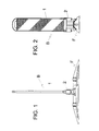
- the beacon B consists of an upper, plate-shaped part 1 and one lower part 2, designed as an open hollow body below, by screwing composed.
- the lower part 2 consists of a soft elastic Material, e.g. from rubber or from a rubbery one acting plastic.
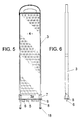
- the upper part 1 consists of a stiffer one Tool, preferably also made of plastic. These are an impact-resistant plastic that does not splinter down to -40 ° C.
- the upper part 1 is circumferential, on both sides over the plate 4 projecting flanges 3, 3a provided.
- the flanges 3, 3a serve the Stiffening of the plate 4.
- the plate 4 is at least on one side a film covered with a warning color and / or with a fluorescent color is equipped so that the beacon B looks good even in the dark is clearly recognizable.
- the lower flange 3a is wider than that on the sides of the plate 4 arranged flanges 3, the width of the lower flange 3a corresponds approximately to the width of the ceiling 2a of the lower part 2.
- the lower Part 2 is provided on the outside with reinforcing ribs 2b.
- the lower part 2 carries from the lower flange 3a projecting downwards Bars 5, each at their free ends in an arrow shape trained tip 6 leak.
- the width of the tip 6 is greater than the thickness of the web 5 in the remaining area.
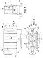
- the lower part 2 shown in FIGS. 7 to 9 is a with the Ceiling 2a formed at the top closed, but open at the bottom hollow body.
- the lower part has cutouts 17 on the narrow sides, one Form the target kink. In this area are on the broad sides of the Hollow body two approximately flat connecting webs 10 are provided.
- the recesses 17 have a height which is slightly less than that Distance between the two connecting webs 10.
- each hole 8 is an annular recess 14 arranged for receiving the collar 9.
- the bolts 8 passing through the bores 13 bear on their lower ends emerging from the reinforcement parts 12 each a screw nut 18, by tightening the screw connection is produced between the upper part 1 and the lower part 2.
- This screw connection can be released at any time, so that a replacement one of the two parts is easily possible if damaged.
Landscapes
- Engineering & Computer Science (AREA)
- Architecture (AREA)
- Civil Engineering (AREA)
- Structural Engineering (AREA)
- Road Signs Or Road Markings (AREA)
- Road Paving Structures (AREA)
- Refuge Islands, Traffic Blockers, Or Guard Fence (AREA)
- Carpets (AREA)
Description
- Fig. 1
- die Bake mit Fuß in der Seitenansicht;
- Fig. 2
- die Bake mit Fuß in der Vorderansicht;
- Fig. 3
- die Bake in der Vorderansicht im zusammengebauten Zustand;
- Fig. 4
- die Bake in der Seitenansicht im zusammengebauten Zustand;
- Fig. 5
- den oberen Teil der Bake in der Vorderansicht;
- Fig. 6
- den in Fig. 5 dargestellten oberen Teil in der Seitenansicht unter Weglassung der Schraubenbolzen;
- Fig. 7
- den unteren Teil der Bake in der Vorderansicht;
- Fig. 8
- den in Fig. 4 dargestellten unteren Teil in der Seitenansicht;
- Fig. 9
- den in den Fig. 7 und 8 dargestellten unteren Teil in der Draufsicht.
Claims (7)
- Bake mit Fuß als Leiteinrichtung für den Straßenverkehr, wobei die Bake, die über ihr unteres Ende mit dem Fuß lösbar gekuppelt ist, aus elastisch verformbarem Material besteht und im Bereich oberhalb ihrer Kupplung mit dem Fuß eine Soll-Knickstelle aufweist, welche dadurch gebildet ist, daß die in Form eines unten offenen Hohlkörpers ausgebildete Bake an ihren beiden Schmalseiten seitliche Ausschnitte aufweist,
dadurch gekennzeichnet, daß die Bake (B) aus einem unteren, aus weichelastischem Werkstoff bestehenden und die Soll-Knickstelle aufnehmenden Teil (2) und aus einem damit lösbar verbundenen, oberen Teil (1) besteht, welcher aus einem steiferen Werkstoff plattenförmig ausgebildet ist. - Bake nach Anspruch 1. dadurch gekennzeichnet, daß der plattenförmige obere Teil (1) umlaufende Flansche (3, 3a) aufweist.
- Bake nach Anspruch 1 oder 2, dadurch gekennzeichnet, daß der untere Teil (2) mit dem oberen Teil (1) verschraubt ist.
- Bake nach Anspruch 3, dadurch gekennzeichnet, daß die Verbindung der beiden Teile (1 und 2) durch in den oberen Teil (1) seitlich eingeformte Schraubenbolzen (8) besteht, welche Bohrungen (13) in seitlichen Verstärkungsteilen (12) des unteren Teils (2) durchdringen und an den freien, nach unten aus den Verstärkungsteilen (12) herausstehenden Enden jeweils mit einer Schraubenmutter (18) versehen sind.
- Bake nach einem der Ansprüche 1 bis 4, dadurch gekennzeichnet, daß der obere Teil (1) mindestens einen nach unten vorstehenden Steg (5) trägt, welcher unten eine pfeilförmig ausgebildete Spitze (6) aufweist, die in einen Schlitz (15) in der Decke (2a) des unteren Teils (2) eingreift, wobei der Schlitz (13) in Querrichtung eine geringere Abmessung aufweist als die Querausdehnung der pfeilförmigen Spitze (6).
- Bake nach Anspruch 5, dadurch gekennzeichnet, daß bei Anordnung mehrerer Stege (5) zwischen den mit diesen Stegen (5) zusammenwirkenden Schlitzen (15) jeweils eine im Inneren des unteren Teils (2) angeordnete Verstärkungsrippe (16) angeordnet ist.
- Bake nach einem der Ansprüche 4 bis 6. dadurch gekennzeichnet, daß am Austritt des Schraubenbolzens (8) aus dem oberen Teil (1) jeweils ein Kragen (9) angeordnet ist, der in eine entsprechende Ausnehmung (14) im unteren Teil (2) eingreift.
Priority Applications (1)
| Application Number | Priority Date | Filing Date | Title |
|---|---|---|---|
| SI9530319T SI0811092T1 (en) | 1995-02-24 | 1995-05-03 | Beacon with a base for use as a road traffic-direction system |
Applications Claiming Priority (3)
| Application Number | Priority Date | Filing Date | Title |
|---|---|---|---|
| DE29503161U | 1995-02-24 | ||
| DE29503161U DE29503161U1 (de) | 1995-02-24 | 1995-02-24 | Bake mit Fuß als Leiteinrichtung für den Straßenverkehr |
| PCT/EP1995/001682 WO1996026321A1 (de) | 1995-02-24 | 1995-05-03 | Bake mit fuss als leiteinrichtung für den strassenverkehr |
Publications (2)
| Publication Number | Publication Date |
|---|---|
| EP0811092A1 EP0811092A1 (de) | 1997-12-10 |
| EP0811092B1 true EP0811092B1 (de) | 1999-08-18 |
Family
ID=8004468
Family Applications (1)
| Application Number | Title | Priority Date | Filing Date |
|---|---|---|---|
| EP95919386A Expired - Lifetime EP0811092B1 (de) | 1995-02-24 | 1995-05-03 | Bake mit fuss als leiteinrichtung für den strassenverkehr |
Country Status (15)
| Country | Link |
|---|---|
| US (1) | US5670954A (de) |
| EP (1) | EP0811092B1 (de) |
| JP (1) | JPH11500502A (de) |
| AT (1) | ATE183565T1 (de) |
| AU (1) | AU2524395A (de) |
| CA (1) | CA2212178A1 (de) |
| CZ (1) | CZ291097B6 (de) |
| DE (2) | DE29503161U1 (de) |
| DK (1) | DK0811092T3 (de) |
| ES (1) | ES2137515T3 (de) |
| HU (1) | HU219102B (de) |
| SI (1) | SI0811092T1 (de) |
| SK (1) | SK284065B6 (de) |
| UA (1) | UA48163C2 (de) |
| WO (1) | WO1996026321A1 (de) |
Families Citing this family (20)
| Publication number | Priority date | Publication date | Assignee | Title |
|---|---|---|---|---|
| DE29516613U1 (de) * | 1995-10-20 | 1995-12-14 | Junker, Wilhelm, 71522 Backnang | Fuß für eine als Leiteinrichtung für den Straßenverkehr dienende Bake |
| US5775833A (en) * | 1996-06-19 | 1998-07-07 | Rotational Molding Of Utah | Collapsible, breakaway highway delineator |
| DE29719833U1 (de) * | 1997-11-07 | 1998-01-02 | Junker, Wilhelm, 71522 Backnang | Als Leiteinrichtung verwendbare Bake, insbesondere für den Straßenverkehr |
| CZ295591B6 (cs) * | 1997-11-07 | 2005-08-17 | Wilhelm Junker | Upozorňující sloupek, použitelný jako vodicí zařízení, zejména pro silniční provoz |
| US6659681B1 (en) | 1999-02-10 | 2003-12-09 | Traf Fix Devices, Inc. | Laterally stable vertical panel system |
| US6402422B1 (en) * | 1999-02-10 | 2002-06-11 | Traffix Devices, Inc. | Laterally stable vertical panel system |
| US6719484B1 (en) | 2002-11-15 | 2004-04-13 | Robert F. Johnson | Marker support |
| US7243450B2 (en) | 2004-08-09 | 2007-07-17 | Dicke Tool Company | Sign stand having resilient base |
| US7325999B1 (en) | 2005-03-02 | 2008-02-05 | Qwick Kurb, Inc. | Locking device for traffic beacon |
| US7730845B1 (en) * | 2006-03-07 | 2010-06-08 | Traffix Devices, Inc. | Vertical panel traffic channelizer |
| US7849617B2 (en) * | 2007-05-31 | 2010-12-14 | Energy Absorption Systems, Inc. | Self-righting post and method for the assembly and use thereof |
| USD620824S1 (en) * | 2009-10-09 | 2010-08-03 | Impact Recovery System, Inc. | Platform barrier for visually impaired pedestrians |
| USD620823S1 (en) * | 2009-10-09 | 2010-08-03 | Impact Recovery System, Inc. | Platform barrier for visually impaired pedestrians |
| USD620825S1 (en) * | 2009-10-19 | 2010-08-03 | Impact Recovery System, Inc. | Platform barrier for visually impaired pedestrians |
| JP5550451B2 (ja) * | 2010-05-26 | 2014-07-16 | 積水樹脂株式会社 | 視線誘導標 |
| JP2012188825A (ja) * | 2011-03-09 | 2012-10-04 | Sekisui Jushi Co Ltd | サイン標示体 |
| USD710723S1 (en) * | 2013-01-22 | 2014-08-12 | Jih Shin Enamel Co., Ltd. | Anti-dazzling board |
| CN105936238A (zh) * | 2015-11-05 | 2016-09-14 | 中山汇尔吉自动化设备有限公司 | 多层塔形伸缩警示筒 |
| CN107237278A (zh) * | 2017-07-05 | 2017-10-10 | 陈魏魏 | 施工区使用的新型警示标牌 |
| CN108914810A (zh) * | 2018-07-02 | 2018-11-30 | 安徽昂然节能环保科技有限公司 | 一种可拆卸式道路交通信息指示牌 |
Family Cites Families (13)
| Publication number | Priority date | Publication date | Assignee | Title |
|---|---|---|---|---|
| DE380062C (de) * | 1923-09-01 | Wilhelm Bergmann Dr | Krankenbett | |
| DE2309249A1 (de) * | 1973-02-24 | 1974-08-29 | Kurt Konrad Gustav Karl Nagl | Standsaeule mit verformungseinrichtung |
| US4004545A (en) * | 1975-03-20 | 1977-01-25 | G.L.P. Company | Boundary marker |
| US4084914A (en) * | 1977-01-28 | 1978-04-18 | Humphrey William D | Self-erecting highway guide post |
| AU5013679A (en) * | 1979-08-21 | 1981-02-26 | Nylex Corporation Limited | Traffic sign |
| US4343567A (en) * | 1980-02-27 | 1982-08-10 | Robert D. Cunningham | Self-erecting roadway marking post |
| US4611949A (en) * | 1981-10-14 | 1986-09-16 | Carsonite International Corporation, A Division Of Ametek | Detachable base for road delineators |
| SE428814B (sv) * | 1981-11-27 | 1983-07-25 | John Bjorlund | Sjelvresande stolpe |
| EP0200659A1 (de) * | 1985-04-22 | 1986-11-05 | Christian Aguera | Hohlstange zur Markierung von Skipisten, Sportfeldern usw. |
| JP2695041B2 (ja) * | 1989-01-23 | 1997-12-24 | ユンカー,ヴイルヘルム | 誘導装置 |
| US5165818A (en) * | 1991-03-05 | 1992-11-24 | Rretex, Inc. | Traffic directing sign |
| US5273371A (en) * | 1992-07-06 | 1993-12-28 | Hugron Denis P | Signalling post |
| US5452965A (en) * | 1994-05-09 | 1995-09-26 | Flexstake, Inc. | Replaceable flexible marker |
-
1995
- 1995-02-24 DE DE29503161U patent/DE29503161U1/de not_active Expired - Lifetime
- 1995-03-05 UA UA97074121A patent/UA48163C2/uk unknown
- 1995-04-03 US US08/415,271 patent/US5670954A/en not_active Expired - Lifetime
- 1995-05-03 AU AU25243/95A patent/AU2524395A/en not_active Abandoned
- 1995-05-03 SI SI9530319T patent/SI0811092T1/xx not_active IP Right Cessation
- 1995-05-03 WO PCT/EP1995/001682 patent/WO1996026321A1/de not_active Ceased
- 1995-05-03 CA CA002212178A patent/CA2212178A1/en not_active Abandoned
- 1995-05-03 CZ CZ19972462A patent/CZ291097B6/cs not_active IP Right Cessation
- 1995-05-03 ES ES95919386T patent/ES2137515T3/es not_active Expired - Lifetime
- 1995-05-03 EP EP95919386A patent/EP0811092B1/de not_active Expired - Lifetime
- 1995-05-03 JP JP8525325A patent/JPH11500502A/ja active Pending
- 1995-05-03 HU HU9800405A patent/HU219102B/hu not_active IP Right Cessation
- 1995-05-03 SK SK1149-97A patent/SK284065B6/sk unknown
- 1995-05-03 DK DK95919386T patent/DK0811092T3/da active
- 1995-05-03 DE DE59506652T patent/DE59506652D1/de not_active Expired - Lifetime
- 1995-05-03 AT AT95919386T patent/ATE183565T1/de not_active IP Right Cessation
Also Published As
| Publication number | Publication date |
|---|---|
| EP0811092A1 (de) | 1997-12-10 |
| HUT77585A (hu) | 1998-06-29 |
| SK284065B6 (sk) | 2004-09-08 |
| US5670954A (en) | 1997-09-23 |
| UA48163C2 (uk) | 2002-08-15 |
| CZ291097B6 (cs) | 2002-12-11 |
| SI0811092T1 (en) | 1999-12-31 |
| ATE183565T1 (de) | 1999-09-15 |
| JPH11500502A (ja) | 1999-01-12 |
| CA2212178A1 (en) | 1996-08-29 |
| SK114997A3 (en) | 1998-04-08 |
| AU2524395A (en) | 1996-09-11 |
| DK0811092T3 (da) | 2000-03-06 |
| DE29503161U1 (de) | 1995-04-20 |
| ES2137515T3 (es) | 1999-12-16 |
| CZ246297A3 (cs) | 1998-02-18 |
| WO1996026321A1 (de) | 1996-08-29 |
| HU219102B (hu) | 2001-02-28 |
| DE59506652D1 (de) | 1999-09-23 |
Similar Documents
| Publication | Publication Date | Title |
|---|---|---|
| EP0811092B1 (de) | Bake mit fuss als leiteinrichtung für den strassenverkehr | |
| EP0363725B1 (de) | Siebboden | |
| WO1997015728A1 (de) | Fuss für eine als leiteinrichtung für den strassenverkehr dienende bake | |
| CH636663A5 (en) | Road barrier device for keeping vehicles on a road | |
| DE20106675U1 (de) | Schutzplankenanordnung für von Bäumen oder vergleichbaren Gegenständen gesäumte Fahrwege für Kraftfahrzeuge | |
| DE4032731C2 (de) | Auflage für zweiseitig wirkende Fertigteile einer Gleit- oder Schutzplankenvorrichtung für Verkehrswege | |
| DE29804162U1 (de) | Als Leiteinrichtung verwendbare Bake, insbesondere für den Straßenverkehr | |
| EP0009235B1 (de) | Bakenständer | |
| DE4335904C2 (de) | Passive Schutzeinrichtung an Straßen | |
| DE3016884A1 (de) | Bakenstaender | |
| DE2706277C3 (de) | Siebboden | |
| DE19539274C2 (de) | Ablenkschwelle | |
| EP0687790B1 (de) | Linearverbinder für hohle Abstandsprofile eines Mehrscheibenisolierglases | |
| AT397831B (de) | Stahltürzarge mit schwellenprofil | |
| EP1034333B1 (de) | Als leiteinrichtung verwendbare bake, insbesondere für den strassenverkehr | |
| DE69102404T2 (de) | Bodenrinnenrost und Verbindungsvorrichtung dafür. | |
| EP0337461B1 (de) | Firstentlüftungssystem | |
| DE29621149U1 (de) | Bake für den Straßenverkehr | |
| DE2949541C2 (de) | Bakenständer | |
| EP0583684B1 (de) | Tragplatte für Brücken und Rampen | |
| EP0666376A2 (de) | Leitwand für Kraftfahrzeuge | |
| EP0819577B1 (de) | Warndreieck | |
| DE8912563U1 (de) | Leiteinrichtung | |
| DE4305827A1 (de) | Lenkstockschalter für Kraftfahrzeuge | |
| DE9413049U1 (de) | Vorrichtung zum Befestigen einer Abdeckleiste für Nuten von Kraftwagen-Aufbauten |
Legal Events
| Date | Code | Title | Description |
|---|---|---|---|
| PUAI | Public reference made under article 153(3) epc to a published international application that has entered the european phase |
Free format text: ORIGINAL CODE: 0009012 |
|
| 17P | Request for examination filed |
Effective date: 19970904 |
|
| AK | Designated contracting states |
Kind code of ref document: A1 Designated state(s): AT BE CH DE DK ES FR GB IT LI NL PT |
|
| AX | Request for extension of the european patent |
Free format text: SI PAYMENT 970904 |
|
| GRAG | Despatch of communication of intention to grant |
Free format text: ORIGINAL CODE: EPIDOS AGRA |
|
| 17Q | First examination report despatched |
Effective date: 19980714 |
|
| GRAG | Despatch of communication of intention to grant |
Free format text: ORIGINAL CODE: EPIDOS AGRA |
|
| GRAH | Despatch of communication of intention to grant a patent |
Free format text: ORIGINAL CODE: EPIDOS IGRA |
|
| GRAH | Despatch of communication of intention to grant a patent |
Free format text: ORIGINAL CODE: EPIDOS IGRA |
|
| GRAA | (expected) grant |
Free format text: ORIGINAL CODE: 0009210 |
|
| AK | Designated contracting states |
Kind code of ref document: B1 Designated state(s): AT BE CH DE DK ES FR GB IT LI NL PT |
|
| AX | Request for extension of the european patent |
Free format text: SI PAYMENT 19970904 |
|
| REF | Corresponds to: |
Ref document number: 183565 Country of ref document: AT Date of ref document: 19990915 Kind code of ref document: T |
|
| REG | Reference to a national code |
Ref country code: CH Ref legal event code: NV Representative=s name: LUCHS & PARTNER PATENTANWAELTE Ref country code: CH Ref legal event code: EP |
|
| GBT | Gb: translation of ep patent filed (gb section 77(6)(a)/1977) |
Effective date: 19990818 |
|
| REF | Corresponds to: |
Ref document number: 59506652 Country of ref document: DE Date of ref document: 19990923 |
|
| ITF | It: translation for a ep patent filed | ||
| REG | Reference to a national code |
Ref country code: ES Ref legal event code: FG2A Ref document number: 2137515 Country of ref document: ES Kind code of ref document: T3 |
|
| ET | Fr: translation filed | ||
| REG | Reference to a national code |
Ref country code: PT Ref legal event code: SC4A Free format text: AVAILABILITY OF NATIONAL TRANSLATION Effective date: 19990927 |
|
| REG | Reference to a national code |
Ref country code: DK Ref legal event code: T3 |
|
| PLBE | No opposition filed within time limit |
Free format text: ORIGINAL CODE: 0009261 |
|
| STAA | Information on the status of an ep patent application or granted ep patent |
Free format text: STATUS: NO OPPOSITION FILED WITHIN TIME LIMIT |
|
| 26N | No opposition filed | ||
| REG | Reference to a national code |
Ref country code: GB Ref legal event code: IF02 |
|
| PGFP | Annual fee paid to national office [announced via postgrant information from national office to epo] |
Ref country code: PT Payment date: 20030515 Year of fee payment: 9 |
|
| PG25 | Lapsed in a contracting state [announced via postgrant information from national office to epo] |
Ref country code: PT Free format text: LAPSE BECAUSE OF NON-PAYMENT OF DUE FEES Effective date: 20041103 |
|
| REG | Reference to a national code |
Ref country code: SI Ref legal event code: IF |
|
| REG | Reference to a national code |
Ref country code: PT Ref legal event code: MM4A Effective date: 20041103 |
|
| PGFP | Annual fee paid to national office [announced via postgrant information from national office to epo] |
Ref country code: NL Payment date: 20070516 Year of fee payment: 13 |
|
| PGFP | Annual fee paid to national office [announced via postgrant information from national office to epo] |
Ref country code: DK Payment date: 20070524 Year of fee payment: 13 Ref country code: BE Payment date: 20070524 Year of fee payment: 13 |
|
| PGFP | Annual fee paid to national office [announced via postgrant information from national office to epo] |
Ref country code: ES Payment date: 20070525 Year of fee payment: 13 |
|
| PGFP | Annual fee paid to national office [announced via postgrant information from national office to epo] |
Ref country code: GB Payment date: 20070523 Year of fee payment: 13 |
|
| PGFP | Annual fee paid to national office [announced via postgrant information from national office to epo] |
Ref country code: FR Payment date: 20070518 Year of fee payment: 13 |
|
| BERE | Be: lapsed |
Owner name: *JUNKER WILHELM Effective date: 20080531 |
|
| REG | Reference to a national code |
Ref country code: DK Ref legal event code: EBP |
|
| GBPC | Gb: european patent ceased through non-payment of renewal fee |
Effective date: 20080503 |
|
| PG25 | Lapsed in a contracting state [announced via postgrant information from national office to epo] |
Ref country code: NL Free format text: LAPSE BECAUSE OF NON-PAYMENT OF DUE FEES Effective date: 20081201 |
|
| REG | Reference to a national code |
Ref country code: FR Ref legal event code: ST Effective date: 20090119 |
|
| PG25 | Lapsed in a contracting state [announced via postgrant information from national office to epo] |
Ref country code: BE Free format text: LAPSE BECAUSE OF NON-PAYMENT OF DUE FEES Effective date: 20080531 |
|
| PG25 | Lapsed in a contracting state [announced via postgrant information from national office to epo] |
Ref country code: FR Free format text: LAPSE BECAUSE OF NON-PAYMENT OF DUE FEES Effective date: 20080602 Ref country code: DK Free format text: LAPSE BECAUSE OF NON-PAYMENT OF DUE FEES Effective date: 20080531 |
|
| PG25 | Lapsed in a contracting state [announced via postgrant information from national office to epo] |
Ref country code: GB Free format text: LAPSE BECAUSE OF NON-PAYMENT OF DUE FEES Effective date: 20080503 |
|
| REG | Reference to a national code |
Ref country code: ES Ref legal event code: FD2A Effective date: 20080505 |
|
| PGFP | Annual fee paid to national office [announced via postgrant information from national office to epo] |
Ref country code: IT Payment date: 20090529 Year of fee payment: 15 Ref country code: AT Payment date: 20090528 Year of fee payment: 15 |
|
| PG25 | Lapsed in a contracting state [announced via postgrant information from national office to epo] |
Ref country code: ES Free format text: LAPSE BECAUSE OF NON-PAYMENT OF DUE FEES Effective date: 20080505 |
|
| PG25 | Lapsed in a contracting state [announced via postgrant information from national office to epo] |
Ref country code: AT Free format text: LAPSE BECAUSE OF NON-PAYMENT OF DUE FEES Effective date: 20100503 |
|
| PG25 | Lapsed in a contracting state [announced via postgrant information from national office to epo] |
Ref country code: IT Free format text: LAPSE BECAUSE OF NON-PAYMENT OF DUE FEES Effective date: 20100503 |
|
| PGFP | Annual fee paid to national office [announced via postgrant information from national office to epo] |
Ref country code: CH Payment date: 20140523 Year of fee payment: 20 Ref country code: DE Payment date: 20140602 Year of fee payment: 20 |
|
| REG | Reference to a national code |
Ref country code: DE Ref legal event code: R071 Ref document number: 59506652 Country of ref document: DE |
|
| REG | Reference to a national code |
Ref country code: CH Ref legal event code: PL |