EP0811143B1 - Umlaufender regenerativer wärmetauscher und verfahren zum betreiben eines umlaufendes regeneratives wärmetauschers - Google Patents
Umlaufender regenerativer wärmetauscher und verfahren zum betreiben eines umlaufendes regeneratives wärmetauschers Download PDFInfo
- Publication number
- EP0811143B1 EP0811143B1 EP96904422A EP96904422A EP0811143B1 EP 0811143 B1 EP0811143 B1 EP 0811143B1 EP 96904422 A EP96904422 A EP 96904422A EP 96904422 A EP96904422 A EP 96904422A EP 0811143 B1 EP0811143 B1 EP 0811143B1
- Authority
- EP
- European Patent Office
- Prior art keywords
- front surface
- gas
- heat exchanger
- rotor
- rotary regenerative
- Prior art date
- Legal status (The legal status is an assumption and is not a legal conclusion. Google has not performed a legal analysis and makes no representation as to the accuracy of the status listed.)
- Expired - Lifetime
Links
- 230000001172 regenerating effect Effects 0.000 title claims description 14
- 238000000034 method Methods 0.000 title claims description 4
- OKTJSMMVPCPJKN-UHFFFAOYSA-N Carbon Chemical compound [C] OKTJSMMVPCPJKN-UHFFFAOYSA-N 0.000 description 8
- 238000005299 abrasion Methods 0.000 description 5
- 229910052799 carbon Inorganic materials 0.000 description 4
- 229910002804 graphite Inorganic materials 0.000 description 4
- 239000010439 graphite Substances 0.000 description 4
- 239000000919 ceramic Substances 0.000 description 3
- 238000005096 rolling process Methods 0.000 description 3
- 238000009826 distribution Methods 0.000 description 2
- 238000005461 lubrication Methods 0.000 description 2
- 238000004519 manufacturing process Methods 0.000 description 2
- 239000002253 acid Substances 0.000 description 1
- 230000015556 catabolic process Effects 0.000 description 1
- 230000001419 dependent effect Effects 0.000 description 1
- 230000000694 effects Effects 0.000 description 1
- 230000001050 lubricating effect Effects 0.000 description 1
- 238000012423 maintenance Methods 0.000 description 1
- 239000002245 particle Substances 0.000 description 1
- 230000000284 resting effect Effects 0.000 description 1
- 238000007789 sealing Methods 0.000 description 1
- 238000009827 uniform distribution Methods 0.000 description 1
Images


Classifications
-
- F—MECHANICAL ENGINEERING; LIGHTING; HEATING; WEAPONS; BLASTING
- F28—HEAT EXCHANGE IN GENERAL
- F28D—HEAT-EXCHANGE APPARATUS, NOT PROVIDED FOR IN ANOTHER SUBCLASS, IN WHICH THE HEAT-EXCHANGE MEDIA DO NOT COME INTO DIRECT CONTACT
- F28D19/00—Regenerative heat-exchange apparatus in which the intermediate heat-transfer medium or body is moved successively into contact with each heat-exchange medium
- F28D19/04—Regenerative heat-exchange apparatus in which the intermediate heat-transfer medium or body is moved successively into contact with each heat-exchange medium using rigid bodies, e.g. mounted on a movable carrier
- F28D19/047—Sealing means
Definitions
- the present invention in a first aspect relates to a rotary regenerative heat exchanger of the kind specified in the preamble of claim 1 and in a second aspect to a method for operating such heat exchanger as specified in the preamble of claim 8.
- SE 176 375 discloses a rotary regenerative heat exchanger with a support in the form of rolling bodies, mounted in the outer ends of sector-shaped plates closed to both ends of the rotating part and rolling on a flange along the periphery at the top and bottom end of the rotor.
- WO94/01730 an improvement is disclosed by using sliding shoes of carbon or graphite instead of ceramic sliding shoes.
- a sliding shoe eliminates the drawbacks with a sliding shoe of ceramics.
- graphite has excellent lubrication properties and like carbon has an ability to maintain the flanges of the rotating body clean when adhering a lubricating layer of carbon or graphite on the flanges.
- the abrasion of the sliding shoe also secures a correct contact with parallel contact surfaces so that the contact takes place on the complete sliding shoe surface.
- Carbon and graphite also have a good acceptance of the high temperature and the acid environment that are present. By the abrasion of the sliding shoes they will gradually be consumed and have to be replaced.
- the object of the present invention therefore is to attain a regenerative heat exchanger of the kind in question in which the number of sliding shoes is as small as possible.
- the device according to the invention thus deviates from the traditional concept of using two or more supports for the sector plate, when supports of the non-contacting type are used.
- the problem of avoiding tilting is overcome in that the support is elongated so that the outer part of the sector plate is stabilized in the circumferential direction.
- the number of devices for establishing gas cushions is reduced to the half, which lowers the manufacturing and maintenance costs and reduces the risk for failure.
- the air cushion Due to the elongated shape, the air cushion will have a larger circumferential extension, and the area of the air cushion can be increased. Thereby a sufficient raising force from the air cushion can be attained at a lower pressure of the supplied gas in comparison with a conventional pair of circular air cushions. Since the requirement on the pressure level of the gas source thus will be lower, the running costs for the gas supply is reduced.
- the angular extension of the front surface preferably is more than half the angular extension of the sector plate in order to attain a sufficiently stabilized support by the air cushion and it should preferably be symmetrically located.
- the gas outlet has a corresponding elongated shape, whereby a uniform distribution of the gas is promoted.
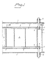
- the heat exchanger illustrated in fig. 1 is of conventional type having a stationary casing 1 and a cylindrical rotor 2 containing the regenerative mass 3.
- the rotor has a hub 4 and an upper fixed sector shaped centre plate 5 with a movable sector plate 6 pivotally connected thereto and corresponding lower fixed centre plate 7 and movable sector plate 8.
- the two sets of plates 5, 6 and 7, 8 have the function to seal against the upper and lower ends of the rotor 2 as tight as possible and thereby separate the heat exchanging media flowing to and from the rotor through axial openings connected to media ducts (not shown).
- each of the movable sector plates 6, 8 are provided a device, which device forms support means 10 for maintaining a certain clearances between the ends of the sector plates 6, 8 and an upper and lower annular edge flange 12 attached to the rotor along its upper and lower peripheries, each flange having an outer circumferentially continuous end surface 61 for co-operation with a front surface 62 connected to each of the devices 10.
- the sector plate 6 is seen from the outside and co-operates with the end surface 11 of the rotor end flange 9.
- pressure gas is supplied to a sliding shoe forming gas cushion means with a front surface facing the end surface 11 of the flange 9.
- the front surface 12 of the sliding shoe is arc-shaped and limited by two concentric circular arcs 14 and 15.
- the sliding shoe is symmetrically arranged in relation to a symmetry line 19 of the sector plate 6 and extends along the flange 9 about two thirds of the angular extension of the sector plate.
- the gas supplied through the sleeve 15 is distributed through channels in the sliding shoe to an arc-shaped groove 16 in the front surface 12 of the sliding shoe, and creates an air cushion between the front surface 12 of the sliding shoe and the end surface 11 of the flange 9. Although only one gas cushion supports the sector plate 6 the support will be stable and without risk for tilting due to the elongated shape of the gas cushion.
- Fig. 3 illustrates the support 10 through a section therethrough.
- the arc-shaped sliding shoe 17 is rigidly attached to the sector plate 6 and projects a short distance from the internal surface 28 of the sector plate 6.
- the groove 16 forming the gas outlet means extends along almost the entire length of the front surface. Through a plurality of channels 27 the groove 16 communicates with the opposite side of the sliding shoe. This side is covered by a closure member 18 of the same shape as the sliding shoe 17.
- the closure member has a gas inlet opening 25 and a distribution groove 26 through which the inlet opening 25 and the channels 27 communicate.
- a circular sleeve 15 is attached to the closure member 18 around the gas inlet opening 25, which sleeve extends out through a circular hole in the casing 1, and the opposite end of the sleeve 15 is through a gas conduit 23 connected to a pressure gas source 22. Between a flange 20 attached to the sleeve 15 and the casing 1 a sealing bellow 21 is provided, so that a predetermined axial force will be applied downwards on the plate 6 due to the spring effect of the bellow 21.
- pressure gas flows through conduit 23, the interior 24 of the sleeve 15, the inlet opening 25, the distribution groove 26 and the channels 27 to the groove 16.
- the pressure of the gas keeps the front surface 12 of the sliding shoe 17 raised from the end surface 11 of the flange 9 against the action of the force from the bellow 21, so that the gas is allowed to escape through these surfaces, thereby creating the elongated air cushion.
- Fig. 6 illustrates an alternative embodiment of the support 10, in which the front surface 12"' co-operating with the end surface 11 of the flange 9 is formed by a part of the inner surface 28 of the sector plate 6.
- the clearance S between the sector plate 6 and the end flange thereby will be more narrow.
- the groove 12' extends circumferentially almost to the ends of the sector plate so that the air cushion will receive a corresponding extension.
- Figs. 3 and 4 illustrate alternative shapes ofthe front surface 12', 12", respectively.
- the front surface 12' is rectangular, limited by two straight lines 13', 14', and in fig. 4 the front surface is crescent-shaped, limited by two non-concentric circular arcs 13", 14".
Landscapes
- Engineering & Computer Science (AREA)
- Physics & Mathematics (AREA)
- Thermal Sciences (AREA)
- Mechanical Engineering (AREA)
- General Engineering & Computer Science (AREA)
- Heat-Exchange Devices With Radiators And Conduit Assemblies (AREA)
- Treatment Of Fiber Materials (AREA)
Claims (8)
- Rotierender, regenerativer Wärmetauscher mit einem im wesentlichen zylindrischen Rotor (2), der in einem Gehäuse (1) montiert ist und an wenigstens einem seiner Enden mit einer über den Umfang durchgängigen äußeren Endfläche(11) versehen ist, wobei das Gehäuse (1) an wenigstens einem der Rotorenden mit Platten (5, 6, 7, 8) mit im wesentlichen senkrecht zur Achse des Rotors (2) liegender Ausrichtung nahe des zugehörigen Rotorendes versehen ist, die bewegliche Sektorplatten (6, 8) aufweisen, die durch eine resultierende Axialkraft in Richtung des zugehörigen Rotorendes beaufschlagt und zur Aufrechterhaltung eines bestimmten Spiels (S) zwischen den Sektorplatten (6, 8) und dem zugehörigen Rotorende mit Stützmitteln (1C) versehen sind, die Gaskissenmittel (17) aufweisen, die jeweils eine Frontfläche (12) besitzen, die der Endfläche (11) zugewandt ist und Gasauslaßmittel (16) aufweist, die durch Gasleitungsmittel (23, 24, 25, 26, 27) mit einer Druckgasquelle (22) mit einem Druck in Verbindung stehen, der ausreichend ist, um einen Spalt zwischen der Frontfläche (12) und der Endfläche (11) gegen die Wirkung der Axialkraft aufzubauen, wodurch ein Gaskissen zwischen der Frontfläche (12) und der Endfläche (11) entsteht, da das Gas aus den Gasauslaßmitteln (16) durch den Spalt austritt, dadurch gekennzeichnet, daß die Stützmittel (10) wenigstens einer der Sektorplatten (6, 8) aus einzelnen, alleinigen Gaskissenmitteln (17) bestehen und daß die Frontfläche (12) der Gaskissenmittel eine Langform besitzt, deren längere Erstreckung über den Umfang entlang der Endfläche (11) ausgerichtet ist.
- Rotierender, regenerativer Wärmetauscher nach Anspruch 1, dadurch gekennzeichnet, daß die Frontfläche (12) durch zwei konzentrische Kreisbögen (13, 14) radial begrenzt ist und im wesentlichen eine Wurstform besitzt.
- Rotierender, regenerativer Wärmetauscher nach Anspruch 1, dadurch gekennzeichnet, daß die Frontfläche (12') radial durch zwei parallele, gerade Kanten (13', 14') begrenzt ist und eine im wesentlichen rechteckige Form besitzt.
- Rotierender, regenerativer Wärmetauscher nach Anspruch 1, dadurch gekennzeichnet, daß die Frontfläche (12") radial durch zwei nicht konzentrische Kreisbögen (13", 14") begrenzt ist und im wesentlichen eine Sichelform besitzt.
- Rotierender, regenerativer Wärmetauscher nach einem der Ansprüche 1 bis 4, dadurch gekennzeichnet, daß die Winkelerstreckung der Frontfläche (12) mehr als die Hälfte der Winkelerstreckung der Sektorplatte (6, 8) beträgt und die Frontfläche (12) symmetrisch mit Bezug auf eine radiale Symmetrielinie (19) in der Fläche der Sektorplatte (6, 8) angeordnet ist.
- Rotierender, regenerativer Wärmetauscher nach einem der Ansprüche 1 bis 5, dadurch gekennzeichnet, daß die Gasauslaßmittel (16) aus einer Nut bestehen, die sich in der Längsrichtung der Frontfläche (12) erstreckt.
- Rotierender, regenerativer Wärmetauscher nach Anspruch 1 oder 2, dadurch gekennzeichnet, daß die Frontfläche (12"') ein Teil einer inneren Fläche (28) der Sektorplatte (6, 8) ist.
- Verfahren zum Betreiben eines rotierenden, regenerativen Wärmetauschers, um ein bestimmtes Spiel (S) zwischen einem Ende eines im wesentlichen zylindrischen Rotors (2) des Wärmetauschers und einer nahe des Rotors angeordneten beweglichen Sektorplatte (6, 8) in einer Richtung im wesentlichen senkrecht zur Achse des Rotors (2) aufrechtzuerhalten, wobei das Rotorende eine über den Umfang durchgängige äußere Endfläche (11) besitzt, der Rotor (2) in einem Gehäuse (1) montiert ist, die Sektorplatte (6, 8) mit dem Gehäuse verbunden und durch eine resultierende Axialkraft in Richtung des Rotorendes beaufschlagt ist, und das Spiel (S) durch Zuführen von Gas zu an der Sektorplatte (6, 8) befindlichen Stützmitteln (10) aufrechterhalten wird, die Gaskissenmittel (17) mit einer der Endfläche (11) zugewandten Frontfläche (12) mit Gasauslaßmitteln (16) aufweist, wobei der Druck des zugeführten Gases ausreichend ist, einen Spalt zwischen der Frontfläche (12) und der Endfläche (11) gegen die Wirkung der Axialkraft aufzubauen, wodurch ein Gaskissen zwischen der Frontfläche (12) und der Endfläche (11) erzeugt wird, da das Gas von den Gasauslaßmitteln (16) durch den Spalt ausströmt, dadurch gekennzeichnet, daß das Gas einzelnen, alleinigen Stützmitteln (10) zugeführt wird und diese einzelnen Stützmittel (10) so angeordnet werden, daß sie ein langförmiges Gaskissen bilden, dessen längere Erstreckung über den Umfang entlang der Endfläche (11) ausgerichtet ist.
Applications Claiming Priority (3)
| Application Number | Priority Date | Filing Date | Title |
|---|---|---|---|
| SE9500681A SE504019C2 (sv) | 1995-02-24 | 1995-02-24 | Roterande regenerativ värmeväxlare och sätt att styra en sådan värmeväxlare |
| SE9500681 | 1995-02-24 | ||
| PCT/SE1996/000232 WO1996026407A1 (en) | 1995-02-24 | 1996-02-21 | Rotary regenerative heat exchanger and a method for operating such heat exchanger |
Publications (2)
| Publication Number | Publication Date |
|---|---|
| EP0811143A1 EP0811143A1 (de) | 1997-12-10 |
| EP0811143B1 true EP0811143B1 (de) | 1999-11-24 |
Family
ID=20397345
Family Applications (1)
| Application Number | Title | Priority Date | Filing Date |
|---|---|---|---|
| EP96904422A Expired - Lifetime EP0811143B1 (de) | 1995-02-24 | 1996-02-21 | Umlaufender regenerativer wärmetauscher und verfahren zum betreiben eines umlaufendes regeneratives wärmetauschers |
Country Status (8)
| Country | Link |
|---|---|
| EP (1) | EP0811143B1 (de) |
| CZ (1) | CZ288346B6 (de) |
| DE (1) | DE69605287T2 (de) |
| DK (1) | DK0811143T3 (de) |
| HU (1) | HU220316B (de) |
| PL (1) | PL321714A1 (de) |
| SE (1) | SE504019C2 (de) |
| WO (1) | WO1996026407A1 (de) |
Cited By (1)
| Publication number | Priority date | Publication date | Assignee | Title |
|---|---|---|---|---|
| US6749815B2 (en) | 2001-05-04 | 2004-06-15 | Megtec Systems, Inc. | Switching valve seal |
Families Citing this family (4)
| Publication number | Priority date | Publication date | Assignee | Title |
|---|---|---|---|---|
| US6261092B1 (en) | 2000-05-17 | 2001-07-17 | Megtec Systems, Inc. | Switching valve |
| US7325562B2 (en) | 2002-05-07 | 2008-02-05 | Meggec Systems, Inc. | Heated seal air for valve and regenerative thermal oxidizer containing same |
| US6669472B1 (en) | 2002-08-28 | 2003-12-30 | Megtec Systems, Inc. | Dual lift system |
| US7150446B1 (en) | 2002-08-28 | 2006-12-19 | Megtec Systems, Inc. | Dual lift system |
Family Cites Families (7)
| Publication number | Priority date | Publication date | Assignee | Title |
|---|---|---|---|---|
| DE973548C (de) * | 1952-09-16 | 1960-03-24 | Babcock & Wilcox Dampfkessel W | Umlaufender Regenerativ-Vorwaermer fuer Gas, Luft od. dgl. |
| US3122200A (en) * | 1960-05-24 | 1964-02-25 | Koch Jakob | Dynamic sealing means for rotary regenerative heat exchangers |
| US3232335A (en) * | 1962-03-21 | 1966-02-01 | Svenska Rotor Maskiner Ab | Rotary regenerative preheater |
| US3499480A (en) * | 1968-09-10 | 1970-03-10 | Air Preheater | Flame seals |
| GB9206136D0 (en) * | 1992-03-20 | 1992-05-06 | Wes Technology Inc | Modifications to air heaters |
| DK168649B1 (da) * | 1992-07-07 | 1994-05-09 | Burmeister & Wains Energi | Regenerativ varmeveksler |
| EP0715706B1 (de) * | 1993-07-02 | 1999-05-19 | Berndt Lindström | Regenerativ-wärmetauscher |
-
1995
- 1995-02-24 SE SE9500681A patent/SE504019C2/sv not_active IP Right Cessation
-
1996
- 1996-02-21 DE DE69605287T patent/DE69605287T2/de not_active Expired - Fee Related
- 1996-02-21 EP EP96904422A patent/EP0811143B1/de not_active Expired - Lifetime
- 1996-02-21 CZ CZ19972664A patent/CZ288346B6/cs not_active IP Right Cessation
- 1996-02-21 DK DK96904422T patent/DK0811143T3/da active
- 1996-02-21 WO PCT/SE1996/000232 patent/WO1996026407A1/en not_active Ceased
- 1996-02-21 HU HU9801281A patent/HU220316B/hu not_active IP Right Cessation
- 1996-02-21 PL PL96321714A patent/PL321714A1/xx unknown
Cited By (2)
| Publication number | Priority date | Publication date | Assignee | Title |
|---|---|---|---|---|
| US6749815B2 (en) | 2001-05-04 | 2004-06-15 | Megtec Systems, Inc. | Switching valve seal |
| US6899121B2 (en) | 2001-05-04 | 2005-05-31 | Megtec Systems Inc. | Switching valve seal |
Also Published As
| Publication number | Publication date |
|---|---|
| SE504019C2 (sv) | 1996-10-21 |
| DK0811143T3 (da) | 2000-05-15 |
| SE9500681L (sv) | 1996-08-25 |
| SE9500681D0 (sv) | 1995-02-24 |
| PL321714A1 (en) | 1997-12-22 |
| WO1996026407A1 (en) | 1996-08-29 |
| DE69605287D1 (de) | 1999-12-30 |
| CZ288346B6 (en) | 2001-05-16 |
| DE69605287T2 (de) | 2000-07-20 |
| HUP9801281A2 (hu) | 1998-08-28 |
| HUP9801281A3 (en) | 1999-11-29 |
| HU220316B (hu) | 2001-12-28 |
| CZ266497A3 (en) | 1997-11-12 |
| EP0811143A1 (de) | 1997-12-10 |
Similar Documents
| Publication | Publication Date | Title |
|---|---|---|
| US5137078A (en) | Air heater seals | |
| AU745295B2 (en) | Roller arrangement for a product to be coated in a molten metal bath | |
| JPS648205B2 (de) | ||
| US4440077A (en) | Press roller with adjustable bending characteristics | |
| EP0807238B1 (de) | Umlaufender regenerativer wärmetauscher und verfahren zum betreiben eines umlaufenden regenerativen wärmetauschers | |
| JPS5918568B2 (ja) | ロ−ル装置 | |
| US5338279A (en) | Hydrostatically supported sag-compensation roll, in particular for paper manufacturing machines | |
| WO1996026407A1 (en) | Rotary regenerative heat exchanger and a method for operating such heat exchanger | |
| EP0830514A1 (de) | Kippsegmentlager | |
| WO1997049941A1 (en) | Perimeter sealing element for regenerative heat exchanger | |
| WO1997049941A9 (en) | Perimeter sealing element for regenerative heat exchanger | |
| CA1158272A (en) | Seal assembly for a rotary kiln | |
| EP0807237B1 (de) | Regenerativer wärmetauscher und verfahren zum betreiben eines regenerativen wärmetauschers | |
| HUP0102918A2 (hu) | Készülék forgó regeneratív hőcserélőhöz | |
| FI78526C (fi) | Roterande foerbindning. | |
| US4925014A (en) | Transport roller for glass cooling passages | |
| EP0824664B1 (de) | Umlaufender regenerativer wärmetauscher mit gleitschuhen | |
| US5038849A (en) | Sealing of air heaters by deforming sector plates | |
| WO1995000809A1 (en) | Regenerative heat exchanger | |
| JPH10196801A (ja) | 軸シール | |
| CN102216663B (zh) | 驱动单元 | |
| US4372371A (en) | Trunnion air seal | |
| JP4718774B2 (ja) | ジャーナルベアリングを有するハブシール回転継手 | |
| JP2740049B2 (ja) | ロールを駆動する方法及び対応のロール | |
| CN113653803B (zh) | 轴封结构和具有其的燃气轮机 |
Legal Events
| Date | Code | Title | Description |
|---|---|---|---|
| PUAI | Public reference made under article 153(3) epc to a published international application that has entered the european phase |
Free format text: ORIGINAL CODE: 0009012 |
|
| 17P | Request for examination filed |
Effective date: 19970811 |
|
| AK | Designated contracting states |
Kind code of ref document: A1 Designated state(s): DE DK FR GB SE |
|
| RAP1 | Party data changed (applicant data changed or rights of an application transferred) |
Owner name: ABB AIR PREHEATER, INC. |
|
| GRAG | Despatch of communication of intention to grant |
Free format text: ORIGINAL CODE: EPIDOS AGRA |
|
| 17Q | First examination report despatched |
Effective date: 19990315 |
|
| GRAG | Despatch of communication of intention to grant |
Free format text: ORIGINAL CODE: EPIDOS AGRA |
|
| GRAH | Despatch of communication of intention to grant a patent |
Free format text: ORIGINAL CODE: EPIDOS IGRA |
|
| GRAH | Despatch of communication of intention to grant a patent |
Free format text: ORIGINAL CODE: EPIDOS IGRA |
|
| GRAA | (expected) grant |
Free format text: ORIGINAL CODE: 0009210 |
|
| AK | Designated contracting states |
Kind code of ref document: B1 Designated state(s): DE DK FR GB SE |
|
| REF | Corresponds to: |
Ref document number: 69605287 Country of ref document: DE Date of ref document: 19991230 |
|
| ET | Fr: translation filed | ||
| REG | Reference to a national code |
Ref country code: DK Ref legal event code: T3 |
|
| PLBE | No opposition filed within time limit |
Free format text: ORIGINAL CODE: 0009261 |
|
| STAA | Information on the status of an ep patent application or granted ep patent |
Free format text: STATUS: NO OPPOSITION FILED WITHIN TIME LIMIT |
|
| 26N | No opposition filed | ||
| REG | Reference to a national code |
Ref country code: GB Ref legal event code: IF02 |
|
| PGFP | Annual fee paid to national office [announced via postgrant information from national office to epo] |
Ref country code: FR Payment date: 20030131 Year of fee payment: 8 |
|
| PGFP | Annual fee paid to national office [announced via postgrant information from national office to epo] |
Ref country code: GB Payment date: 20030210 Year of fee payment: 8 |
|
| PGFP | Annual fee paid to national office [announced via postgrant information from national office to epo] |
Ref country code: DK Payment date: 20030212 Year of fee payment: 8 |
|
| PGFP | Annual fee paid to national office [announced via postgrant information from national office to epo] |
Ref country code: SE Payment date: 20030213 Year of fee payment: 8 |
|
| PGFP | Annual fee paid to national office [announced via postgrant information from national office to epo] |
Ref country code: DE Payment date: 20030225 Year of fee payment: 8 |
|
| PG25 | Lapsed in a contracting state [announced via postgrant information from national office to epo] |
Ref country code: GB Free format text: LAPSE BECAUSE OF NON-PAYMENT OF DUE FEES Effective date: 20040221 |
|
| PG25 | Lapsed in a contracting state [announced via postgrant information from national office to epo] |
Ref country code: SE Free format text: LAPSE BECAUSE OF NON-PAYMENT OF DUE FEES Effective date: 20040222 |
|
| PG25 | Lapsed in a contracting state [announced via postgrant information from national office to epo] |
Ref country code: DK Free format text: LAPSE BECAUSE OF NON-PAYMENT OF DUE FEES Effective date: 20040301 |
|
| PG25 | Lapsed in a contracting state [announced via postgrant information from national office to epo] |
Ref country code: DE Free format text: LAPSE BECAUSE OF NON-PAYMENT OF DUE FEES Effective date: 20040901 |
|
| REG | Reference to a national code |
Ref country code: DK Ref legal event code: EBP |
|
| EUG | Se: european patent has lapsed | ||
| GBPC | Gb: european patent ceased through non-payment of renewal fee |
Effective date: 20040221 |
|
| PG25 | Lapsed in a contracting state [announced via postgrant information from national office to epo] |
Ref country code: FR Free format text: LAPSE BECAUSE OF NON-PAYMENT OF DUE FEES Effective date: 20041029 |
|
| REG | Reference to a national code |
Ref country code: FR Ref legal event code: ST |