EP0811532A2 - Couvercle pivotant pour module - Google Patents
Couvercle pivotant pour module Download PDFInfo
- Publication number
- EP0811532A2 EP0811532A2 EP97303868A EP97303868A EP0811532A2 EP 0811532 A2 EP0811532 A2 EP 0811532A2 EP 97303868 A EP97303868 A EP 97303868A EP 97303868 A EP97303868 A EP 97303868A EP 0811532 A2 EP0811532 A2 EP 0811532A2
- Authority
- EP
- European Patent Office
- Prior art keywords
- cover
- housing
- doors
- attachment
- sidewalls
- Prior art date
- Legal status (The legal status is an assumption and is not a legal conclusion. Google has not performed a legal analysis and makes no representation as to the accuracy of the status listed.)
- Withdrawn
Links
Images


Classifications
-
- B—PERFORMING OPERATIONS; TRANSPORTING
- B60—VEHICLES IN GENERAL
- B60R—VEHICLES, VEHICLE FITTINGS, OR VEHICLE PARTS, NOT OTHERWISE PROVIDED FOR
- B60R21/00—Arrangements or fittings on vehicles for protecting or preventing injuries to occupants or pedestrians in case of accidents or other traffic risks
- B60R21/02—Occupant safety arrangements or fittings, e.g. crash pads
- B60R21/16—Inflatable occupant restraints or confinements designed to inflate upon impact or impending impact, e.g. air bags
- B60R21/20—Arrangements for storing inflatable members in their non-use or deflated condition; Arrangement or mounting of air bag modules or components
- B60R21/217—Inflation fluid source retainers, e.g. reaction canisters; Connection of bags, covers, diffusers or inflation fluid sources therewith or together
- B60R21/2171—Inflation fluid source retainers, e.g. reaction canisters; Connection of bags, covers, diffusers or inflation fluid sources therewith or together specially adapted for elongated cylindrical or bottle-like inflators with a symmetry axis perpendicular to the main direction of bag deployment, e.g. extruded reaction canisters
-
- B—PERFORMING OPERATIONS; TRANSPORTING
- B60—VEHICLES IN GENERAL
- B60R—VEHICLES, VEHICLE FITTINGS, OR VEHICLE PARTS, NOT OTHERWISE PROVIDED FOR
- B60R21/00—Arrangements or fittings on vehicles for protecting or preventing injuries to occupants or pedestrians in case of accidents or other traffic risks
- B60R21/02—Occupant safety arrangements or fittings, e.g. crash pads
- B60R21/16—Inflatable occupant restraints or confinements designed to inflate upon impact or impending impact, e.g. air bags
- B60R21/20—Arrangements for storing inflatable members in their non-use or deflated condition; Arrangement or mounting of air bag modules or components
- B60R21/215—Arrangements for storing inflatable members in their non-use or deflated condition; Arrangement or mounting of air bag modules or components characterised by the covers for the inflatable member
- B60R2021/21537—Arrangements for storing inflatable members in their non-use or deflated condition; Arrangement or mounting of air bag modules or components characterised by the covers for the inflatable member characterised by hinges
-
- B—PERFORMING OPERATIONS; TRANSPORTING
- B60—VEHICLES IN GENERAL
- B60R—VEHICLES, VEHICLE FITTINGS, OR VEHICLE PARTS, NOT OTHERWISE PROVIDED FOR
- B60R21/00—Arrangements or fittings on vehicles for protecting or preventing injuries to occupants or pedestrians in case of accidents or other traffic risks
- B60R21/02—Occupant safety arrangements or fittings, e.g. crash pads
- B60R21/16—Inflatable occupant restraints or confinements designed to inflate upon impact or impending impact, e.g. air bags
- B60R21/20—Arrangements for storing inflatable members in their non-use or deflated condition; Arrangement or mounting of air bag modules or components
- B60R21/215—Arrangements for storing inflatable members in their non-use or deflated condition; Arrangement or mounting of air bag modules or components characterised by the covers for the inflatable member
- B60R21/2165—Arrangements for storing inflatable members in their non-use or deflated condition; Arrangement or mounting of air bag modules or components characterised by the covers for the inflatable member characterised by a tear line for defining a deployment opening
Definitions
- the present invention relates to an improved cover and inflator housing attachment assembly for a vehicle safety restraint system, and more particularly to a module cover which is hinged directly to an extruded housing and which rotates out of the way during deployment.
- An inflatable air bag or cushion is a well known device for protecting an occupant of a vehicle which has been involved in a collision.
- the cushion is housed in an air bag module which also includes a reaction canister or housing containing an inflator which upon actuation provides the gas to deploy or inflate the cushion, and a cover for closing the housing.
- U.S. Patent No. 5,393,089 discloses a module having a pair of doors each having a thinned, arcuate portion connected to the instrument panel of a vehicle, such that upon deployment, the doors pivot open about the thinned portions. Such an arrangement results in a weakened connection between the doors and the vehicle which can easily fracture during deployment. Moreover, with such an arrangement, the material that can be used to manufacture the cover is limited.
- U.S. Patent No. 5,316,334 discloses a module having a door which is pivotally attached to a frame via a pivot pin.
- the prior art recognizes the inherent problem of using hinged formations for attaching cover doors, due to the weakened nature of such formations. Therefore, in order to solve this problem, the prior art provides an additional frame which is secured to an opening in the vehicle. Such an assembly is complex, costly and time consuming, as the frame must be riveted or bolted to the vehicle.
- the interconnected arrangement between the door, frame and vehicle introduces additional weakened areas which can fail during deployment.
- U.S. Patent No. 3,708,179 discloses a cover of an air bag device which is pivotally connected to a frame assembly which is riveted between the housing of the device and a base member attached to the vehicle.
- the doors are not directly hinged to the housing, but through a plurality of riveted parts which increase the opportunity of material failure during deployment.
- U.S. Patent No. 3,643,971 discloses a vehicle safety device including an enclosure mounted within a vehicle.
- the enclosure has hinged covers which are held closed by impact-operated latches.
- Such a housing, cover assembly does not provide occupant protection from flying debris.
- the impact sensing arrangement necessary to release the latches to open the cover doors is complex and expensive.
- U.S. Patent No. 5,411,288 discloses a door assembly for an inflatable restraint module.
- the pair of doors are hingedly connected to the housing via tabs of metal.
- An obvious disadvantage to such a design is that the metal tabs will not prevent the doors from becoming separated from the housing during deployment, increasing the risk of passenger injury.
- Another disadvantage is that the hinges much be attached to the doors and housing with fasteners, increasing assembly costs and time, as well as, providing another area of material weakness in the module. For example, if the tabs themselves do not fracture, the means for attaching the tabs to the covers and housings may fail.
- U.S. Patent No. 5,301,966 discloses a hinge connection between a lid and a housing of an air bag device. However, the hinged connection is not directly between the housing and lid. One end of a hinge plate is riveted to the housing and the lid pivots about a hinge pin disposed at an opposite end of the hinge plate. The riveted connection between the housing and hinge plate results in a weakened area, which can fail during deployment.
- Another object of the present invention is to provide a cover housing attachment assembly which does not rely on the strength or flexibility of the cover material, but only on the relationship between the housing, hinge and cover. Once the cover doors break along the tear seam, there is comparatively little stress on the cover at the attachment area.
- a further object of the present invention is to provide for the use of an extruded housing which is easier and cheaper to manufacture, because no rivets or small parts are required during assembly, and in some cases the module attach bracket can be eliminated.
- Still another object of the present invention is to provide a cover, housing attachment assembly which reduces manufacturing costs and assembly times, by limiting the structure to a one-piece injection molded cover, a one-piece extruded housing and an elongated hinge, without the use of mounting frames and other riveted structures.
- a cover and housing attachment assembly for a module of a vehicle safety restraint system including a cover having a pairs of doors.
- Each of the doors has an upper edge and a lower edge, the upper edges of the doors being joined by a seam of frangible material.
- An extruded housing includes a pair of sidewalls, each of the sidewalls having a free edge extending along a length thereof.
- a plurality of attachment segments are formed integrally with and extending from the lower edge of each of the doors. The attachment segments are spaced along a length of each of the doors, so as to form an open section between a pair of respective attachment segments.
- a plurality of attachment portions are formed integrally with and extend from the free edges of each of the sidewalls.
- the portions are spaced along a length of each of the sidewalls, so as to form a recessed section between respective pairs of attachment portions.
- Each of the attachment segments and the attachment portions include a groove, wherein upon assembly of the cover and housing, each of the attachment segments of the doors is received within a respective recessed section of the housing and each of the attachment portions of the housing is received within a respective open section of the cover.
- the grooves of the attachment segments and portions are aligned to form a channel between each of the housing sidewalls and the pair of cover doors.
- An elongated attachment rod extending through each channel to form a direct hinged connection between the sidewalls of the housing and the doors of the cover, wherein upon deployment of the module, the doors separate along the frangible seam and pivot outwardly about the rods opening the housing, without causing material stress to the cover at the hinged connection and preventing the doors from being separated from the housing.
- the present invention relates to a cover and reaction canister or housing attachment assembly for a vehicle safety restraint system.
- the safety restraint system is mounted in a vehicle (not shown) and deploys upon a collision. It should be understood that the structural details and operation of the other components of the safety restraint system, such as the inflator, do not form a part of the present invention and will not be described further herein.
- a housing and cover assembly generally designated by the reference numeral 10, which includes a one-piece extruded reaction canister or housing 12 and a one piece injection molded cover 14.
- Reaction canister housing 12 is extruded into a long, narrow, open trough form, from a range of materials, such as aluminum or a thermoplastic.
- the body of the housing is extruded into a continuous length of material having the necessary shape and features, such as the screw retaining grooves, formed integrally therewith. The continuous length can then be cut into various discrete lengths.
- the housing, cover attachment assembly of the present invention applies to a variety of different module constructions, for example, both a passenger and driver side assembly.
- Housing 12 includes an integrally shaped inflator holder 16 of a generally circular cross-section for accommodating an inflator (not shown).
- First and second sidewall portions 18 and 20 are each joined to holder 16 by a base portion 22.
- Sidewalls 18, 20 are spaced apart and formed continuously with inflator holder 16 via base portion 22.
- each sidewall portion 18, 20 includes a plurality of attachment portions 24 formed integrally with, spaced along and extending upwardly from a free end 26 of the sidewall.
- the portions 24 are separated by recessed sections 28 in an alternating manner along the length of the sidewalls.
- Each ofthe portions 24 include a groove 25.
- Each of the grooves 25 being in alignment to form a channel for receiving an attachment rod 50, which will be described further herein. Both the portions 24 and the grooves 25 can be formed during the extrusion process, and the recessed sections 28 formed in a later manufacturing step.
- cover 14 comprises a pair of L-shaped doors 32, 34 joined by a tear seam 40.
- Cover door 32, 34 each include a first lower edge 36 and a second upper edge 38.
- the upper edges 38 of the doors 32, 34 are joined together by tear seam 40.
- the cover doors 32, 34 are in a closed position to protect a folded airbag (not shown) which is enclosed within a cushion packing area 17 (Fig. 3), formed by reaction canister 12 and cover 14.
- a cushion packing area 17 Fig. 3
- the airbag Upon deployment, the airbag inflates and the doors 32, 34 pivot outwardly, separating along seam 40.
- Cover 14 is made of a hard plastic material, such as a thermoplastic urethane. Because of the hinged attachment assembly of the present invention, much harder materials, such as Dupont Dym and Tellar, can now be used for the cover material, providing increased strength in the attachment area.
- each of the doors 32,34 Extending from the lower edge 36 of each of the doors 32,34 are a plurality of attachment segments 42 which extend downwardly from edge 30.
- Each of the segments 42 is bordered by an open section 44.
- segments 42 alternate with open sections 44 along the length of the side panels.
- Each of the segments 42 include a groove 45, wherein the grooves are aligned to form a channel 48 to receive attachment rod 50, see Fig. 3.
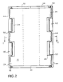
- each ofthe attachment segments 42 ofthe cover is received in a respective recessed section 28 of the housing 12, and likewise, each of the attachment portions 24 of the housing is received in a respective open section 44 of the cover.
- the edges of the cover side panels and the housing side walls are flush with each other when the cover and housing are assembled, as shown in Fig. 2.
- Attachment rod 50 is made of a material such as steel or a hard plastic, for example, nylon. Rod 50 extends continuously through the portions 24 and segments 42 to form a hinge along each side of the assembly. Attachment rod 50 has a first headed end 52. After insertion of the rod, a second headed end 54 can be crimped, for example, the rod may be heated and head 54 attached thereto, to keep the rod from sliding from the assembly.
- the rod can have a diameter within the range, for example, of and about 1/16 to 1/8 of an inch.
- grooves 25 and 45 can have a diameter in the range, of and about 1/16 to 1/8 of an inch, as well.
- Grooves 25 of housing 12 have a slightly loose fit with rod 50.
- grooves 45 of cover 14 have a tighter fit with rod 50, to provide a more controlled rotation upon opening of the cover door panels.
- cover 14 and housing 12 are further joined by a pair of end plates (not shown), as is known in the prior art.
- Housing 12 includes end plate mounting grooves 15, see Fig. 3. With the hinged attachment ofthe present invention, the end plates cover 14 and further control the opening thereof.
- the cover is injection molded in a single piece.
- the housing is extruded from a length of material, such as aluminum.
- the sidewalls 18, 20, the inflator housing 16 and the base portion 22 can be formed in a single step.
- the recessed sections 28 can be cut out along the free edge of the sidewalls.
- Each of the attachment segments 42 of the doors is received within a respective recessed section 28 ofthe housing and each ofthe attachment portions 24 of the housing is received within a respective open section 44 of the cover.
- the grooves 45 of the attachment segments 42 and the grooves 25 of the attachment portions 24 form a channel 48 between each of the housing sidewalls 18, 20 and the cover doors 32, 34.
- the attachment rod 50 can then be inserted through each channel 48 to form a direct hinged connection between the sidewalls of the housing and the doors of the cover.
- one end 52 is headed. After insertion, the second end 54 can be crimped so that the rod does not slide out of the channels.
- the grooves 24, 25 may be in the form of longitudinally open grooves as indicated at 25 on the housing, provided their walls extend sufficiently far around the rod to hold it securely.
- the attachment segments or portions 24, 42 may be in tubular form with axial bores, as indicated at 45 on the cover.
Landscapes
- Engineering & Computer Science (AREA)
- Mechanical Engineering (AREA)
- Air Bags (AREA)
Applications Claiming Priority (2)
| Application Number | Priority Date | Filing Date | Title |
|---|---|---|---|
| US658330 | 1996-06-05 | ||
| US08/658,330 US5722684A (en) | 1996-06-05 | 1996-06-05 | Hinged module cover |
Publications (2)
| Publication Number | Publication Date |
|---|---|
| EP0811532A2 true EP0811532A2 (fr) | 1997-12-10 |
| EP0811532A3 EP0811532A3 (fr) | 1998-09-09 |
Family
ID=24640798
Family Applications (1)
| Application Number | Title | Priority Date | Filing Date |
|---|---|---|---|
| EP97303868A Withdrawn EP0811532A3 (fr) | 1996-06-05 | 1997-06-05 | Couvercle pivotant pour module |
Country Status (3)
| Country | Link |
|---|---|
| US (1) | US5722684A (fr) |
| EP (1) | EP0811532A3 (fr) |
| JP (1) | JP3051225U (fr) |
Cited By (2)
| Publication number | Priority date | Publication date | Assignee | Title |
|---|---|---|---|---|
| EP0921044A3 (fr) * | 1997-12-08 | 2000-09-27 | TRW Occupant Restraint Systems GmbH & Co. KG | Module de coussin gonflable pour système de retenue de passager d'un véhicule |
| GB2391520A (en) * | 2002-08-06 | 2004-02-11 | Autoliv Dev | Cover for an air-bag |
Families Citing this family (8)
| Publication number | Priority date | Publication date | Assignee | Title |
|---|---|---|---|---|
| US5915724A (en) * | 1997-12-03 | 1999-06-29 | Chrysler Corporation | Airbag cover assembly with integrated hinge |
| US6206408B1 (en) * | 1999-01-25 | 2001-03-27 | Autoliv Asp, Inc. | Air bag module emergency venting system |
| US6581958B2 (en) | 2001-04-17 | 2003-06-24 | Autoliv Asp, Inc. | Energy managed airbag cover |
| US6834883B2 (en) * | 2001-05-23 | 2004-12-28 | Delphi Technologies, Inc. | Air bag housing and method of making |
| US7441799B2 (en) * | 2003-12-08 | 2008-10-28 | Autoliv Asp, Inc. | Non-circular steering wheel assembly and airbag module |
| US7152898B2 (en) * | 2005-01-06 | 2006-12-26 | Lear Corporation | System and method for reducing vehicle noise |
| US10899304B2 (en) * | 2018-05-18 | 2021-01-26 | Toyoda Gosei Co., Ltd. | Knee airbag assembly |
| EP3632752A1 (fr) * | 2018-10-05 | 2020-04-08 | Key Safety Systems, Inc. | Ensemble de module airbag conducteur et de volant de direction |
Family Cites Families (18)
| Publication number | Priority date | Publication date | Assignee | Title |
|---|---|---|---|---|
| US3756617A (en) * | 1969-09-15 | 1973-09-04 | Eaton Corp | Safety apparatus |
| US3708179A (en) * | 1970-08-07 | 1973-01-02 | Mccord Corp | Door assembly |
| US3643971A (en) * | 1970-08-11 | 1972-02-22 | Allied Chem | Self-inflating impact-absorbing bag for vehicles |
| US4941678A (en) * | 1989-06-29 | 1990-07-17 | Morton Thiokol, Inc. | Lightweight reaction can for passenger inflators |
| GB9112063D0 (en) * | 1991-06-05 | 1991-07-24 | Jaguar Cars | Improvements in and relating to air bag restraint systems |
| US5407226A (en) * | 1992-02-24 | 1995-04-18 | Morton International, Inc. | Inflatable restraint system reaction canister |
| JPH05246293A (ja) * | 1992-03-10 | 1993-09-24 | Takata Kk | 助手席用エアバッグ装置 |
| US5288103A (en) * | 1992-09-28 | 1994-02-22 | Davidson Textron Inc. | Airbag cover and apparatus for producing an invisible tear seam therein |
| JP2758539B2 (ja) * | 1992-09-29 | 1998-05-28 | 日本プラスト株式会社 | エアバッグカバー |
| WO1994025313A1 (fr) * | 1993-04-30 | 1994-11-10 | Alliedsignal Inc. | Module sac gonflable a boitier extrude |
| US5393089A (en) * | 1993-09-01 | 1995-02-28 | Chrysler Corporation | Vehicle air bag cover |
| US5470097A (en) * | 1993-09-03 | 1995-11-28 | Morton International, Inc. | Closure for air bag installation |
| US5411288A (en) * | 1993-11-03 | 1995-05-02 | Trw Vehicle Safety Systems Inc. | Air bag module door assembly |
| US5398960A (en) * | 1994-02-01 | 1995-03-21 | Morton International, Inc. | Airbag module doors having slip-in and snap-in tether attachments |
| US5431433A (en) * | 1994-05-02 | 1995-07-11 | Morton International, Inc. | Fastenerless tethered deployment door for passenger-side airbag module |
| US5474325A (en) * | 1994-09-29 | 1995-12-12 | Morton International, Inc. | Slide-in protective cover for passenger airbag module |
| US5511819A (en) * | 1995-03-27 | 1996-04-30 | Morton International, Inc. | Fastenerless automotive passenger airbag module endcap |
| FR2744968B1 (fr) * | 1996-02-15 | 1998-05-15 | Ecia Equip Composants Ind Auto | Ensemble de module a sac gonflable, notamment pour vehicule automobile |
-
1996
- 1996-06-05 US US08/658,330 patent/US5722684A/en not_active Expired - Fee Related
-
1997
- 1997-06-04 JP JP1997004703U patent/JP3051225U/ja not_active Expired - Fee Related
- 1997-06-05 EP EP97303868A patent/EP0811532A3/fr not_active Withdrawn
Cited By (4)
| Publication number | Priority date | Publication date | Assignee | Title |
|---|---|---|---|---|
| EP0921044A3 (fr) * | 1997-12-08 | 2000-09-27 | TRW Occupant Restraint Systems GmbH & Co. KG | Module de coussin gonflable pour système de retenue de passager d'un véhicule |
| US6161864A (en) * | 1997-12-08 | 2000-12-19 | Trw Occupant Restraint Systems Gmbh & Co. Kg | Gas bag module for a vehicle occupant restraint system |
| GB2391520A (en) * | 2002-08-06 | 2004-02-11 | Autoliv Dev | Cover for an air-bag |
| GB2391520B (en) * | 2002-08-06 | 2005-08-10 | Autoliv Dev | Improvements in or relating to a cover for an air bag |
Also Published As
| Publication number | Publication date |
|---|---|
| US5722684A (en) | 1998-03-03 |
| JP3051225U (ja) | 1998-08-21 |
| EP0811532A3 (fr) | 1998-09-09 |
Similar Documents
| Publication | Publication Date | Title |
|---|---|---|
| EP0695671B1 (fr) | Système d'air-bag avec sangle de retenue pour couvercle | |
| EP0629527B1 (fr) | Fermeture pour sac d'air | |
| US7293794B2 (en) | Cover attachment | |
| US5520410A (en) | Door locking mechanism for air bag module | |
| US5346249A (en) | Airbag cover hinge reinforcement for high performance inflator | |
| US5031930A (en) | Air bag system | |
| EP0669230B1 (fr) | Liaison multidirectionelle pour un couvercle d'un module de sac à air | |
| JP4093140B2 (ja) | 頭部保護エアバッグ装置 | |
| EP0695670B1 (fr) | Système de fixation frangible pour couvercles de déploiement de sacs gonflables | |
| US20040004343A1 (en) | Airbag module and cover arrangement | |
| KR19990063766A (ko) | 에어백 | |
| US20020195801A1 (en) | Air bag deployment chute and panel assembly | |
| WO1999051466A1 (fr) | Garniture de plafond de vehicule automobile | |
| US5474324A (en) | Tethered cover airbag system | |
| EP0623493B1 (fr) | Fermeture pour un système de retenue gonflable | |
| JP2000025554A (ja) | 車の安全装置 | |
| US20070080521A1 (en) | Motor vehicle part including an airbag safety device, and a method of assembling such a part | |
| US5722684A (en) | Hinged module cover | |
| US20070182131A1 (en) | Housing for an airbag device | |
| EP0710591B1 (fr) | Porte sans jointure pour module de coussin d'air | |
| EP0615888A1 (fr) | Couvercle pour sac gonflable | |
| JPH0538993A (ja) | サイドエアバツグの取付構造 | |
| US5971427A (en) | Side impact air bag clamshell-wrap around strap closure | |
| JPH0781512A (ja) | エアバッグ展開用開口のための閉鎖要素 | |
| EP1700754A1 (fr) | Coussin gonflable en forme de rideau |
Legal Events
| Date | Code | Title | Description |
|---|---|---|---|
| PUAI | Public reference made under article 153(3) epc to a published international application that has entered the european phase |
Free format text: ORIGINAL CODE: 0009012 |
|
| AK | Designated contracting states |
Kind code of ref document: A2 Designated state(s): AT BE CH DE DK ES FI FR GB GR IE IT LI LU MC NL PT SE |
|
| PUAL | Search report despatched |
Free format text: ORIGINAL CODE: 0009013 |
|
| AK | Designated contracting states |
Kind code of ref document: A3 Designated state(s): AT BE CH DE DK ES FI FR GB GR IE IT LI LU MC NL PT SE |
|
| PUAL | Search report despatched |
Free format text: ORIGINAL CODE: 0009013 |
|
| AKX | Designation fees paid | ||
| STAA | Information on the status of an ep patent application or granted ep patent |
Free format text: STATUS: THE APPLICATION IS DEEMED TO BE WITHDRAWN |
|
| 18D | Application deemed to be withdrawn |
Effective date: 19990512 |
|
| REG | Reference to a national code |
Ref country code: DE Ref legal event code: 8566 |