EP0812059B1 - Regelverfahren für eine Drehmaschine, Einrichtung zur Durchführung des Verfahrens und Anwendung der Einrichtung bei einer Drehmaschine - Google Patents
Regelverfahren für eine Drehmaschine, Einrichtung zur Durchführung des Verfahrens und Anwendung der Einrichtung bei einer Drehmaschine Download PDFInfo
- Publication number
- EP0812059B1 EP0812059B1 EP97401181A EP97401181A EP0812059B1 EP 0812059 B1 EP0812059 B1 EP 0812059B1 EP 97401181 A EP97401181 A EP 97401181A EP 97401181 A EP97401181 A EP 97401181A EP 0812059 B1 EP0812059 B1 EP 0812059B1
- Authority
- EP
- European Patent Office
- Prior art keywords
- computer
- vector
- stator
- phase voltage
- state
- Prior art date
- Legal status (The legal status is an assumption and is not a legal conclusion. Google has not performed a legal analysis and makes no representation as to the accuracy of the status listed.)
- Expired - Lifetime
Links
- 238000000034 method Methods 0.000 title claims abstract description 45
- 230000008569 process Effects 0.000 title description 13
- 239000013598 vector Substances 0.000 claims abstract description 102
- 230000004907 flux Effects 0.000 claims abstract description 71
- 230000001052 transient effect Effects 0.000 claims description 26
- 238000011217 control strategy Methods 0.000 claims description 19
- 125000004122 cyclic group Chemical group 0.000 claims description 9
- 238000005070 sampling Methods 0.000 claims description 7
- 230000001105 regulatory effect Effects 0.000 claims description 4
- 230000010355 oscillation Effects 0.000 claims description 2
- PXFBZOLANLWPMH-UHFFFAOYSA-N 16-Epiaffinine Natural products C1C(C2=CC=CC=C2N2)=C2C(=O)CC2C(=CC)CN(C)C1C2CO PXFBZOLANLWPMH-UHFFFAOYSA-N 0.000 claims 1
- 230000001419 dependent effect Effects 0.000 claims 1
- 230000004044 response Effects 0.000 description 8
- 230000008901 benefit Effects 0.000 description 5
- 230000009467 reduction Effects 0.000 description 3
- 230000001276 controlling effect Effects 0.000 description 2
- 230000006866 deterioration Effects 0.000 description 2
- 238000012423 maintenance Methods 0.000 description 2
- 230000000739 chaotic effect Effects 0.000 description 1
- 238000010276 construction Methods 0.000 description 1
- 230000037213 diet Effects 0.000 description 1
- 235000005911 diet Nutrition 0.000 description 1
- 230000001939 inductive effect Effects 0.000 description 1
- 238000009434 installation Methods 0.000 description 1
- 230000002427 irreversible effect Effects 0.000 description 1
- 230000007257 malfunction Effects 0.000 description 1
Images



Classifications
-
- H—ELECTRICITY
- H02—GENERATION; CONVERSION OR DISTRIBUTION OF ELECTRIC POWER
- H02P—CONTROL OR REGULATION OF ELECTRIC MOTORS, ELECTRIC GENERATORS OR DYNAMO-ELECTRIC CONVERTERS; CONTROLLING TRANSFORMERS, REACTORS OR CHOKE COILS
- H02P23/00—Arrangements or methods for the control of AC motors characterised by a control method other than vector control
- H02P23/30—Direct torque control [DTC] or field acceleration method [FAM]
-
- H—ELECTRICITY
- H02—GENERATION; CONVERSION OR DISTRIBUTION OF ELECTRIC POWER
- H02P—CONTROL OR REGULATION OF ELECTRIC MOTORS, ELECTRIC GENERATORS OR DYNAMO-ELECTRIC CONVERTERS; CONTROLLING TRANSFORMERS, REACTORS OR CHOKE COILS
- H02P21/00—Arrangements or methods for the control of electric machines by vector control, e.g. by control of field orientation
- H02P21/24—Vector control not involving the use of rotor position or rotor speed sensors
- H02P21/28—Stator flux based control
- H02P21/30—Direct torque control [DTC] or field acceleration method [FAM]
Definitions
- the invention relates to a process for controlling and controlling a machine. rotating, a servo device intended to implement said method, and a rotating machine provided with such a device. More specifically the present invention relates to a torque control process and a stator flow of a machine rotating.
- This method involves vector modeling of the machine and the voltage inverter.
- the electromagnetic torque is a function of the angle existing between the rotating rotor flux vector and the stator flux rotating vector and the modules of these flux vectors.
- the stator voltage vector V s is delivered by a three-phase voltage inverter each phase comprising a two-state switch (SP2LL): Single Pole 2 Logic Levels / single pole with 2 logic levels). Therefore, the stator voltage vector V s can take 8 states V 1 ... V 8 (2 3 ), including two V 1 , V 8 of zero amplitude (zero states) in the fixed stator frame ( ⁇ , ⁇ ), depending on the combination of the three SP2LLs of the inverter.
- SP2LL two-state switch
- Fig. 1 a system called DTC (Direct Torque Control) based, in the stator frame ( ⁇ , ⁇ ), on the maintenance of the module
- DTC Direct Torque Control
- the control of the stator flux vector ⁇ S is ensured by means of a finite table.
- the finished table below and figure 1 illustrates this method.
- ⁇ S is in the area N 6 and its end follows the state V 2 of the stator phase voltage vector V s .
- the state V 2 is a state which makes grow
- the process will switch to V 3 as soon as
- the device stops the rotation of the stator flow (zero state) and the rotor flow catches up with the stator flow thereby reducing the angle and therefore the torque.
- the flow rotor also rotates at low speed, which significantly affects the torque response dynamics.
- One of the aims of the present invention is to propose a method where, the control quantities also being the electromagnetic torque and the stator flux, whatever the situation of the rotating machine at a given time, the state of the optimal stator phase voltage vector V s , among all possible states, to best respond to the desired control strategy.
- the invention relates to a method of regulating a rotating machine with n phases supplied with alternating current via a voltage inverter, comprising n SPmLL defining m "states V i (i ⁇ ⁇ 1, .., m n ) of the stator phase voltage vector V s , said machine being controlled by an electromagnetic couple T em and by a stator flux ⁇ s to an electromagnetic couple T emref and by a stator flux ⁇ sref by a control system comprising a set of sensors whose sensed values are transmitted to an observer, the outputs of the observer being injected into a computer, said computer outputting control signals intended to control the SPmLLs of the voltage inverter.
- n and / or m have high values this generates many possible states.
- the invention then has for other advantage that when one of the SPmLL is accidentally locked in a position that is not optimal for a given configuration, the process will continue to choose the state the best possible among the remaining possible states for get closer to the instructions. The dynamic performance of control are affected, but the risk of discrepancies or peak torque are minimized.
- the computer in the process initialization step we construct, in the computer, a cyclic path of circulation from point A around point A ref in the plan element, an average switching frequency for the inverter is entered in the computer, the computer divides the plane element into switching zones Z i adapted to the cyclic path, the computer builds a switching table in which for each zone Z i it matches the future optimal state V f of the stator phase voltage vector V S as a function of the current states V a and past V p of the stator phase voltage vector V S to follow the cyclic circulation path in said zone Z i ; and in that, under steady state, and at each sampling, the computer calculates the sizes of the switching zones Z i as a function of the instantaneous configuration of the machine, so as to respect the chosen average cutting frequency, the computer chooses as control vector C the optimal future state V f of the stator phase voltage vector V s , from the switching table, as a function of the zone Z i where point A is located, and of the current states V a and
- Control of the average switching frequency of the inverter is an advantage to limit significantly the switching losses in SPmLL and therefore extend their lifespan.
- the invention also relates to a servo system implementing the method described above.
- the invention finally relates to a rotating machine including such a servo system.
- Figure 1 is a schematic representation in the fixed stator plan of the method of the prior art.
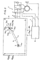
- Figure 2 is a schematic representation of the method according to the invention for a transient regime.
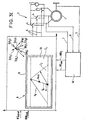
- Figures 3 to 3E are representations schematics of the method according to the invention for a diet established, from a given example cycle.
- the invention relates to a method for regulating a rotary machine 1 to n Phases supplied with alternating current by means of a voltage inverter 3 comprising n switches with m positions 4 (hereinafter SPmLL: Single Pole m Logic Levels / single pole at m logic levels) defining m n states V i (i ⁇ ⁇ 1, .., m n ⁇ ) of the stator phase voltage vector V S , said machine 1 being slaved to an electromagnetic couple T emref and to a stator flow ⁇ Setpoint ref.
- SPmLL Single Pole m Logic Levels / single pole at m logic levels
- the control system of the machine comprises a set of sensors whose sensed values 7, 8, 9 are transmitted to an observer 10.
- the outputs of the observer 10 are values representative of the electromechanical couple T em and of the stator flux ⁇ S of the rotating machine. There are many more or less sophisticated sensors and observers 10.
- the values representative of the electromagnetic torque T em and of the stator flux ⁇ S are injected into the computer 13 implementing the method according to the invention.
- This computer 13 also receives as inputs the values representative of the setpoints T emref , ⁇ Sref of the electromechanical torque and the stator flux.
- the computer 13 outputs control signals 6 intended to control the SPmLLs 4 of the voltage inverter 3.
- the invention relates more precisely to the steps of process taking place in the computer 13.
- an output plane P is constructed in the computer 13, one of the axes of which is representative of the electromagnetic torque and the other x axis is representative of the stator flux, it defines a point a ref representing instructions torque and stator flux in said plane and a point a representing the instantaneous configuration of the machine, is defined around the point a ref part of plane 5 ⁇ ⁇ x, ⁇ ⁇ y inside which one is in steady state, and outside which one is in transient state. Therefore plan P is divided into two parts, each representing one of the plans.
- the method chooses from the set of possible states V i (i ⁇ ⁇ 1, .., m n ⁇ ) of the stator phase voltage vector V s that which offers the greatest speed of variation from point A in a direction close to the ideal direction (AA ref ) of approach.
- a state model of the rotating machine is introduced into the computer 13 in which the output vector S is a vector of the output plane P and the control vector C is the vector phase voltage V s ; and under transient conditions, at each sampling, the computer 13 calculates the vector (AA ref ), the computer 13 calculates the directional derivative S ⁇ of the output vector S for each of the possible states V i of the phase voltage vector V s , the computer 13 calculates the scalar product of each of the directional derivatives S ⁇ (V i ) of the output vector S with the vector (AA ref ), the computer chooses as control vector C the state V i of the phase voltage vector V s associated with the largest of the scalar products calculated.
- FIG. 2 represents the operation of the process in transient regime.
- the dotted line 15 represents the ideal path for A to join A ref as quickly as possible.
- the vector (AA ref ) is recalculated as well as the optimal state. This can result, for example, in a trajectory as represented by curve 14.
- n and / or m many states other advantage than when one of the SPmLL is accidentally stuck in a position that is not optimal for a given configuration, the process will continue to choose the best possible state among possible remaining states to get closer to the instructions. Dynamic control performance is affected, but the risks of divergences or peak of torque are deleted.
- a cyclic path 15 of circulation from point A around point A ref in the plane element 5 is constructed in the computer 13, an average switching frequency is entered into the computer for the inverter 3, the computer divides the plane element 5 into switching zones Z i adapted to the cyclic path 15, the computer builds a switching table in which for each zone Z i it matches the future optimal state V f of the stator phase voltage vector V s as a function of the current states V a and past V p of the stator phase voltage vector V s to follow the cyclic path 15 of circulation in said zone Z i ; and in that, under steady state, and at each sampling, the computer 13 calculates the sizes of the switching zones Z i as a function of the instantaneous configuration of the machine, so as to respect the chosen average cutting frequency the computer chooses as control vector C the optimal future state V f of the stator phase voltage vector V s , from the switching table, as a function of the zone Z i where
- Figure 3 shows the cycle 15 chosen.
- Figures 3A to 3E as well as the table above shows an example of circulation of point A according to the cycle 15 chosen.
- the positioning and dimensioning of the zones Z i have an influence on the average switching frequency of the inverter and vice versa.
- the average frequency of switching of the inverter is taken into account during the construction of the zones Z i .
- Control of the average switching frequency of the inverter is an advantage to limit significantly the risks of deterioration of SPmLL and extend their service life.
- point A is either in zone Z 2 or in zone Z 4 , the current state is V 3 , the past state is V 2 .
- Point A may, in the future, pass into zone Z 5 , Z 1 , or Z 3 .
- the future state will remain the current state V 3 , if point A passes through one of the zones Z 5 , Z 1 , or Z 3 , the future state is V 1 .
- FIGS 3B to 3E can be explained in the same way way using the switching table.
- the y-axis directly represents the electromagnetic torque
- the x-axis represents the square of the stator flux.
- the points of the plane P have the coordinates: ( ⁇ S 2 / ⁇ o 2 , ( ⁇ -1) T em / T o ) where ⁇ is a weighting coefficient whose value is set by the user of the rotating machine. This weighting coefficient makes it possible to give a more or less significant weight to one of the outputs compared to the other.
- the invention also relates to a servo system implementing the method described above.
- the invention finally relates to a rotating machine including such a servo system.
Landscapes
- Engineering & Computer Science (AREA)
- Power Engineering (AREA)
- Control Of Ac Motors In General (AREA)
- Control Of Electric Motors In General (AREA)
- Extrusion Moulding Of Plastics Or The Like (AREA)
- Turning (AREA)
- Control Of Multiple Motors (AREA)
- Control Of Velocity Or Acceleration (AREA)
- Selective Calling Equipment (AREA)
- Control Of Eletrric Generators (AREA)
- Coating Apparatus (AREA)
- Threshing Machine Elements (AREA)
Claims (7)
- Verfahren zur Regelung einer n-phasigen Drehmaschine (1), welche mit Wechselstrom mittels eines Spannungswechselrichters (3) versorgt wird, welcher n SPmLL (4) umfasst, die mn Zustände Vi (I ∈ {1,...,mn }) des Statorphasenspannungsvektors VS definieren, welche Maschine in dem elektromagnetischen Moment Tem und dem Statorfluss Θ s mit einem elektromagnetischen Moment Temref und mit einem Statorfluss Θ Sref durch ein Regelsystem geregelt wird, welches einen Satz von Aufnehmern umfasst, deren erfassten Werte (7, 8, 9) an einen Beobachter (10) übertragen werden, die Ausgänge des Beobachters (10) in einen Rechner (13) eingegeben werden, welcher Rechner (13) am Ausgang Steuersignale (6) abgibt, welche bestimmt sind die SPmLL (4) des Spannungswechselrichters (3) zu steuern,
wobei in einer Regelungsstrategie für einen Übergangsbereich, in welchem sich das elektromagnetische Moment Tem und/oder der Statorfluss Θ s , jeweils vom elektromagnetischen Sollmoment Temref und/oder Sollstatorfluss Θ Sref entfernen, der Rechner (13) unter den möglichen Zuständen Vi des Phasenspannungsvektors Vs denjenigen auswählt, der optimal ist um das Moment Tem und den Statorfluss Θ S zum Sollmoment Temref and Sollstatorfluss Θ Sref zu bringen, und gibt Regelsignale (6) ab, um die SPmLL (4) entsprechend dem gewählten Zustand des Phasenspannungsvektors Vs zu regeln,
und dadurch gekennzeichnet ist, dass in einem Initialisierungsschritt des Verfahrens in dem Rechner (13) eine virtuelle Ausgangsfläche P konstruiert wird, in welcher eine (y) der Achsen für das elektromagnetische Moment und die andere Achse (x) für den Statorfluss steht. die Sollwerte des Moments und des Statorflusses durch einen Punkt Aref und das momentane Moment und der momentane Statorfluss durch einen Punkt A dargestellt werden, ein Flächenelement (5) (±Δx, ±Δy) um den Punkt Aref definiert wird,
und der Rechner (13) die Strategie der Regelung im Bestimmungsbereich verwendet. wenn sich der Punkt A innerhalb des Flächenelements (5) befindet, und die Strategie der Regelung im Übergangsbereich verwendet, wenn sich der Punkt A außerhalb des Flächenelements (5) befindet, wobei die Strategie der Regelung im Übergangsbereich die folgenden Schritte umfasst:man bringt in den Rechner (13) ein Zustandsmodell der Drehmaschine ein, in welchem der Ausgangsvektor S ein Vektor der Ausgangsfläche P und der Regelungsvektor C der Phasenspannungsvektor Vs ist; undim Übergangsbereich berechnet der Rechner (13) bei jeder Stichprobe den Vektor (A-Aref), der Rechner (13) berechnet die Richtungsableitung S ˙ des Vektors von S für jeden der möglichen Zustände Vi des Phasenspannungsvektors Vs,der Rechner (13) berechnet das Skalarprodukt jeder der Richtungsableitungen S ˙(V i ) des Ausgangsvektors S mit dem Vektor (A-Aref),der Rechner wählt als Regelungsvektor C den Zustand Vi des Phasenspannungsvektors Vs, der am besten zu den berechneten Skalarprodukten passt. - Verfahren zur Regelung einer Drehmaschine nach Anspruch 1, wobei bei einer Strategie der Regelung für einen Bestimmungsbereich, in welchem der Moment Tem und der Statorfluss Θ S jeweils in einem Intervall ±ΔTem um Temref und in einem Intervall ±ΔΘ S um Θ Sref enthalten sind,
der Rechner (13) aus den möglichen Zuständen Vi des Statorphasenspannungsvektors VS denjenigen auswählt, der für eine voreingestellte mittlere Teilungsfrequenz des Wechselrichters (3) optimal ist um die jeweiligen Schwingungsamplituden des Moments Tem und des Statorflusses Θ S um das Sollmoment Temref und den Sollstatorfluss Θ Sref zu minimalisieren, und/oder um ein Frequenzmaß für das Moment Tem einzuhalten,
der Rechner (13) Steuersignale (6) abgibt um die SPmLL (4) entsprechend dem gewählten Zustand des Statorphasenspannungsvektors VS zu regeln. - Verfahren nach einem der Ansprüche 1 oder 2, bei welchem ferner in dem Initialisierungsschritt des Verfahrens
in dem Rechner (13) ein zyklischer Weg (15) für den Umlauf des Punktes A um den Punkt Aref in dem Flächenelement (5) konstruiert wird,
der Rechner das Flächenelement (5) in Vertauschungszonen Zi einteilt, welche dem zyklischen Weg (15) angepasst sind,
in den Rechner eine mittlere Teilungsfrequenz für den Wechselrichter (3) eingegeben wind,
der Rechner eine Vertauschungstabelle konstruiert, in welcher für jede Zone Zi der optimale zukünftige Zustand Vf des Statorphasenspannungsvektors Vs einer Funktion der aktuellen Zustände Va und der vergangenen Zustände Vp des Statorphasenspannungsvektor Vs entspricht um dem zyklischen Umlaufweg (15) in der Zone Zi zu folgen, und wobei
im Bestimmungsbereich und bei jeder Stichprobe der Rechner (13) die Größen der Vertauschungszonen Zi als Funktion der Momentankonfiguration der Maschine berechnet, derart, dass die mittlere Frequenz der gewählten Teilung berücksichtigt wird,
der Rechner als Regelungsvektor C den zukünftigen optimalen Zustand Vf des Statorphasenspannungsvektors Vs anhand der Vertauschungstabelle als Funktion der Zone Zi, worin sich der Punkt A befindet, und der aktuellen Zustände Va und der vergangenen Zustände Vp des Statorphasenspannungsvektors Vs wählt. - Verfahren nach einem der Ansprüche 1 bis 3, bei welchem das Modell der Drehmaschine ein nichtlineares Modell, genauer eine Regelung vom Typ:
die Richtungsableitung S ˙ des Ausgangsvektors S ist: - Verfahren nach einem der Ansprüche 1 bis 4, bei welchem das Flächenelement (5) ein Hystereseband mit einer unteren Grenze (12) und einer oberen Grenze (11) umfasst, derart, dass:das Wechseln der Regelungsstrategie im Übergangsbereich zur Regelungsstrategie im Bestimmungsbereich dann erfolgt, wenn der Punkt A die untere Grenze (12) des Hysteresebands überschritten hat; unddas Wechseln der Regelungsstrategie im Bestimmungsbereich zur Regelungsstrategie im Übergangsbereich dann erfolgt, wenn der Punkt A die obere Grenze (11) des Hysteresebands überschritten hat.
- Regeleinrichtung einer n-phasigen Drehmaschine (1), welche mit Weehselstrom mittels eines Spannungswechselrichters (3) versorgt wird, welcher n SPmLL (4) umfasst, die mn Zustände Vi (I ∈ {1,...,mn }) des Statorphasenspannungsvektors VS definieren, welche Maschine in dem elektromagnetischen Moment Tem und dem Statorfluss Θ S mit einem elektromagnetischen Moment Temref und mit einem Statorfluss Θ Sref durch ein Regelsystem geregelt wird, welches einen Satz von Aufnehmern umfasst, deren erfassten Werte (7, 8, 9) an einen Beobachter (10) übertragen werden, die Ausgänge des Beobachters (10) in einen Rechner (13) eingegeben werden, welcher Rechner (13) am Ausgang Steuersignale (6) abgibt, welche bestimmt sind die SPmLL (4) des Spannungswechselrichters (3) zu steuern, dadurch gekennzeichnet ist, dass die Einrichtung das Verfahren nach einem der Ansprüche 1 bis 5 durchführt.
- Anwendung der Einrichtung nach Anspruch 6 auf eine n-phasige Drehmaschine, welche mit Wechselstrom mittels eines Spannungswechselrichters (3) versorgt wird, welcher n SPmLL (4) umfasst, die mn Zustände Vi (I ∈ {1,...,mn }) des Statorphasenspannungsvektors VS definieren, welche Maschine in dem elektromagnetischen Moment Tem und dem Statorfluss Θ S mit einem elektromagnetischen Moment Temref und mit einem Statorfluss Θ Sref durch ein Regelsystem geregelt wird, welches einen Satz von Aufnehmern umfasst, deren erfassten Werte (7, 8, 9) an einen Beobachter (10) übertragen werden, die Ausgänge des Beobachters (10) in einen Rechner (13) eingegeben werden, welcher Rechner (13) am Ausgang Steuersignale (6) abgibt, welche bestimmt sind die SPmLL (4) des Spannungswechselrichters (3) zu steuern, wobei die Regeleinrichtung Anspruch 6 entspricht.
Applications Claiming Priority (2)
| Application Number | Priority Date | Filing Date | Title |
|---|---|---|---|
| FR9607015 | 1996-06-06 | ||
| FR9607015A FR2749717B1 (fr) | 1996-06-06 | 1996-06-06 | Procede de controle commande d'une machine tournante, systeme d'asservissement pour mettre en oeuvre ledit procede, machine tournante pourvue d'un tel systeme |
Publications (3)
| Publication Number | Publication Date |
|---|---|
| EP0812059A1 EP0812059A1 (de) | 1997-12-10 |
| EP0812059B1 true EP0812059B1 (de) | 2003-02-26 |
| EP0812059B8 EP0812059B8 (de) | 2003-05-21 |
Family
ID=9492782
Family Applications (1)
| Application Number | Title | Priority Date | Filing Date |
|---|---|---|---|
| EP97401181A Expired - Lifetime EP0812059B8 (de) | 1996-06-06 | 1997-05-29 | Regelverfahren für eine Drehmaschine, Einrichtung zur Durchführung des Verfahrens und Anwendung der Einrichtung bei einer Drehmaschine |
Country Status (15)
| Country | Link |
|---|---|
| US (1) | US5907228A (de) |
| EP (1) | EP0812059B8 (de) |
| JP (1) | JPH1066400A (de) |
| KR (1) | KR980006793A (de) |
| CN (1) | CN1097756C (de) |
| AT (1) | ATE233448T1 (de) |
| AU (1) | AU714400B2 (de) |
| BR (1) | BR9703478A (de) |
| CA (1) | CA2208008A1 (de) |
| CZ (1) | CZ172897A3 (de) |
| DE (1) | DE69719240T2 (de) |
| FR (1) | FR2749717B1 (de) |
| HU (1) | HUP9701008A3 (de) |
| PL (1) | PL320397A1 (de) |
| SK (1) | SK71597A3 (de) |
Families Citing this family (14)
| Publication number | Priority date | Publication date | Assignee | Title |
|---|---|---|---|---|
| FR2791488B1 (fr) * | 1999-03-25 | 2002-09-20 | Schneider Electric Sa | Systeme de controle d'un onduleur de tension |
| FI112299B (fi) | 2000-12-22 | 2003-11-14 | Abb Industry Oy | Menetelmä taajuusmuuttajan yhteydessä |
| WO2003073185A2 (en) * | 2002-02-28 | 2003-09-04 | Zetacon Corporation | Predictive control system and method |
| US7121269B2 (en) * | 2003-04-16 | 2006-10-17 | Michael North | Hot-start solenoid valve |
| US7274865B2 (en) * | 2003-09-04 | 2007-09-25 | Patricio Lagos Lehuede | General purpose 100% solid state drive for direct current rotary machines |
| EP1711998B1 (de) * | 2004-02-05 | 2007-08-29 | Honeywell International, Inc. | Motorsteuerung und antrieb für ansprechzeitverbesserung einer electrischen anwendung |
| DE502004009328D1 (de) | 2004-12-10 | 2009-05-20 | Abb Research Ltd | Verfahren zum Betrieb einer rotierenden elektrischen Maschine |
| EP2034606B1 (de) * | 2007-09-10 | 2015-03-11 | ABB Research Ltd. | Verfahren zum Betrieb einer rotierenden elektrischen Maschine |
| KR100933393B1 (ko) * | 2007-10-31 | 2009-12-22 | 울산대학교 산학협력단 | 유도 전동기의 직접 토크 제어 장치 및 방법 |
| DE102008002505A1 (de) * | 2008-06-18 | 2009-12-24 | Robert Bosch Gmbh | Verfahren zum Betrieb einer elektrischen Antriebsvorrichtung und Steuergerät |
| JP5391697B2 (ja) * | 2009-01-16 | 2014-01-15 | 株式会社デンソー | 回転機の制御装置及び制御システム |
| JP5391696B2 (ja) * | 2009-01-16 | 2014-01-15 | 株式会社デンソー | 回転機の制御装置及び制御システム |
| ES2395509T3 (es) * | 2010-01-22 | 2013-02-13 | Abb Research Ltd. | Control de una máquina eléctrica giratoria |
| CN119156766A (zh) * | 2022-01-28 | 2024-12-17 | 塔乌电机股份有限公司 | 使用分段仿射模型的电机控制 |
Family Cites Families (4)
| Publication number | Priority date | Publication date | Assignee | Title |
|---|---|---|---|---|
| US4707651A (en) * | 1986-07-22 | 1987-11-17 | Westinghouse Electric Corp. | Voltage-controlled field-oriented induction motor control system |
| US5585709A (en) * | 1993-12-22 | 1996-12-17 | Wisconsin Alumni Research Foundation | Method and apparatus for transducerless position and velocity estimation in drives for AC machines |
| US5708346A (en) * | 1994-01-10 | 1998-01-13 | Sulzer Electronics Ag | Method and control apparatus for controlling an AC-machine |
| US5502360A (en) * | 1995-03-10 | 1996-03-26 | Allen-Bradley Company, Inc. | Stator resistance detector for use in electric motor controllers |
-
1996
- 1996-06-06 FR FR9607015A patent/FR2749717B1/fr not_active Expired - Fee Related
-
1997
- 1997-05-29 DE DE69719240T patent/DE69719240T2/de not_active Expired - Fee Related
- 1997-05-29 AT AT97401181T patent/ATE233448T1/de not_active IP Right Cessation
- 1997-05-29 EP EP97401181A patent/EP0812059B8/de not_active Expired - Lifetime
- 1997-06-04 CZ CZ971728A patent/CZ172897A3/cs unknown
- 1997-06-05 HU HU9701008A patent/HUP9701008A3/hu unknown
- 1997-06-05 AU AU24703/97A patent/AU714400B2/en not_active Ceased
- 1997-06-05 SK SK715-97A patent/SK71597A3/sk unknown
- 1997-06-05 PL PL97320397A patent/PL320397A1/xx unknown
- 1997-06-05 US US08/870,413 patent/US5907228A/en not_active Expired - Fee Related
- 1997-06-05 CA CA002208008A patent/CA2208008A1/fr not_active Abandoned
- 1997-06-06 JP JP9149099A patent/JPH1066400A/ja active Pending
- 1997-06-06 CN CN97114854A patent/CN1097756C/zh not_active Expired - Fee Related
- 1997-06-06 BR BR9703478A patent/BR9703478A/pt active Search and Examination
- 1997-06-07 KR KR1019970023530A patent/KR980006793A/ko not_active Withdrawn
Also Published As
| Publication number | Publication date |
|---|---|
| US5907228A (en) | 1999-05-25 |
| JPH1066400A (ja) | 1998-03-06 |
| BR9703478A (pt) | 1998-08-04 |
| SK71597A3 (en) | 1998-01-14 |
| PL320397A1 (en) | 1997-12-08 |
| AU714400B2 (en) | 2000-01-06 |
| HUP9701008A3 (en) | 2000-03-28 |
| FR2749717A1 (fr) | 1997-12-12 |
| EP0812059B8 (de) | 2003-05-21 |
| AU2470397A (en) | 1997-12-11 |
| EP0812059A1 (de) | 1997-12-10 |
| CZ172897A3 (en) | 1997-12-17 |
| DE69719240T2 (de) | 2003-12-04 |
| ATE233448T1 (de) | 2003-03-15 |
| FR2749717B1 (fr) | 1998-07-31 |
| HU9701008D0 (en) | 1997-07-28 |
| CA2208008A1 (fr) | 1997-12-06 |
| KR980006793A (ko) | 1998-03-30 |
| HUP9701008A2 (hu) | 1998-01-28 |
| DE69719240D1 (de) | 2003-04-03 |
| CN1097756C (zh) | 2003-01-01 |
| CN1177758A (zh) | 1998-04-01 |
Similar Documents
| Publication | Publication Date | Title |
|---|---|---|
| EP2246973B1 (de) | Verfahren zur Positionsbestimmung des Flussvektors eines Motors | |
| EP0579948B1 (de) | Steuersystem für einen Asynchronmotor | |
| EP0812059A1 (de) | Regelverfahren für eine Drehmaschine, Servosystem zur Durchführung des Verfahrens und Drehmaschine mit einem solchen System | |
| EP0770430B1 (de) | Verfahren und Vorrichtung zur Ansteuerung von Leistungs-Ultraschallgebern | |
| FR2681483A1 (fr) | Circuit de commande de moteur a induction. | |
| FR2911698A1 (fr) | Dispositif de commande d'actionneur electromecanique. | |
| FR2681194A1 (fr) | Procede pour determiner la vitesse angulaire de glissement d'un moteur a induction. | |
| WO2013178906A1 (fr) | Procede de commande du couple electromagnetique d'une machine synchrone a haute vitesse | |
| FR2867324A1 (fr) | Dispositif de commande de machine synchrone a champs enroules | |
| EP4216424B1 (de) | Verfahren und system zur steuerung einer von einem wechselrichter gesteuerten elektrischen maschine mit mehreren schaltarmen mit zwei servoverfahren | |
| EP3166220B1 (de) | Vorrichtung zur dynamischen begrenzung, und verfahren zur dynamischen begrenzung durch eine solche vorrichtung | |
| EP0858155A1 (de) | Verfahren zur Steuerung einer rotierenden Maschine, Steuerungsystem zur Durchführung dieses Verfahrens und rotierende Maschine mit einem solchen System | |
| EP3888240B1 (de) | Steuerungmethode und zugehöriges steuerungsystem | |
| EP1233506A1 (de) | Regelverfahren und Vorrichtung für eine rotierende elektrische Wechselstrommaschine, insbesondere Synchronmaschine | |
| EP1484835A2 (de) | Verfahren und System zum Steuern des augenblickligen elektromagnetischen Drehmoments, und Datenträger zum Durchführen des Verfahrens | |
| EP4416835B1 (de) | Verfahren zur schätzung der position und geschwindigkeit des rotors eines permanentmagnet-synchronmotors | |
| EP0702451A1 (de) | Steuervorrichtung eines Synchronmotors | |
| EP1686682B1 (de) | Verfahren und System zur Begrenzung des Ausgangsstroms für einen V/f Umrichter | |
| EP0469509B1 (de) | Verfahren und Vorrichtung zur Steuerung eines Asynchronmotors durch Regelung des magnetischen Induktionsflusses | |
| EP0388845A1 (de) | Vektorregelungssystem für elektrischen Induktionsmotor mit Kurzschlussläufer | |
| FR2974465A1 (fr) | Procede de detection d'une position angulaire d'un rotor de machine synchrone ; application a la mise en position et au maintien en position d'un rotor de machine synchrone, et a la commande d'un rotor de machine synchrone ; et dispositifs correspondants | |
| EP1703628B1 (de) | Verfahren und Vorrichtung zum Regeln eines elektrischen Motors bei Rotorflussabfall | |
| EP1586858B1 (de) | Verfahren zum Gegentaktantrieb eines Laserkreisels | |
| EP0959556A1 (de) | Feldorientiertes Regelungssystem für Asynchronmotoren mit minimaler Energie | |
| WO2021198594A2 (fr) | Procédé de commande d'un redresseur connecté à une génératrice électrique synchrone à aimants permanents pour fournir une tension continue, programme d'ordinateur et dispositif correspondant |
Legal Events
| Date | Code | Title | Description |
|---|---|---|---|
| PUAI | Public reference made under article 153(3) epc to a published international application that has entered the european phase |
Free format text: ORIGINAL CODE: 0009012 |
|
| AK | Designated contracting states |
Kind code of ref document: A1 Designated state(s): AT BE CH DE DK ES FI GB GR IE IT LI LU MC NL PT SE |
|
| AX | Request for extension of the european patent |
Free format text: AL PAYMENT 970630;LT PAYMENT 970630;LV PAYMENT 970630;RO PAYMENT 970630;SI PAYMENT 970630 |
|
| 17P | Request for examination filed |
Effective date: 19980610 |
|
| RAP3 | Party data changed (applicant data changed or rights of an application transferred) |
Owner name: ALCATEL |
|
| RAP3 | Party data changed (applicant data changed or rights of an application transferred) |
Owner name: ALCATEL |
|
| 17Q | First examination report despatched |
Effective date: 19991221 |
|
| RTI1 | Title (correction) |
Free format text: CONTROL PROCESS FOR A ROTARY MACHINE, DEVICE FOR CARRYING OUT THIS PROCESS AND APPLICATION OF THE SYSTEM AT A ROTARY MACHINE |
|
| RTI1 | Title (correction) |
Free format text: CONTROL PROCESS FOR A ROTARY MACHINE, DEVICE FOR CARRYING OUT THIS PROCESS AND APPLICATION OF THE SYSTEM AT A ROTARY MACHINE |
|
| GRAG | Despatch of communication of intention to grant |
Free format text: ORIGINAL CODE: EPIDOS AGRA |
|
| GRAG | Despatch of communication of intention to grant |
Free format text: ORIGINAL CODE: EPIDOS AGRA |
|
| GRAH | Despatch of communication of intention to grant a patent |
Free format text: ORIGINAL CODE: EPIDOS IGRA |
|
| GRAH | Despatch of communication of intention to grant a patent |
Free format text: ORIGINAL CODE: EPIDOS IGRA |
|
| GRAA | (expected) grant |
Free format text: ORIGINAL CODE: 0009210 |
|
| AK | Designated contracting states |
Designated state(s): AT BE CH DE DK ES FI GB GR IE IT LI LU MC NL PT SE |
|
| AX | Request for extension of the european patent |
Extension state: AL LT LV RO SI |
|
| PG25 | Lapsed in a contracting state [announced via postgrant information from national office to epo] |
Ref country code: NL Free format text: LAPSE BECAUSE OF FAILURE TO SUBMIT A TRANSLATION OF THE DESCRIPTION OR TO PAY THE FEE WITHIN THE PRESCRIBED TIME-LIMIT Effective date: 20030226 Ref country code: IT Free format text: LAPSE BECAUSE OF FAILURE TO SUBMIT A TRANSLATION OF THE DESCRIPTION OR TO PAY THE FEE WITHIN THE PRESCRIBED TIME-LIMIT;WARNING: LAPSES OF ITALIAN PATENTS WITH EFFECTIVE DATE BEFORE 2007 MAY HAVE OCCURRED AT ANY TIME BEFORE 2007. THE CORRECT EFFECTIVE DATE MAY BE DIFFERENT FROM THE ONE RECORDED. Effective date: 20030226 Ref country code: IE Free format text: LAPSE BECAUSE OF FAILURE TO SUBMIT A TRANSLATION OF THE DESCRIPTION OR TO PAY THE FEE WITHIN THE PRESCRIBED TIME-LIMIT Effective date: 20030226 Ref country code: GR Free format text: LAPSE BECAUSE OF FAILURE TO SUBMIT A TRANSLATION OF THE DESCRIPTION OR TO PAY THE FEE WITHIN THE PRESCRIBED TIME-LIMIT Effective date: 20030226 Ref country code: FI Free format text: LAPSE BECAUSE OF FAILURE TO SUBMIT A TRANSLATION OF THE DESCRIPTION OR TO PAY THE FEE WITHIN THE PRESCRIBED TIME-LIMIT Effective date: 20030226 Ref country code: AT Free format text: LAPSE BECAUSE OF FAILURE TO SUBMIT A TRANSLATION OF THE DESCRIPTION OR TO PAY THE FEE WITHIN THE PRESCRIBED TIME-LIMIT Effective date: 20030226 |
|
| REG | Reference to a national code |
Ref country code: GB Ref legal event code: FG4D Free format text: NOT ENGLISH |
|
| REG | Reference to a national code |
Ref country code: CH Ref legal event code: EP |
|
| REG | Reference to a national code |
Ref country code: IE Ref legal event code: FG4D Free format text: FRENCH |
|
| REF | Corresponds to: |
Ref document number: 69719240 Country of ref document: DE Date of ref document: 20030403 Kind code of ref document: P |
|
| RIN2 | Information on inventor provided after grant (corrected) |
Inventor name: BETHOUX, OLIVIER Inventor name: POULLAIN, SERGE Inventor name: THOMAS, JEAN-LUC Inventor name: BORNARD, GUY,C/O LAB. D'AUTOMATIQUE DE GRENOBLE |
|
| REG | Reference to a national code |
Ref country code: CH Ref legal event code: NV Representative=s name: CABINET ROLAND NITHARDT CONSEILS EN PROPRIETE INDU |
|
| PG25 | Lapsed in a contracting state [announced via postgrant information from national office to epo] |
Ref country code: PT Free format text: LAPSE BECAUSE OF FAILURE TO SUBMIT A TRANSLATION OF THE DESCRIPTION OR TO PAY THE FEE WITHIN THE PRESCRIBED TIME-LIMIT Effective date: 20030526 Ref country code: DK Free format text: LAPSE BECAUSE OF FAILURE TO SUBMIT A TRANSLATION OF THE DESCRIPTION OR TO PAY THE FEE WITHIN THE PRESCRIBED TIME-LIMIT Effective date: 20030526 |
|
| PG25 | Lapsed in a contracting state [announced via postgrant information from national office to epo] |
Ref country code: LU Free format text: LAPSE BECAUSE OF NON-PAYMENT OF DUE FEES Effective date: 20030529 |
|
| PG25 | Lapsed in a contracting state [announced via postgrant information from national office to epo] |
Ref country code: MC Free format text: LAPSE BECAUSE OF NON-PAYMENT OF DUE FEES Effective date: 20030531 |
|
| GBT | Gb: translation of ep patent filed (gb section 77(6)(a)/1977) |
Effective date: 20030520 |
|
| REG | Reference to a national code |
Ref country code: SE Ref legal event code: TRGR |
|
| NLV1 | Nl: lapsed or annulled due to failure to fulfill the requirements of art. 29p and 29m of the patents act | ||
| LTIE | Lt: invalidation of european patent or patent extension |
Effective date: 20030226 |
|
| PG25 | Lapsed in a contracting state [announced via postgrant information from national office to epo] |
Ref country code: ES Free format text: LAPSE BECAUSE OF FAILURE TO SUBMIT A TRANSLATION OF THE DESCRIPTION OR TO PAY THE FEE WITHIN THE PRESCRIBED TIME-LIMIT Effective date: 20030828 |
|
| REG | Reference to a national code |
Ref country code: IE Ref legal event code: FD4D Ref document number: 0812059E Country of ref document: IE |
|
| PLBE | No opposition filed within time limit |
Free format text: ORIGINAL CODE: 0009261 |
|
| STAA | Information on the status of an ep patent application or granted ep patent |
Free format text: STATUS: NO OPPOSITION FILED WITHIN TIME LIMIT |
|
| 26N | No opposition filed |
Effective date: 20031127 |
|
| PGFP | Annual fee paid to national office [announced via postgrant information from national office to epo] |
Ref country code: DE Payment date: 20050510 Year of fee payment: 9 |
|
| PGFP | Annual fee paid to national office [announced via postgrant information from national office to epo] |
Ref country code: SE Payment date: 20050512 Year of fee payment: 9 Ref country code: CH Payment date: 20050512 Year of fee payment: 9 |
|
| PGFP | Annual fee paid to national office [announced via postgrant information from national office to epo] |
Ref country code: GB Payment date: 20050517 Year of fee payment: 9 |
|
| PGFP | Annual fee paid to national office [announced via postgrant information from national office to epo] |
Ref country code: BE Payment date: 20050606 Year of fee payment: 9 |
|
| PG25 | Lapsed in a contracting state [announced via postgrant information from national office to epo] |
Ref country code: GB Free format text: LAPSE BECAUSE OF NON-PAYMENT OF DUE FEES Effective date: 20060529 |
|
| PG25 | Lapsed in a contracting state [announced via postgrant information from national office to epo] |
Ref country code: SE Free format text: LAPSE BECAUSE OF NON-PAYMENT OF DUE FEES Effective date: 20060530 |
|
| PG25 | Lapsed in a contracting state [announced via postgrant information from national office to epo] |
Ref country code: LI Free format text: LAPSE BECAUSE OF NON-PAYMENT OF DUE FEES Effective date: 20060531 Ref country code: CH Free format text: LAPSE BECAUSE OF NON-PAYMENT OF DUE FEES Effective date: 20060531 Ref country code: BE Free format text: LAPSE BECAUSE OF NON-PAYMENT OF DUE FEES Effective date: 20060531 |
|
| PG25 | Lapsed in a contracting state [announced via postgrant information from national office to epo] |
Ref country code: DE Free format text: LAPSE BECAUSE OF NON-PAYMENT OF DUE FEES Effective date: 20061201 |
|
| REG | Reference to a national code |
Ref country code: CH Ref legal event code: PL |
|
| EUG | Se: european patent has lapsed | ||
| GBPC | Gb: european patent ceased through non-payment of renewal fee |
Effective date: 20060529 |
|
| BERE | Be: lapsed |
Owner name: *ALCATEL Effective date: 20060531 |