EP0959556A1 - Feldorientiertes Regelungssystem für Asynchronmotoren mit minimaler Energie - Google Patents
Feldorientiertes Regelungssystem für Asynchronmotoren mit minimaler Energie Download PDFInfo
- Publication number
- EP0959556A1 EP0959556A1 EP99410069A EP99410069A EP0959556A1 EP 0959556 A1 EP0959556 A1 EP 0959556A1 EP 99410069 A EP99410069 A EP 99410069A EP 99410069 A EP99410069 A EP 99410069A EP 0959556 A1 EP0959556 A1 EP 0959556A1
- Authority
- EP
- European Patent Office
- Prior art keywords
- torque
- setpoint
- flow
- nominal
- motor
- Prior art date
- Legal status (The legal status is an assumption and is not a legal conclusion. Google has not performed a legal analysis and makes no representation as to the accuracy of the status listed.)
- Granted
Links
- 230000004907 flux Effects 0.000 title claims abstract description 20
- 238000001914 filtration Methods 0.000 claims abstract description 14
- 230000033228 biological regulation Effects 0.000 claims description 14
- 238000012546 transfer Methods 0.000 claims description 5
- 230000003247 decreasing effect Effects 0.000 claims description 3
- 230000001105 regulatory effect Effects 0.000 claims description 3
- 238000000034 method Methods 0.000 abstract 1
- 230000003313 weakening effect Effects 0.000 description 7
- 238000005265 energy consumption Methods 0.000 description 4
- 238000012545 processing Methods 0.000 description 4
- 238000013459 approach Methods 0.000 description 1
- 230000007423 decrease Effects 0.000 description 1
- 238000013461 design Methods 0.000 description 1
- 238000010586 diagram Methods 0.000 description 1
- PCHJSUWPFVWCPO-UHFFFAOYSA-N gold Chemical compound [Au] PCHJSUWPFVWCPO-UHFFFAOYSA-N 0.000 description 1
- 239000010931 gold Substances 0.000 description 1
- 229910052737 gold Inorganic materials 0.000 description 1
- 230000006698 induction Effects 0.000 description 1
- 238000012360 testing method Methods 0.000 description 1
Images

Classifications
-
- H—ELECTRICITY
- H02—GENERATION; CONVERSION OR DISTRIBUTION OF ELECTRIC POWER
- H02P—CONTROL OR REGULATION OF ELECTRIC MOTORS, ELECTRIC GENERATORS OR DYNAMO-ELECTRIC CONVERTERS; CONTROLLING TRANSFORMERS, REACTORS OR CHOKE COILS
- H02P21/00—Arrangements or methods for the control of electric machines by vector control, e.g. by control of field orientation
- H02P21/14—Estimation or adaptation of machine parameters, e.g. flux, current or voltage
- H02P21/141—Flux estimation
-
- H—ELECTRICITY
- H02—GENERATION; CONVERSION OR DISTRIBUTION OF ELECTRIC POWER
- H02P—CONTROL OR REGULATION OF ELECTRIC MOTORS, ELECTRIC GENERATORS OR DYNAMO-ELECTRIC CONVERTERS; CONTROLLING TRANSFORMERS, REACTORS OR CHOKE COILS
- H02P21/00—Arrangements or methods for the control of electric machines by vector control, e.g. by control of field orientation
- H02P21/06—Rotor flux based control involving the use of rotor position or rotor speed sensors
- H02P21/08—Indirect field-oriented control; Rotor flux feed-forward control
Definitions
- the present invention relates to a regulation system asynchronous motor, and more specifically a regulation system by flow-oriented control or FOC (Field Oriented Control).
- FOC Field Oriented Control
- FIG. 1 schematically represents a conventional system flow-oriented control for an asynchronous motor 10.
- a flow-oriented control device 12 controls the motor 10 by via a pulse width modulator 14.
- the control device 12 uses the current I and the speed of ⁇ rotation of the motor, which are supplied to it by sensors 16.
- the control device 12 receives two instructions, namely the desired torque T and the desired flux ⁇ .
- FIG. 2 illustrates, on an arbitrary scale, an evolution of the maximum setpoint flow as a function of the rotation speed ⁇ to avoid saturation phenomena.
- the set flow Up to the nominal speed ⁇ n , the set flow is equal to the nominal flow ⁇ n . From speed ⁇ n , the setpoint flow follows a decreasing curve which corresponds to the saturation input limit of the pulse width modulator.
- FIG. 3 represents a solution for optimizing the performance at any engine speed, as described in the article entitled "Robust Torque Control Design for Induction Motors: the Minimal Energy Approach", by C. Canudas de Wit and I. Seleme , published in Automatica, volume 33, N ° 1, pages 63-79, 1997.
- This solution is based on the flow control regulation system oriented in FIG. 1.
- the weakening function of FIG. 2 is applied to the reference flow ⁇ .
- the oriented flow control device 12 is here provided for receiving the derivative ⁇ ′ as a function of the time of the flow setpoint ⁇ .
- An object of the present invention is to provide a particularly simple control system for an engine asynchronous, which allows operation under conditions regardless of engine speed and speed variation of the setpoint.
- the operator also limits the result of the square root at a maximum value which is constant up to a nominal value of the engine speed, then decreasing according to the speed of rotation, and then a second first order low pass filtering.
- the system also reacts to the derivative with respect to the time of the flow setpoint.
- said maximum threshold is the nominal torque of the motor and said minimum threshold is around 4% of nominal torque.
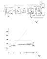
- the essential function of this processing chain is to perform first order low pass filtering on the setpoint torque T and take, as a setpoint flow, the square root of the filtering result. These operations are materialized in Figure 4 by a filter 40 followed by a circuit square root calculator 42. Other elements, not yet described, the processing chain can be omitted in some system operating conditions.
- the transfer function of the filter 40 is expressed by b / (a + s), where a and b are constants and s is the Laplace operator.
- FIG. 5 is intended to illustrate the performance gain obtained with a system according to the invention. It represents curves of energy consumption as a function of the speed of variation of the torque setpoint T.
- the tests were carried out with a sinusoidal torque setpoint varying between -10% and +10% of the nominal torque of the motor and of which the frequency ⁇ T is reported in radians per second.
- the energy consumed E is expressed in Joules over 4 s.
- a dashed curve represents the energy consumed in using a conventional constant flow system of the type of figure 1.
- the dotted curve represents the energy consumed using a conventional optimized system of the figure type 3.
- a family of solid lines represents energy consumed using a regulation system according to the invention.
- the constant flow system produces a substantially constant consumption of energy (in dashes) and of relatively high value.
- a conventional flux weakening circuit 44 described in connection with Figure 2, is arranged after the circuit 42 of square root calculation. This circuit 44 requires information speed ⁇ provided by the sensors 16 of the classic control system in Figure 1.
- the weakening circuit flow 44 decreases the output signal from circuit 42 gradually as a function of the speed beyond the saturation limit speed of the pulse width modulator.
Landscapes
- Engineering & Computer Science (AREA)
- Power Engineering (AREA)
- Control Of Ac Motors In General (AREA)
Applications Claiming Priority (3)
| Application Number | Priority Date | Filing Date | Title |
|---|---|---|---|
| FR9806554 | 1998-05-20 | ||
| FR9806554A FR2779017B1 (fr) | 1998-05-20 | 1998-05-20 | Systeme de regulation de moteur asynchrone a energie minimale par commande a flux oriente |
| US09/442,753 US6239574B1 (en) | 1998-05-20 | 1999-11-18 | Minimum energy regulation system for an asynchronous motor by field oriented control |
Publications (2)
| Publication Number | Publication Date |
|---|---|
| EP0959556A1 true EP0959556A1 (de) | 1999-11-24 |
| EP0959556B1 EP0959556B1 (de) | 2011-01-12 |
Family
ID=26234340
Family Applications (1)
| Application Number | Title | Priority Date | Filing Date |
|---|---|---|---|
| EP99410069A Expired - Lifetime EP0959556B1 (de) | 1998-05-20 | 1999-05-19 | Feldorientiertes Regelungssystem für Asynchronmotoren mit minimaler Energie |
Country Status (3)
| Country | Link |
|---|---|
| US (1) | US6239574B1 (de) |
| EP (1) | EP0959556B1 (de) |
| FR (1) | FR2779017B1 (de) |
Cited By (1)
| Publication number | Priority date | Publication date | Assignee | Title |
|---|---|---|---|---|
| CN103326659A (zh) * | 2013-07-05 | 2013-09-25 | 合肥工业大学 | 一种异步电机转子磁场定向校正的控制方法 |
Families Citing this family (3)
| Publication number | Priority date | Publication date | Assignee | Title |
|---|---|---|---|---|
| DE102006045044B3 (de) * | 2006-09-25 | 2008-06-12 | Vdo Automotive Ag | Verfahren und Regler zur Regelung eines stufenlosen elektrischen Getriebes |
| FR3025672B1 (fr) * | 2014-09-08 | 2016-11-04 | Renault Sa | Systeme et procede de commande d'une machine electrique asynchrone |
| FR3034927B1 (fr) | 2015-04-13 | 2017-04-07 | Renault Sas | Procede et systeme de commande d'une machine electrique asynchrone d'un groupe motopropulseur d'un vehicule automobile a traction electrique ou hybride. |
Citations (3)
| Publication number | Priority date | Publication date | Assignee | Title |
|---|---|---|---|---|
| US5444351A (en) * | 1993-07-06 | 1995-08-22 | Nissan Motor Co., Ltd. | System and method for controlling induction motor applicable to electric motor-driven vehicle |
| JPH08149897A (ja) * | 1994-11-14 | 1996-06-07 | Nissan Motor Co Ltd | 誘導機の磁束制御装置 |
| DE19615095C1 (de) * | 1996-04-17 | 1997-08-21 | Univ Dresden Tech | Verfahren zur Flußsollwertführung von Drehstrom-Asynchronmotoren |
Family Cites Families (1)
| Publication number | Priority date | Publication date | Assignee | Title |
|---|---|---|---|---|
| US6008618A (en) * | 1997-11-26 | 1999-12-28 | General Motors Corporation | Zero speed start-up for a speed sensorless induction motor drive |
-
1998
- 1998-05-20 FR FR9806554A patent/FR2779017B1/fr not_active Expired - Fee Related
-
1999
- 1999-05-19 EP EP99410069A patent/EP0959556B1/de not_active Expired - Lifetime
- 1999-11-18 US US09/442,753 patent/US6239574B1/en not_active Expired - Lifetime
Patent Citations (3)
| Publication number | Priority date | Publication date | Assignee | Title |
|---|---|---|---|---|
| US5444351A (en) * | 1993-07-06 | 1995-08-22 | Nissan Motor Co., Ltd. | System and method for controlling induction motor applicable to electric motor-driven vehicle |
| JPH08149897A (ja) * | 1994-11-14 | 1996-06-07 | Nissan Motor Co Ltd | 誘導機の磁束制御装置 |
| DE19615095C1 (de) * | 1996-04-17 | 1997-08-21 | Univ Dresden Tech | Verfahren zur Flußsollwertführung von Drehstrom-Asynchronmotoren |
Non-Patent Citations (2)
| Title |
|---|
| C. CANUDAS DE WIT, I. SELEME: "ROBUST TORQUE CONTROL DESIGN FOR INDUCTION MOTORS: THE MINIMUM ENERGY APPROACH", AUTOMATICA, vol. 33, no. 1, 1997, pages 63 - 79, XP002091541 * |
| PATENT ABSTRACTS OF JAPAN vol. 096, no. 010 31 October 1996 (1996-10-31) * |
Cited By (2)
| Publication number | Priority date | Publication date | Assignee | Title |
|---|---|---|---|---|
| CN103326659A (zh) * | 2013-07-05 | 2013-09-25 | 合肥工业大学 | 一种异步电机转子磁场定向校正的控制方法 |
| CN103326659B (zh) * | 2013-07-05 | 2015-10-28 | 合肥工业大学 | 一种异步电机转子磁场定向校正的控制方法 |
Also Published As
| Publication number | Publication date |
|---|---|
| EP0959556B1 (de) | 2011-01-12 |
| FR2779017A1 (fr) | 1999-11-26 |
| US6239574B1 (en) | 2001-05-29 |
| FR2779017B1 (fr) | 2000-06-23 |
Similar Documents
| Publication | Publication Date | Title |
|---|---|---|
| EP2719070B1 (de) | Verfahren zur steuerung des widerständigen drehmoments eines kraftfahrzeuggenerators und system zur durchführung dieses verfahrens | |
| EP2751923B1 (de) | Verfahren zur regelung eines generatorsatzes | |
| EP1104091A1 (de) | Autonomer elektrischer Generator, insbesondere für Flugzeuge | |
| FR2894735A1 (fr) | Generateur-moteur synchrone a enroulement de champ | |
| EP2926451B1 (de) | Verfahren zur regelung eines generatorsatzes | |
| WO2013030759A2 (fr) | Procede de regulation d'un groupe electrogene | |
| EP3166220B1 (de) | Vorrichtung zur dynamischen begrenzung, und verfahren zur dynamischen begrenzung durch eine solche vorrichtung | |
| EP0812059B1 (de) | Regelverfahren für eine Drehmaschine, Einrichtung zur Durchführung des Verfahrens und Anwendung der Einrichtung bei einer Drehmaschine | |
| EP0959556B1 (de) | Feldorientiertes Regelungssystem für Asynchronmotoren mit minimaler Energie | |
| FR3131992A1 (fr) | Procédé et système de commande d’une machine électrique pilotée par un onduleur pourvu de plusieurs bras de commutation avec deux méthodes d’asservissement | |
| EP1233506A1 (de) | Regelverfahren und Vorrichtung für eine rotierende elektrische Wechselstrommaschine, insbesondere Synchronmaschine | |
| EP1686682B1 (de) | Verfahren und System zur Begrenzung des Ausgangsstroms für einen V/f Umrichter | |
| EP0992105B1 (de) | Verfahren und vorrichtung zur steuerung der schalter in einem steuersystem mit variabeler struktur und steuerbarer frequenz | |
| EP0702451A1 (de) | Steuervorrichtung eines Synchronmotors | |
| FR3023997A1 (fr) | Architecture de modules electroniques de puissance interconnectes pour une machine electrique tournante hexaphasee et machine electrique tournante hexaphasee comprenant une telle architecture | |
| WO2015107297A1 (fr) | Procede de commande d'un module electronique de puissance apte a fonctionner en redresseur synchrone, dispositif de commande correspondant et machine electrique tournante de vehicule electrique comprenant un tel dispositif | |
| WO2026057745A1 (fr) | Procédé de contrôle d'un démarrage d'un moteur électrique, notamment un moteur d'entrainement d'un générateur d'un flux d'air | |
| EP3243271B1 (de) | Vorrichtung zur steuerung eines wechselstromgenerators eines kraftfahrzeugs und entsprechender wechselstromgenerator | |
| EP3861630B1 (de) | Umrichtersteuerung vorrichtung | |
| EP2033304B1 (de) | Verfahren zur steuerung einer an einen wärmemotor gekoppelten umwandelbaren elektrischen maschine, motor zur durchführung dieses verfahrens und dessen verwendung | |
| EP2193600A2 (de) | Verfahren zur steuerung der stromversorgung einer elektrischen maschine mit veränderlicher reluktanz | |
| FR2744301A1 (fr) | Onduleur d'alimentation d'un moteur electrique de traction d'un vehicule | |
| WO2026057746A1 (fr) | Procédé et dispositif de contrôle d'un moteur électrique à courant continu sans balais, notamment un moteur d'entrainement d'un générateur d'un flux d'air | |
| FR2536604A1 (fr) | Procede et dispositif pour piloter l'alimentation d'un moteur asynchrone utilisable notamment comme actionneur | |
| FR2517088A1 (fr) | Commande electrique pour reguler la vitesse et/ou la position d'une charge entrainee a tres faible vitesse de rotation |
Legal Events
| Date | Code | Title | Description |
|---|---|---|---|
| PUAI | Public reference made under article 153(3) epc to a published international application that has entered the european phase |
Free format text: ORIGINAL CODE: 0009012 |
|
| AK | Designated contracting states |
Kind code of ref document: A1 Designated state(s): CH DE GB IT LI SE |
|
| AX | Request for extension of the european patent |
Free format text: AL;LT;LV;MK;RO;SI |
|
| RAP1 | Party data changed (applicant data changed or rights of an application transferred) |
Owner name: SCHNEIDER ELECTRIC INDUSTRIES SA |
|
| 17P | Request for examination filed |
Effective date: 19991224 |
|
| RAP1 | Party data changed (applicant data changed or rights of an application transferred) |
Owner name: SCHNEIDER ELECTRIC INDUSTRIES SA |
|
| AKX | Designation fees paid |
Free format text: DE FR GB IT SE |
|
| RBV | Designated contracting states (corrected) |
Designated state(s): CH DE GB IT LI SE |
|
| RAP1 | Party data changed (applicant data changed or rights of an application transferred) |
Owner name: SCHNEIDER ELECTRONIC INDUSTRIES SAS |
|
| RAP1 | Party data changed (applicant data changed or rights of an application transferred) |
Owner name: SCHNEIDER ELECTRIC INDUSTRIES SAS |
|
| 17Q | First examination report despatched |
Effective date: 20071218 |
|
| RAP1 | Party data changed (applicant data changed or rights of an application transferred) |
Owner name: SCHNEIDER ELECTRIC INDUSTRIES SAS |
|
| GRAP | Despatch of communication of intention to grant a patent |
Free format text: ORIGINAL CODE: EPIDOSNIGR1 |
|
| GRAS | Grant fee paid |
Free format text: ORIGINAL CODE: EPIDOSNIGR3 |
|
| GRAA | (expected) grant |
Free format text: ORIGINAL CODE: 0009210 |
|
| RIN1 | Information on inventor provided before grant (corrected) |
Inventor name: GEORGES, DIDIER Inventor name: RAMIREZ, JOSE MIGUEL Inventor name: CANUDAS DE WIT, CARLOS |
|
| AK | Designated contracting states |
Kind code of ref document: B1 Designated state(s): CH DE GB IT LI SE |
|
| REG | Reference to a national code |
Ref country code: GB Ref legal event code: FG4D Free format text: NOT ENGLISH |
|
| REG | Reference to a national code |
Ref country code: CH Ref legal event code: EP |
|
| REF | Corresponds to: |
Ref document number: 69943118 Country of ref document: DE Date of ref document: 20110224 Kind code of ref document: P |
|
| REG | Reference to a national code |
Ref country code: DE Ref legal event code: R096 Ref document number: 69943118 Country of ref document: DE Effective date: 20110224 |
|
| REG | Reference to a national code |
Ref country code: SE Ref legal event code: TRGR |
|
| PLBE | No opposition filed within time limit |
Free format text: ORIGINAL CODE: 0009261 |
|
| STAA | Information on the status of an ep patent application or granted ep patent |
Free format text: STATUS: NO OPPOSITION FILED WITHIN TIME LIMIT |
|
| 26N | No opposition filed |
Effective date: 20111013 |
|
| REG | Reference to a national code |
Ref country code: DE Ref legal event code: R097 Ref document number: 69943118 Country of ref document: DE Effective date: 20111013 |
|
| PGFP | Annual fee paid to national office [announced via postgrant information from national office to epo] |
Ref country code: GB Payment date: 20150518 Year of fee payment: 17 Ref country code: SE Payment date: 20150515 Year of fee payment: 17 Ref country code: CH Payment date: 20150506 Year of fee payment: 17 Ref country code: DE Payment date: 20150421 Year of fee payment: 17 |
|
| PGFP | Annual fee paid to national office [announced via postgrant information from national office to epo] |
Ref country code: IT Payment date: 20150512 Year of fee payment: 17 |
|
| REG | Reference to a national code |
Ref country code: DE Ref legal event code: R119 Ref document number: 69943118 Country of ref document: DE |
|
| REG | Reference to a national code |
Ref country code: CH Ref legal event code: PL |
|
| GBPC | Gb: european patent ceased through non-payment of renewal fee |
Effective date: 20160519 |
|
| PG25 | Lapsed in a contracting state [announced via postgrant information from national office to epo] |
Ref country code: LI Free format text: LAPSE BECAUSE OF NON-PAYMENT OF DUE FEES Effective date: 20160531 Ref country code: CH Free format text: LAPSE BECAUSE OF NON-PAYMENT OF DUE FEES Effective date: 20160531 |
|
| PG25 | Lapsed in a contracting state [announced via postgrant information from national office to epo] |
Ref country code: SE Free format text: LAPSE BECAUSE OF NON-PAYMENT OF DUE FEES Effective date: 20160520 Ref country code: IT Free format text: LAPSE BECAUSE OF NON-PAYMENT OF DUE FEES Effective date: 20160519 |
|
| PG25 | Lapsed in a contracting state [announced via postgrant information from national office to epo] |
Ref country code: DE Free format text: LAPSE BECAUSE OF NON-PAYMENT OF DUE FEES Effective date: 20161201 |
|
| PG25 | Lapsed in a contracting state [announced via postgrant information from national office to epo] |
Ref country code: GB Free format text: LAPSE BECAUSE OF NON-PAYMENT OF DUE FEES Effective date: 20160519 |