EP0812936A2 - Platte zum gleichzeitigen SZ Falschzwirnen - Google Patents
Platte zum gleichzeitigen SZ Falschzwirnen Download PDFInfo
- Publication number
- EP0812936A2 EP0812936A2 EP97108328A EP97108328A EP0812936A2 EP 0812936 A2 EP0812936 A2 EP 0812936A2 EP 97108328 A EP97108328 A EP 97108328A EP 97108328 A EP97108328 A EP 97108328A EP 0812936 A2 EP0812936 A2 EP 0812936A2
- Authority
- EP
- European Patent Office
- Prior art keywords
- disc
- friction surface
- false
- twist
- simultaneous
- Prior art date
- Legal status (The legal status is an assumption and is not a legal conclusion. Google has not performed a legal analysis and makes no representation as to the accuracy of the status listed.)
- Withdrawn
Links
- 230000007423 decrease Effects 0.000 description 8
- 230000002093 peripheral effect Effects 0.000 description 8
- 241001589086 Bellapiscis medius Species 0.000 description 7
- 229920003051 synthetic elastomer Polymers 0.000 description 3
- 239000005061 synthetic rubber Substances 0.000 description 3
- 238000005299 abrasion Methods 0.000 description 2
- 238000010276 construction Methods 0.000 description 2
- 230000003247 decreasing effect Effects 0.000 description 2
- 235000004879 dioscorea Nutrition 0.000 description 2
- 239000000463 material Substances 0.000 description 2
- 239000013589 supplement Substances 0.000 description 2
- 244000043261 Hevea brasiliensis Species 0.000 description 1
- 239000006185 dispersion Substances 0.000 description 1
- 229920001971 elastomer Polymers 0.000 description 1
- 238000010438 heat treatment Methods 0.000 description 1
- 239000002184 metal Substances 0.000 description 1
- 238000000034 method Methods 0.000 description 1
- 229920003052 natural elastomer Polymers 0.000 description 1
- 229920001194 natural rubber Polymers 0.000 description 1
- 239000005060 rubber Substances 0.000 description 1
- 238000004073 vulcanization Methods 0.000 description 1
Images



Classifications
-
- D—TEXTILES; PAPER
- D02—YARNS; MECHANICAL FINISHING OF YARNS OR ROPES; WARPING OR BEAMING
- D02G—CRIMPING OR CURLING FIBRES, FILAMENTS, THREADS, OR YARNS; YARNS OR THREADS
- D02G1/00—Producing crimped or curled fibres, filaments, yarns, or threads, giving them latent characteristics
- D02G1/02—Producing crimped or curled fibres, filaments, yarns, or threads, giving them latent characteristics by twisting, fixing the twist and backtwisting, i.e. by imparting false twist
- D02G1/04—Devices for imparting false twist
- D02G1/08—Rollers or other friction causing elements
- D02G1/082—Rollers or other friction causing elements with the periphery of at least one disc
Definitions
- the present invention relates to a disc for simultaneous SZ false twisting used in a SZ false twisting and more particularly, relates to a device for making the contact pressure on the yarns uniform.
- a SZ simultaneous false twister is known where two yarns are doubled and wound after being applied with an S twist and Z twist respectively.
- a non-torque yarn is obtained where the torque of the S-twist and torque of the Z-twist are cancelled out, the unwinding properties and selvedge of the yarn improve and an increase in operating speed of the subsequent process and decrease in the number of stationary machines can be expected.
- This kind of SZ simultaneous false twister comprises the independent adjacent positioning of a false twist device that imparts an S-twist and a false twist device that imparts an Z-twist.
- a typical example of this kind of false twister is the running of a pair of belt members in different direction at right angles to each other and the imparting of a false twist in the yarn by the contact surface (nip surface) of the cross over part.
- a compact false twist device where a ring shaped elastic member comprising a first friction surface and second friction surface on either side of the outer periphery of a disc and the arrangement of a pair of false twist members against each of the first friction surface and second friction surface.
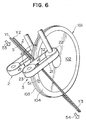
- the false twist device comprises a disc for simultaneous SZ false twisting 101, a first false twist member 2 and a second false twist member 3.
- the disc for simultaneous SZ false twisting 101 is arranged with a first friction ring member 103 and a second friction ring member 104 on either side of the outer periphery of the disc 102.
- the first false twist member 2 and second false twist member 3 have the same construction and are wound with a continuous belt member 21 between a drive pulley 22 and a free pulley 23.
- the belt member 21 of the second false twist member 3 and the tangential direction of the second friction ring member 104 are positioned such that the cross over angle is ⁇ .
- This second friction ring member 104 rotates in the direction of arrow 51 and as the belt member 23 runs in the direction of arrow 52, the cross over part forms contact surfaces (nip surfaces) that move in opposite direction to each other enabling a twist to be imparted in the yarn.
- first false twist member 2 is of similar arrangement.
- the pair of yarns Y1, Y2 are inserted in the contact surfaces (nip surfaces) along the bisector of the angle ⁇ as shown by arrow 53, an S-twist is imparted in yarn Y1, a Z-twist is imparted in yarn Y2 and the two are doubled in a position separated from the disc for simultaneous SZ false twisting 101 producing a single yarn Y3 pulled in the direction of arrow 54.
- a false twister using the above mentioned disc for simultaneous SZ false twisting 101 the first false twist member 2 and second false twist member 3 forms a compact device and excels due to the fact that the running path of the yarn is very simple with this device.
- the twist easily becomes unstable and there are limitations on the twist count and the like.
- a first aspect of the present invention is a disc for simultaneous SZ false twisting arranged with a a ring shaped elastic member forming a first friction surface and second friction surface on either side of the outer periphery of the disc and which imparts a false twist in opposite directions in a pair of yarns at each of the first friction surface and second friction surface, wherein each of the first friction surface and second friction surface of the elastic member are convex shaped.
- a pair of false twist members are able to contact the first friction surface and second friction surface respectively and a false twist is imparted in opposite direction in a pair of yams by this contact surface (nip surface).
- the false twist member more easily flexes and the contact pressure of the contact surfaces more easily becomes uneven but by making each of the first friction surface and second friction surface convex shaped with prior reference to the flexion of the false twist member, the contact pressure becomes uniform.
- a typical example of the false twist members are belt members but as belt members are wound around a pair of pulleys and contact the first and second friction surfaces, the contact pressure of the contact surfaces easily becomes unstable by the curve or hollow of the belt members thus convex shaped first and second friction surfaces supplement the hollow of the belt members and ensure uniform contact surfaces.
- the degree of convex shape of the first and second friction surfaces prefferably be enough to supplement any deformation of the false twist member with respect to the friction surfaces.
- a pair of belt members which are able to contact a first friction surface and second friction surface respectively and where the width of the first friction surface and second friction surface of the elastic member is approximately the same as the width of the aforementioned belt members. Accordingly, the contact surface produced by the friction surfaces and belt members is of a balanced shape.
- the elastic member has a concave cross section that fits with the outer periphery of the disc. Accordingly, the positioning of the elastic member on the disc is simple.
- Figure 1 is a drawing showing the structure of the disc for simultaneous SZ false twisting of the present invention.
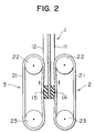
- Figure 2 is a drawing showing the operations of the disc for simultaneous SZ false twisting of the present invention.
- Figure 3 is a device construction of the false twister using the disc for simultaneous SZ false twisting of the present invention.
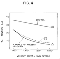
- Figure 4 is a graph showing the performance of the disc for simultaneous SZ false twisting of the present invention.
- Figure 5 is a graph showing the performance of the disc for simultaneous SZ false twisting of the present invention.
- Figure 6 is a drawing showing the structure of a conventional disc for simultaneous SZ false twisting.
- Figure 1A is a cross section of a disc for simultaneous SZ false twisting 1 and Figure 1B is side view of the disc for simultaneous SZ false twisting 1.
- the disc for simultaneous SZ false twisting 1 comprises a disc 4 and elastic member 5 having a concave cross section in a state where it is fitted to the outer periphery of the disc 4.
- the disc 4 is formed as rigid body such as a metal disc or the like and the elastic member 5 is an elastic body such as synthetic rubber or natural rubber or the like.
- the disc 4 and elastic member 5 are fixed by fitting as a result of heat attachment, adhesion or their concave cross section.
- the part along both side surfaces of the elastic member 5 of the outer periphery of the disc 4 forms a first friction surface 11 and second friction surface 12.
- the false twist device is formed by a first false twist member 2 being positioned against the first friction member 11 and a second false twist member 3 being positioned against the second friction member 12.
- the arrangement of the first false twist member 2 and second false twist member 3 is similar to that described as in Figure 6 and the description of such is omitted as it has the same numbering.
- the cross section of the first friction surface 11 and second friction surface 12 are not flat parallel surfaces but form a convex shape having a curve of radius R.
- This convex shape is symmetrical to the left and right of the center of the thicker direction of the disc 4 and for example, is formed by the abrasion of a whetstone 13 having a convex shape.
- the elastic member 5 is fixed to the disc 4 by heating.
- a device preprepared with raw rubber in a concave shape is fitted onto the disc 4 and baking is performed on the disc 4 at the same time as vulcanization by heat and pressure application. Thereafter, the first friction surface 11 and second friction surface 12 are formed by abrasion by a whetstone 13.
- the surface 55 of the inner peripheral side and surface 56 of the outer peripheral side of the elastic member 5 are processed by grinding and formed to an elastic member 5 having a predetermined inner and outer diameter and predetermined width W1. If the cross section is concave shaped, the processing of the surface of the outer peripheral side is also simple.
- the distance ⁇ between the outer peripheral surface 56 of the elastic member 5 and the outer peripheral surface of the disc 4 is as small as possible. The reason for this is so the first friction surface 11 and second friction surface 12 may be reliably formed. As a result, the dimensions of each member are adjusted so that ⁇ is from 0.5mm to 2mm.
- Figure 1B shows a false twist device being a combination of the disc for simultaneous SZ false twisting 1 and the first and second false twist members 2, 3. It is preferable for the width W2 of the belt member 21 of the first and second false twist members 2, 3 to be approximately the same as the width W1 of the elastic member 5.
- the belt member 21 of the first false twist member 2 is in contact with the first friction surface 11 of the disc for simultaneous SZ false twisting 1 at an angle and form a first contact surface (nip surface) 14.
- the belt member 21 of the second false twist member 3 is in contact with the second friction surface 12 and form a second contact surface (nip surface) 15.
- the belt member 21 is stretched between pulleys 22, 23 at a predetermined tension and as there is not support midway, flexion develops.
- the first friction surface 11 and second friction surface 12 are formed in convex shapes of radius R in order to counteract this flexion, the dispersion of the contact pressure between the surfaces of the first contact surface 14 and second contact surface 15 is reduced. As a result, the yarn twisted by the first contact surface 14 and second contact surface 15 receives a stable twist application.
- the convex shape of the first friction surface 11 and the second friction surface 12 is decided corresponding to the deformation of the respective false twist members.
- both pulleys 22, 23 are long and the tension of the belt members is low, the convex part becomes a more projecting shape.
- the deformation of the false twist members is small, the convex shape is also small.
- the convex shape is only to counteract the flexion of the false twist members, is not limited to the arc-shape of radius R, and may be parabolic, elliptical or angular.
- the contact surfaces 14, 15 resemble a rhombus. Due to this, a twist insufficiency due to width W1 being too small or a decrease in the lifespan of the belt member 21 due to the width W1 being too large is prevented.
- the yarn Y1 from a first POY and the yarn Y2 from a second POY are pulled by a first feed roller FR1. From downstream, a heater H1 and false twist device 31 are sequentially positioned between the first feed roller FR1 and a second feed roller FR2.
- the peripheral speed of the second feed roller FR2 is higher than the peripheral speed of the first feed roller FR1 and drawing occurs between the two.
- the yams Y1,Y2 between the false twist device 31 and first feed roller FR1 are in a twisted state and the twist is heat fixed by the heater H1.
- the yarns Y1,Y2 between the false twist device 31 and second feed roller FR2 are in an untwisted state and are pulled by the second feed roller FR2 while being combined.
- the filaments of the two yarns Y1,Y2 are entangled at nozzle I/L forming a single yarn Y3 wound onto DTY. Due to this, the torques of the S-twist yarn and Z-twist yarn are completely removed and a non-torque yarn is produced.
- Draw texturizing of a 150d/36f yarn was performed with a yarn speed of 800m/min and a speed ratio between the first feed roller FR1 and second feed roller FR2 of 1.60.
- the material of the elastic member 5 was synthetic rubber having a width W1 of 8mm and a diameter of 178mm.
- the material of the belt member 21 of the first and second false twist member 2, 3 opposing the elastic member 5 was synthetic rubber with a width W1 of 8mm and a thickness of 1.6mm. Also, the cross over angle ⁇ of the tangential direction of the elastic member 5 and the belt member 21 was 105 ° .
- the false twist members for example belt members
- the contact pressure of the contact surfaces which impart a twist in the yarn becomes uniform and a false twist having a stable tension is imparted.
- the untwisting side tension (T 2 tension) decreases, the twist count can be increased and the generation of untwisted parts can be decreased.
- the elastic member may be easily attached to the outer periphery of the disc and a high precision disc for simultaneous SZ false twisting can be produced at low cost.
Landscapes
- Engineering & Computer Science (AREA)
- Mechanical Engineering (AREA)
- Textile Engineering (AREA)
- Yarns And Mechanical Finishing Of Yarns Or Ropes (AREA)
- Gas Burners (AREA)
Applications Claiming Priority (2)
| Application Number | Priority Date | Filing Date | Title |
|---|---|---|---|
| JP17307996A JP3564877B2 (ja) | 1996-06-11 | 1996-06-11 | Sz同時仮撚用円盤 |
| JP173079/96 | 1996-06-11 |
Publications (2)
| Publication Number | Publication Date |
|---|---|
| EP0812936A2 true EP0812936A2 (de) | 1997-12-17 |
| EP0812936A3 EP0812936A3 (de) | 1997-12-29 |
Family
ID=15953823
Family Applications (1)
| Application Number | Title | Priority Date | Filing Date |
|---|---|---|---|
| EP97108328A Withdrawn EP0812936A3 (de) | 1996-06-11 | 1997-05-22 | Platte zum gleichzeitigen SZ Falschzwirnen |
Country Status (4)
| Country | Link |
|---|---|
| EP (1) | EP0812936A3 (de) |
| JP (1) | JP3564877B2 (de) |
| KR (1) | KR980002324A (de) |
| CN (1) | CN1174253A (de) |
Cited By (1)
| Publication number | Priority date | Publication date | Assignee | Title |
|---|---|---|---|---|
| EP0864677A1 (de) * | 1997-03-14 | 1998-09-16 | Murata Kikai Kabushiki Kaisha | Fadenspannungsregelung für Texturiervorrichtung zum Falschdrallzwirnen eines Zwirns |
Families Citing this family (1)
| Publication number | Priority date | Publication date | Assignee | Title |
|---|---|---|---|---|
| JP5669743B2 (ja) * | 2008-11-04 | 2015-02-12 | セラムテック ゲゼルシャフト ミット ベシュレンクテル ハフツングCeramTec GmbH | 摩擦円板 |
Family Cites Families (7)
| Publication number | Priority date | Publication date | Assignee | Title |
|---|---|---|---|---|
| DE2518538B1 (de) * | 1975-04-25 | 1976-01-29 | Kugelfischer G Schaefer & Co | Reibscheibe |
| US4027467A (en) * | 1976-06-04 | 1977-06-07 | Smith Joseph F | Uniroll false twist device and method |
| US4377932A (en) * | 1979-07-14 | 1983-03-29 | Barmag Barmer Maschinenfabrik Ag | Flexible belt yarn false twisting apparatus |
| US4391091A (en) * | 1981-03-17 | 1983-07-05 | Barmag Barmer Maschinenfabrik Ag | False twisting apparatus and method |
| US4823545A (en) * | 1987-08-31 | 1989-04-25 | Maschinenfabrik Rieter Ag | Method of and apparatus for false-twist spinning |
| US4936087A (en) * | 1987-11-19 | 1990-06-26 | Murata Kikai Kabushiki Kaisha | Belt type false twisting device |
| JP2951209B2 (ja) * | 1994-07-11 | 1999-09-20 | 村田機械株式会社 | 合糸用仮撚り装置 |
-
1996
- 1996-06-11 JP JP17307996A patent/JP3564877B2/ja not_active Expired - Lifetime
-
1997
- 1997-03-07 KR KR1019970007627A patent/KR980002324A/ko not_active Abandoned
- 1997-03-26 CN CN 97103719 patent/CN1174253A/zh active Pending
- 1997-05-22 EP EP97108328A patent/EP0812936A3/de not_active Withdrawn
Cited By (1)
| Publication number | Priority date | Publication date | Assignee | Title |
|---|---|---|---|---|
| EP0864677A1 (de) * | 1997-03-14 | 1998-09-16 | Murata Kikai Kabushiki Kaisha | Fadenspannungsregelung für Texturiervorrichtung zum Falschdrallzwirnen eines Zwirns |
Also Published As
| Publication number | Publication date |
|---|---|
| KR980002324A (ko) | 1998-03-30 |
| CN1174253A (zh) | 1998-02-25 |
| EP0812936A3 (de) | 1997-12-29 |
| JP3564877B2 (ja) | 2004-09-15 |
| JPH101832A (ja) | 1998-01-06 |
Similar Documents
| Publication | Publication Date | Title |
|---|---|---|
| CA1073285A (en) | Self twist yarn strand system | |
| TWI425127B (zh) | Clamp type false twisting device | |
| US4276740A (en) | Self-twisted yarn and method and apparatus for producing it | |
| JPS638210B2 (de) | ||
| US4033103A (en) | Process and apparatus for producing a variable diameter alternate twist yarn | |
| US4296598A (en) | Apparatus for providing false twist to moving yarn | |
| US4103481A (en) | Variable diameter yarn | |
| EP0812936A2 (de) | Platte zum gleichzeitigen SZ Falschzwirnen | |
| US4402178A (en) | Textured multifilament yarn having alternating twists | |
| US3724196A (en) | High speed texturing of synthetic continuous filament yarn | |
| US4523428A (en) | Process for manufacturing textured multifilament yarn having alternating twist | |
| US2997837A (en) | Slub yarn product | |
| CA1135577A (en) | False twist machine | |
| WO1990004668A1 (en) | Improvements in or relating to ring spinning | |
| JPH10121342A (ja) | 弾性糸の給糸方法 | |
| JPS5917209B2 (ja) | 特殊交互撚糸 | |
| JPH0280628A (ja) | 複合撚り糸の製造方法 | |
| CN121496630B (zh) | 一种基于动态捻度控制的花式纱的纺纱方法 | |
| CN1097104C (zh) | 假捻发生器 | |
| JPH02216228A (ja) | 糸の仮撚方法及びその仮撚装置 | |
| GB2119820A (en) | Process and apparatus for making yarn from roving | |
| US3879927A (en) | False twisting device | |
| JPS6065122A (ja) | 紡績糸の製造方法 | |
| EP0052678B1 (de) | Verfahren zur Herstellung eines texturierten, alternierenden Drall aufweisenden Multifilamentgarn | |
| JPH062970B2 (ja) | スラブヤ−ン及びその製造方法 |
Legal Events
| Date | Code | Title | Description |
|---|---|---|---|
| PUAI | Public reference made under article 153(3) epc to a published international application that has entered the european phase |
Free format text: ORIGINAL CODE: 0009012 |
|
| PUAL | Search report despatched |
Free format text: ORIGINAL CODE: 0009013 |
|
| AK | Designated contracting states |
Kind code of ref document: A2 Designated state(s): DE FR IT |
|
| AK | Designated contracting states |
Kind code of ref document: A3 Designated state(s): DE FR IT |
|
| 17P | Request for examination filed |
Effective date: 19980210 |
|
| GRAG | Despatch of communication of intention to grant |
Free format text: ORIGINAL CODE: EPIDOS AGRA |
|
| STAA | Information on the status of an ep patent application or granted ep patent |
Free format text: STATUS: THE APPLICATION HAS BEEN WITHDRAWN |
|
| 17Q | First examination report despatched |
Effective date: 20000505 |
|
| 18W | Application withdrawn |
Withdrawal date: 20000522 |