EP0812954A1 - Rouleau de presse - Google Patents
Rouleau de presse Download PDFInfo
- Publication number
- EP0812954A1 EP0812954A1 EP97106857A EP97106857A EP0812954A1 EP 0812954 A1 EP0812954 A1 EP 0812954A1 EP 97106857 A EP97106857 A EP 97106857A EP 97106857 A EP97106857 A EP 97106857A EP 0812954 A1 EP0812954 A1 EP 0812954A1
- Authority
- EP
- European Patent Office
- Prior art keywords
- piston
- press
- roll according
- press roll
- cylinder
- Prior art date
- Legal status (The legal status is an assumption and is not a legal conclusion. Google has not performed a legal analysis and makes no representation as to the accuracy of the status listed.)
- Granted
Links
- 230000002706 hydrostatic effect Effects 0.000 claims description 23
- 239000012530 fluid Substances 0.000 claims description 10
- 238000007789 sealing Methods 0.000 claims description 8
- 239000000463 material Substances 0.000 claims description 7
- 238000005452 bending Methods 0.000 claims description 2
- 239000011248 coating agent Substances 0.000 claims description 2
- 238000000576 coating method Methods 0.000 claims description 2
- 230000000694 effects Effects 0.000 claims description 2
- 239000002184 metal Substances 0.000 claims 1
- 239000011111 cardboard Substances 0.000 abstract description 3
- 239000011087 paperboard Substances 0.000 abstract description 3
- 238000005553 drilling Methods 0.000 description 4
- 230000005484 gravity Effects 0.000 description 2
- 239000000314 lubricant Substances 0.000 description 2
- OKTJSMMVPCPJKN-UHFFFAOYSA-N Carbon Chemical compound [C] OKTJSMMVPCPJKN-UHFFFAOYSA-N 0.000 description 1
- 239000004698 Polyethylene Substances 0.000 description 1
- 241000251131 Sphyrna Species 0.000 description 1
- 229910052799 carbon Inorganic materials 0.000 description 1
- 238000009434 installation Methods 0.000 description 1
- 238000004519 manufacturing process Methods 0.000 description 1
- INHWXZFVSTUXPN-UHFFFAOYSA-J molybdenum(4+) disulfite Chemical compound [Mo+4].[O-]S([O-])=O.[O-]S([O-])=O INHWXZFVSTUXPN-UHFFFAOYSA-J 0.000 description 1
- 239000000123 paper Substances 0.000 description 1
- -1 polyethylene Polymers 0.000 description 1
- 229920000573 polyethylene Polymers 0.000 description 1
- 239000004810 polytetrafluoroethylene Substances 0.000 description 1
- 229920001343 polytetrafluoroethylene Polymers 0.000 description 1
Images


Classifications
-
- D—TEXTILES; PAPER
- D21—PAPER-MAKING; PRODUCTION OF CELLULOSE
- D21F—PAPER-MAKING MACHINES; METHODS OF PRODUCING PAPER THEREON
- D21F3/00—Press section of machines for making continuous webs of paper
- D21F3/02—Wet presses
- D21F3/0209—Wet presses with extended press nip
- D21F3/0218—Shoe presses
-
- D—TEXTILES; PAPER
- D21—PAPER-MAKING; PRODUCTION OF CELLULOSE
- D21G—CALENDERS; ACCESSORIES FOR PAPER-MAKING MACHINES
- D21G1/00—Calenders; Smoothing apparatus
- D21G1/02—Rolls; Their bearings
- D21G1/0206—Controlled deflection rolls
- D21G1/0213—Controlled deflection rolls with deflection compensation means acting between the roller shell and its supporting member
- D21G1/022—Controlled deflection rolls with deflection compensation means acting between the roller shell and its supporting member the means using fluid pressure
-
- F—MECHANICAL ENGINEERING; LIGHTING; HEATING; WEAPONS; BLASTING
- F16—ENGINEERING ELEMENTS AND UNITS; GENERAL MEASURES FOR PRODUCING AND MAINTAINING EFFECTIVE FUNCTIONING OF MACHINES OR INSTALLATIONS; THERMAL INSULATION IN GENERAL
- F16C—SHAFTS; FLEXIBLE SHAFTS; ELEMENTS OR CRANKSHAFT MECHANISMS; ROTARY BODIES OTHER THAN GEARING ELEMENTS; BEARINGS
- F16C13/00—Rolls, drums, discs, or the like; Bearings or mountings therefor
- F16C13/02—Bearings
- F16C13/022—Bearings supporting a hollow roll mantle rotating with respect to a yoke or axle
- F16C13/024—Bearings supporting a hollow roll mantle rotating with respect to a yoke or axle adjustable for positioning, e.g. radial movable bearings for controlling the deflection along the length of the roll mantle
- F16C13/026—Bearings supporting a hollow roll mantle rotating with respect to a yoke or axle adjustable for positioning, e.g. radial movable bearings for controlling the deflection along the length of the roll mantle by fluid pressure
- F16C13/028—Bearings supporting a hollow roll mantle rotating with respect to a yoke or axle adjustable for positioning, e.g. radial movable bearings for controlling the deflection along the length of the roll mantle by fluid pressure with a plurality of supports along the length of the roll mantle, e.g. hydraulic jacks
Definitions
- the invention relates to a press roll for treating a material web in a press nip formed with a counter surface, with a press shoe extending along the press nip, a press jacket guided over the press shoe, and in particular several force elements supported on a stationary support and arranged one behind the other in the direction of the roll axis are preferably each actuated by pressure fluid and are formed by a cylinder / piston unit and by means of the movable piston or the like of which the press shoe can be acted upon in order to press the press jacket against the counter surface.
- a press roll of this type is known for example from EP 0 345 501 B1.
- the manufacturing costs and the assembly effort depend to a considerable extent on the desired degree of uniformity of the line force distribution along the press nip across the material web to be treated, which can be a paper or cardboard web in particular.
- C is a constant that takes into account the elastic flexibility of the press shoe.
- P L indicates the line force and t the span between the force elements.
- the span is particularly critical with regard to an even line force distribution.
- the line force becomes smaller at the points where the press shoe sags. With greater sag and less Compressibility of the material web guided through the press nip can even reduce the line force in the middle between the force elements to zero.
- a double-row arrangement of force elements is provided in the press roll known from EP 0 345 501 B1, in which the two parallel rows of force elements each extend transversely to the material web along the roll axis.
- the known double-row arrangement has the advantage that, with the same piston area formed by the individual pistons as a whole, the support distance between the force elements in the direction of the roller axis is halved.
- the number of force elements formed by a respective cylinder / piston unit increases fourfold.
- the aim of the invention is to provide a press roll of the type mentioned which, with a compact structure and in particular minimal radial space requirement and with a minimal number of force elements, in particular also with an optimal line force distribution across the press nip across the press nip, depending on the roller, different force element division.
- the piston of at least one force element and / or an opposite region of the press shoe is designed such that the supporting forces occurring between the piston and the press shoe are concentrated at least essentially in mutually opposite piston edge regions arranged on different sides of a piston center plane perpendicular to the roller axis.
- the invention is therefore essentially based on the idea of not centrally supporting the piston of a respective force element against the press shoe, but rather concentrating the supporting forces between the piston and the press shoe more or less in opposite directions of the roller axis in the direction of the piston edges. As a result, this leads to a reduction in the effective span between the force elements and thus, corresponding to the relationship mentioned at the outset, to a reduction of the maximum sag of the press shoe between the support points by the power of four.
- the desired concentration of supporting forces is brought about in that the piston and / or the press shoe is provided with at least two discrete, raised contact surfaces which are spaced apart in the direction of the roller axis.
- At least the contact surfaces are expediently each provided with, for example, a glued-on or galvanically applied sliding coating, which consists of a layer of a material which has a particularly low coefficient of friction with a metallic counter surface, for example tissue mixed with lubricant, the lubricants being PTFE, molybdenum sulfite, polyethylene or can be lamellar carbon, or galvanically applied thin layers.
- Optimal results can be achieved if the distance between the centroids of the two discrete contact surfaces measured in the direction of the roller axis is at least equal to half the piston pitch of the pistons of a plurality of force elements arranged one behind the other in the direction of the roller axis, and preferably greater than this half piston pitch, so that an axial distance between the centroids of the adjacent contact surfaces of adjacent pistons results which is smaller than half the piston pitch.
- At least one hydrostatic pocket preferably arranged in the region of the center of the piston, can be provided between these contact surfaces, so that in any case a disruptive sag in the central region of the piston is also excluded.
- the concentration of supporting forces on the piston edge region is brought about by an annular hydrostatic pocket which is arranged between the piston and the press shoe and is preferably provided in the piston.
- a respective hydrostatic pocket provided in the piston can be connected via a throttle to the cylinder chamber of the force element formed by a cylinder / piston unit, or it can also be pressurized with pressure fluid independently of the cylinder pressure chamber.
- a pressure-free pocket formed in the piston can be provided within the ring pocket, into which a relief bore leading to the outside preferably opens.
- the piston which is preferably designed as a flat piston without a piston rod, is expediently secured against rotation by at least one elastic support which is arranged between it and the stationary carrier or the cylinder base and is eccentric to the piston axis.
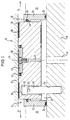
- FIG. 1 and 2 show part of a press roll 10, which is used to treat a material web, such as in particular a paper or cardboard web, in a press nip (not shown) formed with a counter surface.
- a material web such as in particular a paper or cardboard web
- the press roll 10 comprises a press shoe 12 which extends along the press nip, a press jacket (not shown) which is guided over the press shoe 12 and a plurality of force elements 14 which are arranged one behind the other in the direction of the roll axis X and are each actuated by pressure fluid and formed by a cylinder / piston unit (only one shown), by means of the movable piston 16 of the press shoe 12 can be acted upon in order to press the press jacket against the counter surface, which can be formed by a counter roll.
- the force elements 14 are fastened to a stationary support 18 on the side facing away from the press shoe 12.
- the respective piston 16 designed as a flat piston without a piston rod is guided in a flat, bottomless cylinder part 20 of the force element 14.
- This flat, bottomless cylinder part 20 is supported on the underside (cf. FIG. 1) on the stationary support 18 and is sealed off by the latter to form a pressure chamber acting on the piston 16.
- an annular seal 24 is provided between the cylinder part 20 and the stationary support 18.
- the cylinder part 20 has at its upper end facing the press shoe 12 an inner collar 26 which is provided with an inwardly open annular groove 28 into which an annular seal 30 bearing against the outer circumference of the piston 16 is inserted.
- the cylinder part 20 itself is inserted into a corresponding groove-shaped receptacle 32 in the carrier 18, which extends in the axial direction X.
- the piston 16 of the force element 14 is now designed so that the supporting forces occurring between it and the press shoe 12 are concentrated at least essentially in opposite piston edge regions arranged on different sides of a piston center plane 34 perpendicular to the roller axis X.
- the piston 14 is provided with two discrete raised contact surfaces which are spaced apart from one another in the direction of the roller axis X and which bring about the concentration of supporting forces, which in the present case are formed by interchangeable contact plates 36.
- a contact plate 36 is arranged on each side of the piston center plane 34.
- Each of these contact plates 36 is also preferably provided with e.g. galvanically applied sliding surface.
- the contact plates 36 have an essentially kidney-shaped shape in the present case.
- the distance 2a measured in the direction of the roller axis X between the centroids S of the two discrete contact surfaces formed by the contact plates 36 is at least equal to half the piston pitch t of the pistons and a plurality of force elements 14 arranged one behind the other in the direction of the roller axis X.
- This distance is preferably 2a between the two centroids S greater than half the piston pitch, so that there is an axial distance s between the centroids S of the adjacent contact surfaces of adjacent pistons that is smaller than this half piston pitch.
- the distance a indicates the distance between a respective center of area S and the piston center plane 34.
- the piston 16 has a hydrostatic pocket 38 which is arranged in the region of the center of the piston and which is surrounded on the outside by a slide and / or sealing ring 40 which is provided on the piston 16 and cannot be lost and is elastically pressed against the press shoe 12.
- This sealing ring is held captive on the piston 16 by a retaining ring 42.
- the piston 16 has a relatively high bending stiffness in the direction of the roller axis X, which is preferably at least as large as that of the press shoe 12.
- the hydrostatic pocket 38 provided in the piston 16 is connected to the pressure chamber 22 of the force element 14 formed by a cylinder / piston unit via a bore 44 which preferably acts as a throttle.
- the pressure chamber 22 is supplied with pressure fluid via a channel 46 provided in the carrier 18, which can in turn be connected to a pressure fluid line passing through the carrier 18.
- the piston 16 is thus acted upon via the pressure chamber 22 and the hydrostatic pocket 38 is supplied with pressure fluid.
- the piston 16 is secured against rotation by an elastic support which is arranged between it and the stationary support 18 and is eccentric to the piston axis, which in the present case is formed by a leaf spring 48 with a hammer head 50, the end of which on the hammer head side is inserted into a bore 52 on the piston side and the other end of which is excessively pressed into a bore 54 provided in the stationary support 18.
- an elastic support which is arranged between it and the stationary support 18 and is eccentric to the piston axis, which in the present case is formed by a leaf spring 48 with a hammer head 50, the end of which on the hammer head side is inserted into a bore 52 on the piston side and the other end of which is excessively pressed into a bore 54 provided in the stationary support 18.
- the leaf spring 48 is shown rotated by 45 °.
- the cylinder or the flat cylinder part 20 and the piston 16 have the force element formed by such a cylinder / piston unit 14 each have a circular cylindrical cross section.
- FIGS. 3 and 4 differs from that according to FIGS. 1 and 2 essentially in that, instead of the two contact plates between the piston 16 and the press shoe 12, there is an annular concentration of the supporting forces which is arranged in the piston 16 the hydrostatic pocket 56 causing the piston edge region is provided.
- This ring-shaped hydrostatic pocket 56 is sealed by an inner and an outer sealing ring 60 and 62, which are each held captively on the piston 16 by a retaining ring 58 and are elastically pressed against the press shoe 12.
- the retaining ring 58 is fastened to the piston 16 by screws 64.
- the cylinder part 20 is fixed to the stationary support 18 by means of screws 66.
- the annular hydrostatic pocket 56 is connected to the pressure chamber 22 via a bore 68, which in turn preferably acts as a throttle.
- a pressure-free pocket 70 formed in the central region of the piston 16, into which a relief bore 72 leading to the outside opens.
- this embodiment variant has at least essentially the same structure as the embodiment shown in FIGS. 1 and 2.
- a partial longitudinal section shows a stationary support 18 with three adjacent force elements 14, which press a press shoe 12 against a press jacket 73 which runs around the support 18 and on which the paper web to be pressed lies alone or with a supporting felt belt as a sandwich 74.
- the pressing force of the force elements 14 acts as a supporting force Counter element 76 opposite, which is preferably designed as a rotating roller or as a press shoe 12 'with a press jacket 73'.
- a pressure fluid supply line 75 or 75 'to the hydrostatic pocket 38 can be seen in FIG. 5 independently of the line 46.
- the roller axis X is indicated and the distance of the force elements 14 is denoted by t. Also shown is the distance between the centers of gravity of the support surfaces 36 of adjacent pistons as s and the distance between the centers of gravity of the surfaces 36 from the piston center plane 34 as a.
Landscapes
- Physics & Mathematics (AREA)
- Fluid Mechanics (AREA)
- Engineering & Computer Science (AREA)
- General Engineering & Computer Science (AREA)
- Mechanical Engineering (AREA)
- Paper (AREA)
- Treatment Of Fiber Materials (AREA)
Applications Claiming Priority (2)
| Application Number | Priority Date | Filing Date | Title |
|---|---|---|---|
| DE19622020 | 1996-05-31 | ||
| DE19622020A DE19622020A1 (de) | 1996-05-31 | 1996-05-31 | Preßwalze |
Publications (2)
| Publication Number | Publication Date |
|---|---|
| EP0812954A1 true EP0812954A1 (fr) | 1997-12-17 |
| EP0812954B1 EP0812954B1 (fr) | 2001-09-19 |
Family
ID=7795882
Family Applications (1)
| Application Number | Title | Priority Date | Filing Date |
|---|---|---|---|
| EP97106857A Expired - Lifetime EP0812954B1 (fr) | 1996-05-31 | 1997-04-25 | Rouleau de presse |
Country Status (5)
| Country | Link |
|---|---|
| US (1) | US5855740A (fr) |
| EP (1) | EP0812954B1 (fr) |
| JP (1) | JP4163768B2 (fr) |
| CA (1) | CA2206590C (fr) |
| DE (2) | DE19622020A1 (fr) |
Cited By (1)
| Publication number | Priority date | Publication date | Assignee | Title |
|---|---|---|---|---|
| CN105189864A (zh) * | 2013-05-09 | 2015-12-23 | 托斯克科技股份公司 | 靴型压榨机 |
Families Citing this family (6)
| Publication number | Priority date | Publication date | Assignee | Title |
|---|---|---|---|---|
| US6093283A (en) * | 1997-09-30 | 2000-07-25 | Valmet-Karlstad Ab | Shoe press and method for supporting a press shoe in a shoe press |
| SE516410C2 (sv) * | 2000-05-29 | 2002-01-15 | Valmet Karlstad Ab | Press i en maskin för framställning av en kontinuerligt löpande bana av cellulosahaltigt fibermaterial och förfarande för att förändra tryckprofilen i en sådan press |
| DE10036674A1 (de) * | 2000-06-07 | 2001-12-13 | Voith Paper Patent Gmbh | Schuhpreßeinheit |
| DE10028102A1 (de) * | 2000-06-07 | 2001-12-13 | Voith Paper Patent Gmbh | Schuhpreßeinheit |
| DE10239097A1 (de) * | 2002-08-26 | 2004-03-11 | Voith Paper Patent Gmbh | Biegeausgleichswalze |
| FI119521B (fi) * | 2006-08-28 | 2008-12-15 | Metso Paper Inc | Kuiturainakoneen tela |
Citations (3)
| Publication number | Priority date | Publication date | Assignee | Title |
|---|---|---|---|---|
| US4841610A (en) * | 1986-03-13 | 1989-06-27 | Clecim | Device for adjusting the profile of a roll with a deformable wall |
| EP0345501A1 (fr) * | 1988-05-25 | 1989-12-13 | Valmet Paper Machinery Inc. | Presse à pinçage prolongé |
| US4984343A (en) * | 1988-06-22 | 1991-01-15 | Schroers Guenter | Hydrostatically supported roll and a sealing element therefor |
Family Cites Families (4)
| Publication number | Priority date | Publication date | Assignee | Title |
|---|---|---|---|---|
| US4428797A (en) * | 1981-05-26 | 1984-01-31 | Beloit Corporation | Extended nip shoe for a nip in a papermaking machine |
| FI70952C (fi) * | 1982-10-14 | 1986-10-27 | Valmet Oy | Anordning med laong presszon vid pressbehandling av fiberbana |
| US5167768A (en) * | 1991-11-07 | 1992-12-01 | Beloit Corporation | Wide nip web press and method using a press shoe with two pivots |
| DE4435845C1 (de) * | 1994-10-07 | 1996-01-25 | Voith Sulzer Papiermasch Gmbh | Preßwalze |
-
1996
- 1996-05-31 DE DE19622020A patent/DE19622020A1/de not_active Withdrawn
-
1997
- 1997-04-25 DE DE59704638T patent/DE59704638D1/de not_active Expired - Lifetime
- 1997-04-25 EP EP97106857A patent/EP0812954B1/fr not_active Expired - Lifetime
- 1997-05-29 JP JP13962097A patent/JP4163768B2/ja not_active Expired - Fee Related
- 1997-05-30 CA CA002206590A patent/CA2206590C/fr not_active Expired - Fee Related
- 1997-05-30 US US08/866,086 patent/US5855740A/en not_active Expired - Fee Related
Patent Citations (3)
| Publication number | Priority date | Publication date | Assignee | Title |
|---|---|---|---|---|
| US4841610A (en) * | 1986-03-13 | 1989-06-27 | Clecim | Device for adjusting the profile of a roll with a deformable wall |
| EP0345501A1 (fr) * | 1988-05-25 | 1989-12-13 | Valmet Paper Machinery Inc. | Presse à pinçage prolongé |
| US4984343A (en) * | 1988-06-22 | 1991-01-15 | Schroers Guenter | Hydrostatically supported roll and a sealing element therefor |
Cited By (1)
| Publication number | Priority date | Publication date | Assignee | Title |
|---|---|---|---|---|
| CN105189864A (zh) * | 2013-05-09 | 2015-12-23 | 托斯克科技股份公司 | 靴型压榨机 |
Also Published As
| Publication number | Publication date |
|---|---|
| EP0812954B1 (fr) | 2001-09-19 |
| JPH1053991A (ja) | 1998-02-24 |
| DE59704638D1 (de) | 2001-10-25 |
| DE19622020A1 (de) | 1997-12-04 |
| CA2206590C (fr) | 2005-08-16 |
| US5855740A (en) | 1999-01-05 |
| JP4163768B2 (ja) | 2008-10-08 |
| CA2206590A1 (fr) | 1998-11-30 |
Similar Documents
| Publication | Publication Date | Title |
|---|---|---|
| DE3408118C2 (fr) | ||
| EP0675224A1 (fr) | Presse pour matériau en bande | |
| EP0812954B1 (fr) | Rouleau de presse | |
| DE4319323A1 (de) | Verfahren zum betreiben einer pressenpartie und vorrichtung zum durchfuehren des verfahrens | |
| DE19645407A1 (de) | Schuhpresse | |
| EP0870865A2 (fr) | Patin de pressage | |
| DE2737346C2 (de) | Durchbiegungskompensierte Walze | |
| EP0115790B1 (fr) | Cylindre à réglage de flexion | |
| DE3418621A1 (de) | Waelzlager | |
| DE2608646A1 (de) | Durchbiegungseinstellwalze | |
| EP0665067A1 (fr) | Cage de laminoir à cylindres multiples du type à montants de préférence avec serrage hydraulique direct | |
| DE69608515T2 (de) | Verfahren zur Regulierung der Lastverteilung einer Durchbiegungseinstellwalze und Durchbiegungseinstellwalze | |
| CH690077A5 (de) | Presswalze und Maschine mit Presswalze. | |
| EP0171706A2 (fr) | Elément de ressort en matière plastique | |
| DE2905543C2 (de) | Walze für die Druckbehandlung von Warenbahnen | |
| DE3417056A1 (de) | Spindelantrieb | |
| EP2901029B1 (fr) | Élément palier pour deux directions spatiales | |
| WO1991005913A1 (fr) | Calandre | |
| DE19638689A1 (de) | Preßvorrichtung zur Behandlung einer Matrialbahn | |
| EP0337145A2 (fr) | Dispositif pour supporter hydrostatiquement les cylindres d'un laminoir | |
| EP1006235A2 (fr) | Palier pour rouleau | |
| EP0837180A1 (fr) | Presse pour le traitement d'une bande | |
| DE9304899U1 (de) | Vorrichtung zum Befetten von Werkstücken in Band- oder Platinenform | |
| DE19607211C2 (de) | Schuhpreßwalze für eine Papiermaschine | |
| DE4442553A1 (de) | Werkzeug mit Niveau-Ausgleichsvorrichtung |
Legal Events
| Date | Code | Title | Description |
|---|---|---|---|
| PUAI | Public reference made under article 153(3) epc to a published international application that has entered the european phase |
Free format text: ORIGINAL CODE: 0009012 |
|
| AK | Designated contracting states |
Kind code of ref document: A1 Designated state(s): DE FI SE |
|
| 17P | Request for examination filed |
Effective date: 19980617 |
|
| RAP1 | Party data changed (applicant data changed or rights of an application transferred) |
Owner name: VOITH SULZER PAPIERTECHNIK PATENT GMBH |
|
| GRAG | Despatch of communication of intention to grant |
Free format text: ORIGINAL CODE: EPIDOS AGRA |
|
| 17Q | First examination report despatched |
Effective date: 20000913 |
|
| GRAG | Despatch of communication of intention to grant |
Free format text: ORIGINAL CODE: EPIDOS AGRA |
|
| GRAH | Despatch of communication of intention to grant a patent |
Free format text: ORIGINAL CODE: EPIDOS IGRA |
|
| RAP1 | Party data changed (applicant data changed or rights of an application transferred) |
Owner name: VOITH PAPER PATENT GMBH |
|
| GRAH | Despatch of communication of intention to grant a patent |
Free format text: ORIGINAL CODE: EPIDOS IGRA |
|
| GRAA | (expected) grant |
Free format text: ORIGINAL CODE: 0009210 |
|
| AK | Designated contracting states |
Kind code of ref document: B1 Designated state(s): DE FI SE |
|
| REF | Corresponds to: |
Ref document number: 59704638 Country of ref document: DE Date of ref document: 20011025 |
|
| PLBE | No opposition filed within time limit |
Free format text: ORIGINAL CODE: 0009261 |
|
| STAA | Information on the status of an ep patent application or granted ep patent |
Free format text: STATUS: NO OPPOSITION FILED WITHIN TIME LIMIT |
|
| 26N | No opposition filed | ||
| PGFP | Annual fee paid to national office [announced via postgrant information from national office to epo] |
Ref country code: SE Payment date: 20110414 Year of fee payment: 15 |
|
| PGFP | Annual fee paid to national office [announced via postgrant information from national office to epo] |
Ref country code: DE Payment date: 20120420 Year of fee payment: 16 |
|
| PGFP | Annual fee paid to national office [announced via postgrant information from national office to epo] |
Ref country code: FI Payment date: 20120411 Year of fee payment: 16 |
|
| REG | Reference to a national code |
Ref country code: SE Ref legal event code: EUG |
|
| PG25 | Lapsed in a contracting state [announced via postgrant information from national office to epo] |
Ref country code: SE Free format text: LAPSE BECAUSE OF NON-PAYMENT OF DUE FEES Effective date: 20120426 |
|
| PG25 | Lapsed in a contracting state [announced via postgrant information from national office to epo] |
Ref country code: DE Free format text: LAPSE BECAUSE OF NON-PAYMENT OF DUE FEES Effective date: 20131101 |
|
| REG | Reference to a national code |
Ref country code: DE Ref legal event code: R119 Ref document number: 59704638 Country of ref document: DE Effective date: 20131101 |
|
| PG25 | Lapsed in a contracting state [announced via postgrant information from national office to epo] |
Ref country code: FI Free format text: LAPSE BECAUSE OF NON-PAYMENT OF DUE FEES Effective date: 20130425 |