EP0813050A2 - Arrangement d'identification d'un cylindre dans un moteur à combustion avec plusieurs cylindres - Google Patents
Arrangement d'identification d'un cylindre dans un moteur à combustion avec plusieurs cylindres Download PDFInfo
- Publication number
- EP0813050A2 EP0813050A2 EP97106221A EP97106221A EP0813050A2 EP 0813050 A2 EP0813050 A2 EP 0813050A2 EP 97106221 A EP97106221 A EP 97106221A EP 97106221 A EP97106221 A EP 97106221A EP 0813050 A2 EP0813050 A2 EP 0813050A2
- Authority
- EP
- European Patent Office
- Prior art keywords
- cylinder
- combustion engine
- internal combustion
- angle
- mark
- Prior art date
- Legal status (The legal status is an assumption and is not a legal conclusion. Google has not performed a legal analysis and makes no representation as to the accuracy of the status listed.)
- Granted
Links
- 238000002485 combustion reaction Methods 0.000 title claims abstract description 24
- 238000001514 detection method Methods 0.000 claims description 24
- 238000011156 evaluation Methods 0.000 claims description 7
- 230000015572 biosynthetic process Effects 0.000 claims description 6
- 238000000034 method Methods 0.000 claims description 5
- 238000002347 injection Methods 0.000 claims description 4
- 239000007924 injection Substances 0.000 claims description 4
- 230000002596 correlated effect Effects 0.000 claims 1
- 230000000875 corresponding effect Effects 0.000 claims 1
- 230000000694 effects Effects 0.000 abstract description 2
- 230000005355 Hall effect Effects 0.000 abstract 1
- 239000000446 fuel Substances 0.000 description 2
- 230000006870 function Effects 0.000 description 2
- 108010076504 Protein Sorting Signals Proteins 0.000 description 1
- 230000001133 acceleration Effects 0.000 description 1
- 230000007547 defect Effects 0.000 description 1
- 230000002950 deficient Effects 0.000 description 1
- 238000010586 diagram Methods 0.000 description 1
- 238000004519 manufacturing process Methods 0.000 description 1
- 239000000243 solution Substances 0.000 description 1
- 230000002123 temporal effect Effects 0.000 description 1
Images
Classifications
-
- G—PHYSICS
- G01—MEASURING; TESTING
- G01M—TESTING STATIC OR DYNAMIC BALANCE OF MACHINES OR STRUCTURES; TESTING OF STRUCTURES OR APPARATUS, NOT OTHERWISE PROVIDED FOR
- G01M15/00—Testing of engines
- G01M15/04—Testing internal-combustion engines
- G01M15/06—Testing internal-combustion engines by monitoring positions of pistons or cranks
-
- F—MECHANICAL ENGINEERING; LIGHTING; HEATING; WEAPONS; BLASTING
- F02—COMBUSTION ENGINES; HOT-GAS OR COMBUSTION-PRODUCT ENGINE PLANTS
- F02D—CONTROLLING COMBUSTION ENGINES
- F02D41/00—Electrical control of supply of combustible mixture or its constituents
- F02D41/009—Electrical control of supply of combustible mixture or its constituents using means for generating position or synchronisation signals
Definitions
- the invention relates to a device for cylinder detection in a multi-cylinder internal combustion engine according to the preamble of the main claim.
- markings are applied to a number of cylinders on a sensor wheel that is firmly connected to the camshaft of the internal combustion engine.
- One of these markings is configured differently from the others. It serves to generate a reference mark with the help of which the angular position of the internal combustion engine can be determined. This reference mark is usually assigned to the top dead center position of a predeterminable cylinder.
- the sensor disk mentioned is scanned with the aid of a sensor, for example a Hall sensor.
- the output signal of the transducer becomes a rectangular signal in a processing circuit processed.
- the evaluation circuit determines time intervals between predeterminable edges of the rectangular signal and recognizes the reference mark by evaluating the determined time intervals.
- a device for cylinder detection which works according to the principle mentioned, is known for example from DE-OS 41 31 004.
- the device according to the invention for cylinder detection in a multi-cylinder internal combustion engine with the features of claim 1 has the advantage over the known solution that even strong speed fluctuations in dynamic operation, ie when accelerating or braking hard, none have negative effects on cylinder detection.
- This advantage is achieved by evaluating the output signals of a sensor, in particular a camshaft sensor, which scans a sensor disk connected to the camshaft with a characteristic surface, with the cylinder signals being detected, two-fold ratio formation of certain areas of the rectangular signal being carried out and the ratio of the temporal distance between dissimilar edges of the rectangular signal to the time interval between similar edges of the same area of the rectangular signal is formed and this ratio is normalized with the help of the previous relationship formed in the same way.
- cylinder recognition is ultimately carried out from the size X obtained in this way. Further advantages of the invention are achieved with the aid of the measures specified in the subclaims.
- a rectangular signal can be generated, the period of which corresponds to a so-called segment.
- the time interval between uneven edges of the rectangular signal then corresponds to a sub-segment.
- the cylinder recognition can run in the control unit of the internal combustion engine or in the microprocessor of this control unit. After cylinder detection has taken place, the control unit can immediately trigger appropriate controls, for example for sequential fuel injection, ignition, knock control or the like.
- Another advantage of the invention is that the subsegments are related to the overall segment located in the respective work cycle of the internal combustion engine, so that even with incorrectly operating cylinders Cylinder detection is possible safely and quickly.
- a so-called quick start sensor disk with distinguishable angle marks is used in a particularly advantageous manner as the camshaft sensor disk. An emergency run is then also possible with defective crankshaft sensors.
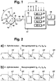
- FIG. 1 A first encoder disk of the exemplary embodiment is shown in FIG. 1, it is partially known from DE-OS 41 31 004, but the signal evaluation is carried out according to a different principle.
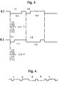
- Corresponding signal profiles are plotted in FIG. 2a, b, FIGS. 3a, b and FIG. 4 show signal profiles for a quick start sensor disk.
- FIG. 10 denotes a sensor disk which is connected to the camshaft 11 and rotates synchronously with it.
- Angle marks 12, 13, 14, 15 are arranged on the encoder disk 10, the angle marks 12, 13 and 14 being identical, while the angle mark 15 differs in a characteristic manner, for example in such a way that the angle which this angle mark encloses is smaller .
- This angle mark is also referred to as a reference mark or reference segment.
- segment S The distance between an edge of an angle mark and the same edge of the next angle mark is usually referred to as segment S.
- segment S In the illustrated in Figure 1 Embodiment, which is a 4-cylinder internal combustion engine, the angle or the length of the segment S is 90 °.
- the sensor disk shown in FIG. 1 is an example; in principle, it can also be connected to the crankshaft of the internal combustion engine. Since this turns twice as fast as the camshaft, the number of angle marks should be equal to half the number of cylinders in this case.
- the encoder disk 10, including its angle marks, is scanned with the aid of a pickup 16.
- the transducer 16 is, for example, a Hall sensor, it supplies an output signal S1 which, after being processed into a square-wave signal, reflects the surface structure of the sensor disk 10, the signal S1 being high when the angular marks pass the transducer 16 and are low during the remaining times.
- 2a, b show two different signal curves for S1, which are each obtained for 4-cylinder engines, the reference angle mark 15 and thus the reference angle segment being shorter and longer than the other angle marks. Otherwise, the TDC positions of the individual cylinders are also entered in FIG.
- the output signal S1 of the pickup 16 is evaluated in a microprocessor 17.
- This microprocessor can be, for example, the control unit of the internal combustion engine.
- the microprocessor 17 has further input variables, which are designated by 18 and, for example, the speed n, the intake manifold pressure p, a load signal L or a temperature, for example the engine temperature T, etc.
- microprocessor 17 contains a processing stage 19 and four memory cells SZ1, SZ2, SZ3, SZ4. If this number of memory cells corresponds to the number of angular marks or cylinders of the internal combustion engine, a time can be written into each memory cell.
- the microprocessor determines time intervals between individual edges of the signal S1, for example time intervals ti between dissimilar signal edges and time intervals Ti between identical signal edges. From these time intervals, the microprocessor determines the reference mark 15, which is assigned to a predeterminable cylinder, according to the method to be described below. From the recognition of the reference mark, the cylinder recognition can thus be carried out and, after the cylinder recognition has taken place, it is known that the positions of the other cylinders can also be determined, since all cylinders are in a fixed relationship to one another.
- the microprocessor 17 or the control unit of the internal combustion engine can trigger control pulses for the ignition and injection, the calculations being carried out in a conventional manner as a function of the other quantities supplied and, if appropriate, taking into account characteristic diagrams.
- sequential fuel injection, special ignition controls or knock control can be activated, for example.
- the detection of the reference mark 15 according to the invention and the associated cylinder detection is carried out by the microprocessor 17 as follows:
- the time periods ti are measured in each case and stored in a memory of the microprocessor 17.
- the time periods Ti which are also referred to as segment times, are recorded and likewise each written into a memory of the microprocessor.
- the times ti and Ti are assigned to each other so that they are mostly in the same combustion cycle. So that the influence of dynamics due to speed changes is reduced in the reference mark or cylinder recognition, the time periods ti are related to the time periods Ti; the ratio ti / Ti is thus formed. This ratio is normalized using the last ratio t (i -1) / T (i -1).
- a further value A is determined, which is added to the memory cells SZi arbitrarily assigned to the cylinders. After a certain course can be recognized in the memory cells SZi, the reference mark is recognized or the reference cylinder is identified.
- the value A is determined as a function of the value Xi in such a way that A can assume the value -1, 0 or +1, depending on how large the value of Xi is.
- the value A is added to the memory cells SZi assigned to the cylinders, the memory cells usually being set to zero at the start or reset.
- the memory cells are written in such a way that the next value is written into the next memory cell; their content changes from Zi to Zi + A, where A, as already mentioned, can take the values -1, 0 or +1.
- the ratio formation in the range of t2 gives a value which is greater or less than zero, depending on whether the time before the reference mark or the time after the reference mark is related to the corresponding total time.
- the value -1 is always written in a memory cell, while the value +1 is always entered in the next cell.
- the value zero is entered in the remaining memory cells.
- the value Xi can also be immediately compared with one or more suitable threshold values, and the reference mark and thus the relevant cylinder can be recognized on the basis of threshold value detections.
- a further possibility for reference mark and thus cylinder recognition is to compare several successive ratios Xi with one another and to recognize the reference mark, for example, when: X1 ⁇ X2 ⁇ X3, the values of X1 and X3 additionally being weighted with a selectable factor can, which should be matched to the existing angle mark lengths.
- a so-called quick start sensor disc can also represent an evaluation method in which two different, mutually identical segment lengths occur, these different segment lengths being shortened or lengthened compared to the lengths of the reference segments and z.
- a segment length is shortened compared to a reference segment and extended compared to the other reference segment. The two reference segments then either follow one another directly or are offset by 180 °.
- Such an encoder disk then leads to a signal curve as shown in FIG. 4 for a 4-cylinder internal combustion engine.
- crankshaft sensor If a defect in the crankshaft sensor is detected in an internal combustion engine with a crankshaft sensor and a camshaft sensor as described above, an emergency operation can take place in which the information that should actually be supplied by the crankshaft sensor is obtained from the information of a camshaft sensor.
Landscapes
- Engineering & Computer Science (AREA)
- Chemical & Material Sciences (AREA)
- Combustion & Propulsion (AREA)
- Physics & Mathematics (AREA)
- General Physics & Mathematics (AREA)
- Mechanical Engineering (AREA)
- General Engineering & Computer Science (AREA)
- Combined Controls Of Internal Combustion Engines (AREA)
- Measurement Of Length, Angles, Or The Like Using Electric Or Magnetic Means (AREA)
- Length Measuring Devices With Unspecified Measuring Means (AREA)
- Transmission And Conversion Of Sensor Element Output (AREA)
- Testing Of Engines (AREA)
Applications Claiming Priority (4)
| Application Number | Priority Date | Filing Date | Title |
|---|---|---|---|
| DE19623716 | 1996-06-14 | ||
| DE19623716 | 1996-06-14 | ||
| DE19639541 | 1996-09-26 | ||
| DE19639541A DE19639541A1 (de) | 1996-06-14 | 1996-09-26 | Einrichtung zur Zylindererkennung bei einer Mehrzylinder-Brennkraftmaschine |
Publications (3)
| Publication Number | Publication Date |
|---|---|
| EP0813050A2 true EP0813050A2 (fr) | 1997-12-17 |
| EP0813050A3 EP0813050A3 (fr) | 1999-01-13 |
| EP0813050B1 EP0813050B1 (fr) | 2004-06-30 |
Family
ID=26026564
Family Applications (1)
| Application Number | Title | Priority Date | Filing Date |
|---|---|---|---|
| EP97106221A Expired - Lifetime EP0813050B1 (fr) | 1996-06-14 | 1997-04-16 | Arrangement d'identification d'un cylindre dans un moteur à combustion avec plusieurs cylindres |
Country Status (2)
| Country | Link |
|---|---|
| EP (1) | EP0813050B1 (fr) |
| JP (1) | JP4154007B2 (fr) |
Cited By (4)
| Publication number | Priority date | Publication date | Assignee | Title |
|---|---|---|---|---|
| DE19929291A1 (de) * | 1999-06-25 | 2000-12-28 | Volkswagen Ag | Ottomotor mit halbsequentieller Kraftstoffeinspritzung |
| CN110043376A (zh) * | 2018-01-15 | 2019-07-23 | 罗伯特·博世有限公司 | 用于识别内燃机的起动方式的方法 |
| CN111601960A (zh) * | 2018-01-15 | 2020-08-28 | 罗伯特·博世有限公司 | 用于确定内燃机的位置的方法 |
| EP3653997A4 (fr) * | 2017-12-12 | 2020-09-16 | SZ DJI Technology Co., Ltd. | Procédé de détection de paramètre de rotation, codeur, radar laser et véhicule aérien sans pilote |
Family Cites Families (4)
| Publication number | Priority date | Publication date | Assignee | Title |
|---|---|---|---|---|
| GB8322886D0 (en) * | 1983-08-25 | 1983-09-28 | Lucas Ind Plc | Transducer means |
| DE4131004A1 (de) * | 1991-09-18 | 1993-03-25 | Bosch Gmbh Robert | Verfahren zur zylindererkennung |
| DE4141714C2 (de) * | 1991-12-18 | 2002-11-14 | Bosch Gmbh Robert | Steuersystem für eine Brennkraftmaschine |
| JP3336762B2 (ja) * | 1994-09-13 | 2002-10-21 | 三菱電機株式会社 | 内燃機関の気筒識別装置 |
-
1997
- 1997-04-16 EP EP97106221A patent/EP0813050B1/fr not_active Expired - Lifetime
- 1997-06-10 JP JP15193297A patent/JP4154007B2/ja not_active Expired - Fee Related
Cited By (6)
| Publication number | Priority date | Publication date | Assignee | Title |
|---|---|---|---|---|
| DE19929291A1 (de) * | 1999-06-25 | 2000-12-28 | Volkswagen Ag | Ottomotor mit halbsequentieller Kraftstoffeinspritzung |
| EP3653997A4 (fr) * | 2017-12-12 | 2020-09-16 | SZ DJI Technology Co., Ltd. | Procédé de détection de paramètre de rotation, codeur, radar laser et véhicule aérien sans pilote |
| US10859409B2 (en) | 2017-12-12 | 2020-12-08 | SZ DJI Technology Co., Ltd. | Rotation parameter detection method, encoder, laser radar and unmanned aerial vehicle |
| US11320290B2 (en) | 2017-12-12 | 2022-05-03 | SZ DJI Technology Co., Ltd. | Rotation parameter detection method, encoder, laser radar and unmanned aerial vehicle |
| CN110043376A (zh) * | 2018-01-15 | 2019-07-23 | 罗伯特·博世有限公司 | 用于识别内燃机的起动方式的方法 |
| CN111601960A (zh) * | 2018-01-15 | 2020-08-28 | 罗伯特·博世有限公司 | 用于确定内燃机的位置的方法 |
Also Published As
| Publication number | Publication date |
|---|---|
| EP0813050A3 (fr) | 1999-01-13 |
| EP0813050B1 (fr) | 2004-06-30 |
| JPH1073048A (ja) | 1998-03-17 |
| JP4154007B2 (ja) | 2008-09-24 |
Similar Documents
| Publication | Publication Date | Title |
|---|---|---|
| EP0572584B1 (fr) | Systeme de capteurs pour l'identification des cylindres dans un moteur a combustion interne | |
| DE4434833B4 (de) | Einrichtung zur Erkennung des Rückdrehens eines rotierenden Teiles einer Brennkraftmaschine | |
| EP0643803B1 (fr) | Agencement de capteurs permettant d'identifier rapidement un cylindre dans un moteur polycylindrique a combustion interne | |
| DE2951622C2 (fr) | ||
| EP0584566A2 (fr) | Procédé de détection du défaut dans l'analyse pour les signaux de sortie d'un détecteur de vitesse de rotation | |
| EP0862692A1 (fr) | Procede permettant de determiner l'angle de phase d'un moteur a combustion interne a quatre temps et a nombre impair de cylindres | |
| EP1045967B1 (fr) | Dispositif de reconnaissance de phase | |
| EP0831224B1 (fr) | Agencement de capteurs pour identifier rapidement un cylindre dans un moteur à combustion interne | |
| DE19609872A1 (de) | Vorrichtung zur Steuerung der Betriebsakte eines Verbrennungsmotors | |
| WO1993007449A1 (fr) | Agencement de detection de la position angulaire d'une piece rotative | |
| EP1070964B1 (fr) | Dispositif de reconnaissance de la rotation inverse d'une partie tournante d'un moteur à combustion interne | |
| DE102016200190A1 (de) | Verfahren und Funktionsüberwachungsvorrichtung zur Funktionsüberwachung einer Vorrichtung zur variablen Einstellung einer Zylinderverdichtung bei einem Hubkolben-Verbrennungsmotor | |
| DE4215938C2 (de) | Aussetzererkennungssystem bei einem Verbrennungsmotor | |
| EP0465614B1 (fr) | Procede pour la detection du temps moteur dans le cas d'un moteur a quatre temps | |
| DE102004024415B4 (de) | Fehlzündungserkennungssystem für eine Brennkraftmaschine | |
| WO1999007987A1 (fr) | Procede de determination de temps segmentaires | |
| WO2012139805A1 (fr) | Procédé pour déterminer une position initiale d'un mouvement cyclique | |
| DE3933147C2 (fr) | ||
| EP0813050A2 (fr) | Arrangement d'identification d'un cylindre dans un moteur à combustion avec plusieurs cylindres | |
| DE4418578B4 (de) | Einrichtung zur Erkennung der Phasenlage bei einer Brennkraftmaschine | |
| DE10159347B4 (de) | Steuervorrichtung und Steuerverfahren zur Steuerung einer Brennkraftmaschine | |
| DE19639541A1 (de) | Einrichtung zur Zylindererkennung bei einer Mehrzylinder-Brennkraftmaschine | |
| DE19821354A1 (de) | Vorrichtung oder Verfahren zur Unterdrückung und/oder Anzeige von Störungen | |
| DE10320046B4 (de) | Anordnung zur Bestimmung der Kurbelwellenlage einer mehrzylindrigen Brennkraftmaschine | |
| DE10246224A1 (de) | Vorrichtung und Verfahren zum Erkennen eines bestimmten Zylindersegments beim Start einer Brennkraftmaschine |
Legal Events
| Date | Code | Title | Description |
|---|---|---|---|
| PUAI | Public reference made under article 153(3) epc to a published international application that has entered the european phase |
Free format text: ORIGINAL CODE: 0009012 |
|
| AK | Designated contracting states |
Kind code of ref document: A2 Designated state(s): DE FR GB IT |
|
| PUAL | Search report despatched |
Free format text: ORIGINAL CODE: 0009013 |
|
| AK | Designated contracting states |
Kind code of ref document: A3 Designated state(s): DE FR GB IT |
|
| 17P | Request for examination filed |
Effective date: 19990713 |
|
| 17Q | First examination report despatched |
Effective date: 20020408 |
|
| GRAP | Despatch of communication of intention to grant a patent |
Free format text: ORIGINAL CODE: EPIDOSNIGR1 |
|
| GRAS | Grant fee paid |
Free format text: ORIGINAL CODE: EPIDOSNIGR3 |
|
| GRAA | (expected) grant |
Free format text: ORIGINAL CODE: 0009210 |
|
| AK | Designated contracting states |
Kind code of ref document: B1 Designated state(s): DE FR GB IT |
|
| REG | Reference to a national code |
Ref country code: GB Ref legal event code: FG4D Free format text: NOT ENGLISH |
|
| REF | Corresponds to: |
Ref document number: 59711744 Country of ref document: DE Date of ref document: 20040805 Kind code of ref document: P |
|
| GBT | Gb: translation of ep patent filed (gb section 77(6)(a)/1977) |
Effective date: 20041021 |
|
| ET | Fr: translation filed | ||
| PLBE | No opposition filed within time limit |
Free format text: ORIGINAL CODE: 0009261 |
|
| STAA | Information on the status of an ep patent application or granted ep patent |
Free format text: STATUS: NO OPPOSITION FILED WITHIN TIME LIMIT |
|
| 26N | No opposition filed |
Effective date: 20050331 |
|
| PGFP | Annual fee paid to national office [announced via postgrant information from national office to epo] |
Ref country code: FR Payment date: 20110427 Year of fee payment: 15 |
|
| PGFP | Annual fee paid to national office [announced via postgrant information from national office to epo] |
Ref country code: GB Payment date: 20110419 Year of fee payment: 15 |
|
| PGFP | Annual fee paid to national office [announced via postgrant information from national office to epo] |
Ref country code: IT Payment date: 20110427 Year of fee payment: 15 |
|
| PGFP | Annual fee paid to national office [announced via postgrant information from national office to epo] |
Ref country code: DE Payment date: 20110628 Year of fee payment: 15 |
|
| GBPC | Gb: european patent ceased through non-payment of renewal fee |
Effective date: 20120416 |
|
| REG | Reference to a national code |
Ref country code: FR Ref legal event code: ST Effective date: 20121228 |
|
| PG25 | Lapsed in a contracting state [announced via postgrant information from national office to epo] |
Ref country code: GB Free format text: LAPSE BECAUSE OF NON-PAYMENT OF DUE FEES Effective date: 20120416 |
|
| REG | Reference to a national code |
Ref country code: DE Ref legal event code: R119 Ref document number: 59711744 Country of ref document: DE Effective date: 20121101 |
|
| PG25 | Lapsed in a contracting state [announced via postgrant information from national office to epo] |
Ref country code: IT Free format text: LAPSE BECAUSE OF NON-PAYMENT OF DUE FEES Effective date: 20120416 Ref country code: FR Free format text: LAPSE BECAUSE OF NON-PAYMENT OF DUE FEES Effective date: 20120430 |
|
| PG25 | Lapsed in a contracting state [announced via postgrant information from national office to epo] |
Ref country code: DE Free format text: LAPSE BECAUSE OF NON-PAYMENT OF DUE FEES Effective date: 20121101 |