EP0813056A2 - Vorrichtung zur Durchführung von elektrochemischen Messungen - Google Patents
Vorrichtung zur Durchführung von elektrochemischen Messungen Download PDFInfo
- Publication number
- EP0813056A2 EP0813056A2 EP97106853A EP97106853A EP0813056A2 EP 0813056 A2 EP0813056 A2 EP 0813056A2 EP 97106853 A EP97106853 A EP 97106853A EP 97106853 A EP97106853 A EP 97106853A EP 0813056 A2 EP0813056 A2 EP 0813056A2
- Authority
- EP
- European Patent Office
- Prior art keywords
- measuring
- tube
- quartz glass
- glass tube
- electrode
- Prior art date
- Legal status (The legal status is an assumption and is not a legal conclusion. Google has not performed a legal analysis and makes no representation as to the accuracy of the status listed.)
- Granted
Links
Images


Classifications
-
- G—PHYSICS
- G01—MEASURING; TESTING
- G01N—INVESTIGATING OR ANALYSING MATERIALS BY DETERMINING THEIR CHEMICAL OR PHYSICAL PROPERTIES
- G01N33/00—Investigating or analysing materials by specific methods not covered by groups G01N1/00 - G01N31/00
- G01N33/38—Concrete; Lime; Mortar; Gypsum; Bricks; Ceramics; Glass
- G01N33/386—Glass
-
- G—PHYSICS
- G01—MEASURING; TESTING
- G01N—INVESTIGATING OR ANALYSING MATERIALS BY DETERMINING THEIR CHEMICAL OR PHYSICAL PROPERTIES
- G01N27/00—Investigating or analysing materials by the use of electric, electrochemical, or magnetic means
- G01N27/26—Investigating or analysing materials by the use of electric, electrochemical, or magnetic means by investigating electrochemical variables; by using electrolysis or electrophoresis
- G01N27/403—Cells and electrode assemblies
- G01N27/406—Cells and probes with solid electrolytes
- G01N27/407—Cells and probes with solid electrolytes for investigating or analysing gases
-
- G—PHYSICS
- G01—MEASURING; TESTING
- G01N—INVESTIGATING OR ANALYSING MATERIALS BY DETERMINING THEIR CHEMICAL OR PHYSICAL PROPERTIES
- G01N27/00—Investigating or analysing materials by the use of electric, electrochemical, or magnetic means
- G01N27/26—Investigating or analysing materials by the use of electric, electrochemical, or magnetic means by investigating electrochemical variables; by using electrolysis or electrophoresis
- G01N27/28—Electrolytic cell components
- G01N27/30—Electrodes, e.g. test electrodes; Half-cells
-
- G—PHYSICS
- G01—MEASURING; TESTING
- G01N—INVESTIGATING OR ANALYSING MATERIALS BY DETERMINING THEIR CHEMICAL OR PHYSICAL PROPERTIES
- G01N27/00—Investigating or analysing materials by the use of electric, electrochemical, or magnetic means
- G01N27/26—Investigating or analysing materials by the use of electric, electrochemical, or magnetic means by investigating electrochemical variables; by using electrolysis or electrophoresis
- G01N27/403—Cells and electrode assemblies
- G01N27/406—Cells and probes with solid electrolytes
- G01N27/411—Cells and probes with solid electrolytes for investigating or analysing of liquid metals
- G01N27/4115—Composition or fabrication of the electrodes and coatings thereon, e.g. catalysts
Definitions
- the invention relates to a device for carrying out electrochemical measurements in glass or salt melts with at least one measuring electrode and a reference electrode arrangement.
- the oxygen partial pressure is measured by means of an electrochemical measuring cell, also called a reference electrode arrangement, which is connected to a counter electrode (also measuring electrode) via a conventional display and / or evaluation device (measuring system).
- a platinum wire which is passed through an aluminum oxide body, is used as the measuring electrode. The platinum wire is exposed at the tip of the aluminum oxide body, so that it can come into contact with the melt as soon as the counter electrode is immersed in it.
- the aluminum oxide body is held in an aluminum oxide tube.
- oxygen penetrates from the atmosphere above the melt to the part of the measuring electrode that is in contact with the melt, so that the values measured there do not correspond to the actual conditions within the melt and the measurement is therefore subject to errors.
- the measuring electrode is made of platinum.
- the object of the present invention is to improve the measurement accuracy of, for example, oxygen partial pressure measurements in glass or salt melts, starting from the devices known from the prior art.
- the object is achieved in that the tip of the measuring electrode intended for immersion in the melt is formed from a noble metal and is sealed in a gas-tight manner in one end of a quartz glass tube, the measuring electrode being guided through the quartz glass tube (out of the melt to the evaluation device).
- a gas-tight holder means that no oxygen penetrates through the tube from the outside to the melt to be measured in such an amount that it influences the measurement.
- the noble metal is expediently a metal from the group iridium, platinum, palladium or rhodium or an alloy of at least one of these metals with at least one further noble metal (possibly also from this group). It is conceivable to use the device primarily for short-term measurements.
- connection between the measuring electrode and the quartz glass tube is sealed in a gas-tight manner at the end of the quartz glass tube intended for immersion in the melt.
- the quartz glass tube can be open towards the rear, out of the melt.
- the tip of the measuring electrode which is formed from precious metal, is connected within the quartz glass tube to a measuring wire which is preferably formed from molybdenum, tungsten or a chromium-nickel alloy (e.g. Cronix).
- a measuring wire which is preferably formed from molybdenum, tungsten or a chromium-nickel alloy (e.g. Cronix).
- the measuring wire is made of molybdenum or tungsten, it is possible to arrange a metal strip made of molybdenum between the tip of the measuring electrode formed from noble metal and the measuring wire.
- the connection between precious metal and measuring wire can in the Quartz glass tube must be melted down.
- a melted-in metal strip made of molybdenum ensures almost complete gas tightness.
- connection point is therefore preferably to be arranged behind the melting point in the quartz glass tube.
- a reference electrode is arranged in a solid electrolyte tube which is closed on one side, which is held with its end facing away from the closed end in a ceramic tube through which the reference electrode is guided and that the end of the reference electrode in the solid electrolyte tube by one Reference material is surrounded that is formed from a metal-metal oxide, preferably a nickel-nickel-oxide powder mixture; the reference electrode itself is expediently formed from a chromium-nickel alloy.
- the quartz glass tube and the ceramic tube are filled with corundum. Furthermore, it is advantageous that the quartz glass tube and the ceramic tube are held in a common carrier tube, which is preferably made of ceramic and which has a connector of the usual type at its end facing away from the immersion end for mechanical coupling and for connecting the measuring electrode and reference electrode to a measuring system .
- the carrier tube can be made of aluminum oxide and filled with spherical corundum.
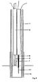
- the device shown in FIG. 1 has a carrier tube 1 which is formed from aluminum oxide. At its end facing away from the immersion end, a connecting piece 2 is arranged on the carrier tube 1, which is inserted into a holder, not shown in the figure, for example a metal lance.
- the wires passed through the carrier tube 1, the measuring wire 3 and the reference electrode 4 are connected via the connecting piece 2 to a measuring system, that is to say to a conventional display and / or evaluation unit.
- the measuring wire 3 and the reference electrode 4 are passed through quartz glass tubes 5 and embedded in spherical corundum 6.
- the reference electrode arrangement 7 and the quartz glass tube 8 are arranged at the end of the carrier tube 1 facing the immersion end of the device.
- the reference electrode arrangement 7 has a ceramic tube 9 made of aluminum oxide, through which the reference electrode 4 is led into the solid electrolyte tube 10.
- the solid electrolyte tube 10 made of zirconium oxide has in its interior as a reference material a nickel-nickel oxide powder mixture in which the reference electrode 4, which is formed from a chromium-nickel alloy (Cronix), is held.
- the measuring electrode with the measuring wire 3 is guided through the quartz glass tube 8, the tip 11 of the measuring electrode is formed from iridium wire.
- the iridium tip 11 extends into the quartz glass tube 8. The tip 11 is melted gas-tight in the end 12 of the quartz glass tube 8 over a distance of approximately 2 cm. Then the material of the measuring electrode changes. To save the relatively expensive iridium wire, the rest of the measuring electrode is a measuring wire 3 made of Cronix (a chromium-nickel alloy). Instead of Cronix, for example, molybdenum or tungsten can also be used as measuring wire 3.
- Cronix a chromium-nickel alloy
- FIG. 3 Another possibility of forming the measuring electrode is shown in FIG. 3.
- the tip 11 made of iridium is connected within the quartz glass tube 8 with a molybdenum strip 13, which is connected at its other end to the measuring wire 3.
- the measuring wire 3 can be formed, for example, from molybdenum or tungsten.
- the molybdenum strip 13 is completely melted into the end 12 of the quartz glass tube 8. This allows perfect gas tightness to be achieved.
- Quartz glass tube 8 and ceramic tube 9 are provided with a corundum filling, which stabilizes the position of the wires within the tubes.
- the device shown in Figure 4 is for voltametric measurement z.
- B. the iron, sulfur or chromium content in a glass melt. The procedure for this is described, for example, in "Glass Technical Reports” 68 (1995) No. 9, p. 273 ff.
- a measuring electrode and a reference electrode 4 are arranged in the support tube 1 made of aluminum oxide.
- the tip 11 of the measuring electrode is formed from iridium and melted into a quartz glass tube 8.
- the reference electrode 4 made of platinum is arranged in a ceramic tube 9, and a counter electrode 14 made of platinum is arranged at the immersion end of the carrier tube 1.
- the measurement with the described device enables very reliable results, primarily in short-term operation. Since the device can be manufactured very inexpensively, it can be designed as a disposable probe.
Landscapes
- Life Sciences & Earth Sciences (AREA)
- Chemical & Material Sciences (AREA)
- Health & Medical Sciences (AREA)
- Biochemistry (AREA)
- Physics & Mathematics (AREA)
- Analytical Chemistry (AREA)
- General Health & Medical Sciences (AREA)
- General Physics & Mathematics (AREA)
- Immunology (AREA)
- Pathology (AREA)
- Electrochemistry (AREA)
- Chemical Kinetics & Catalysis (AREA)
- Molecular Biology (AREA)
- Engineering & Computer Science (AREA)
- Medicinal Chemistry (AREA)
- Food Science & Technology (AREA)
- Ceramic Engineering (AREA)
- Measuring Oxygen Concentration In Cells (AREA)
- Secondary Cells (AREA)
- Hybrid Cells (AREA)
- Primary Cells (AREA)
- Investigating And Analyzing Materials By Characteristic Methods (AREA)
- Glass Compositions (AREA)
- Electrolytic Production Of Non-Metals, Compounds, Apparatuses Therefor (AREA)
- Battery Electrode And Active Subsutance (AREA)
- Investigating Or Analyzing Materials By The Use Of Electric Means (AREA)
Abstract
Description
- Die Erfindung betrifft eine Vorrichtung zur Durchführung von elektrochemischen Messungen in Glas- oder Salzschmelzen mit wenigstens einer Meßelektrode und einer Referenzelektrodenanordnung.
- Derartige Vorrichtungen sind vielfach, beispielsweise aus GB 2 057 695 A bekannt. Hier erfolgt eine Messung des Sauerstoffpartialdruckes mittels einer elektrochemischen Meßzelle, auch Referenzelektrodenanordnung genannt, die über eine übliche Anzeige- und/oder Auswerteeinrichtung (Meßsystem) mit einer Gegenelektrode (auch Meßelektrode) verbunden ist. Als Meßelektrode wird ein Platindraht verwendet, der durch einen Aluminiumoxid-Körper hindurchgeführt ist. An der Spitze des Aluminiumoxid-Körpers ist der Platindraht freiliegend, so daß er in Kontakt mit der Schmelze treten kann, sobald die Gegenelektrode in diese eintaucht. Der Aluminiumoxid-Körper ist in einem Aluminiumoxidrohr gehaltert. In der Praxis hat es sich gezeigt, daß es nicht möglich ist, eine gasdichte Durchführung zwischen der Platinelektrode und dem Aluminiumoxid-Körper zu schaffen. Dadurch dringt Sauerstoff aus der Atmosphäre oberhalb der Schmelze bis zu dem mit der Schmelze in Kontakt stehenden Teil der Meßelektrode, so daß die dort gemessenen Werte nicht den tatsächlichen Verhältnissen innerhalb der Schmelze entsprechen und die Messung dadurch fehlerbehaftet ist.
- Ähnliche Meßanordnungen sind beispielsweise auch aus DE 38 11 915 A1 bekannt. Auch hier ist die Meßelektrode aus Platin gebildet.
- Beispielsweise aus "Glastechnische Berichte" 68 (1995) No. 9, S. 273 ff. ist es bekannt, durch voltametrische Analyse mit drei Elektroden Eisen, Schwefel oder Chrom in Glasschmelzen zu bestimmen. Auch hier treten die genannten Probleme auf. So muß zum Beispiel die Größe der Elektrodenoberfläche im Glas genau bekannt sein.
- Aufgabe der vorliegenden Erfindung ist es, ausgehend von den aus dem Stand der Technik bekannten Vorrichtungen die Meßgenauigkeit von beispielsweise Sauerstoffpartialdruckmessungen in Glas- oder Salzschmelzen zu verbessern.
- Erfindungsgemäß wird die Aufgabe dadurch gelöst, daß die zum Eintauchen in die Schmelze bestimmte Spitze der Meßelektrode aus einem Edelmetall gebildet ist und in einem Ende eines Quarzglasrohr gasdicht eingeschmolzen ist, wobei die Meßelektrode durch das Quarzglasrohr hindurchgeführt ist (aus der Schmelze heraus zur Auswerteeinrichtung). Eine gasdichte Halterung bedeutet, daß kein Sauerstoff durch das Rohr von außen bis zur zu messenden Schmelze in einer solchen Menge dringt, die die Messung beeinflußt. Zweckmäßigerweise ist das Edelmetall ein Metall der Gruppe Iridium, Platin, Palladium oder Rhodium oder eine Legierung mindestens eines dieser Metalle mit mindestens einem weiteren Edelmetall (eventuell auch aus dieser Gruppe). Es ist denkbar, die Vorrichtung überwiegend für Kurzzeitmessungen einzusetzen.
- Zweckmäßig ist es, daß die Verbindung zwischen Meßelektrode und Quarzglasrohr an dem zum Eintauchen in die Schmelze bestimmten Ende des Quarzglasrohres gasdicht eingeschmolzen ist. Nach hinten, aus der Schmelze heraus, kann das Quarzglasrohr offen sein. Zweckmäßig ist es, daß die aus Edelmetall gebildete Spitze der Meßelektrode innerhalb des Quarzglasrohres mit einem Meßdraht verbunden ist, der vorzugsweise aus Molybdän, Wolfram oder einer Chrom-Nickel-Legierungen (z. B. Cronix) gebildet ist. Dadurch kann die Länge des als Elektrode verwendeten Edelmetall-Drahtes kurtgehalten werden, um Edelmetall einzusparen.
- Im Falle der Ausbildung des Meßdrahtes aus Molybdän oder Wolfram ist es möglich, zwischen der aus Edelmetall gebildeten Spitze der Meßelektrode und dem Meßdraht einen Metallstreifen aus Molybdän anzuordnen. Die Verbindung zwischen Edelmetall und Meßdraht kann in dem Quarzglasrohr eingeschmolzen sein. Insbesondere ein eingeschmolzener Metallstreifen aus Molybdän sichert eine nahezu absolute Gasdichtheit.
- Ein Chrom-Nickel-Draht kann nicht ohne weiteres in das Quarzglasrohr eingeschmolzen werden, da die Gefahr besteht, daß es bei der notwendigen Temperatur schmilzt. Die Verbindungsstelle ist daher vorzugsweise hinter der Einschmelzstelle in dem Quarzglasrohr anzuordnen.
- Vorteilhaft für eine hohe Meßgenauigkeit ist es, daß eine Referenzelektrode in einem einseitig geschlossenen Festelektrolytröhrchen angeordnet ist, das mit seinem dem geschlossenen Ende abgewandten Ende in einem Keramikrohr gehaltert ist, durch das die Referenzelektrode hindurchgeführt ist und daß das Ende der Referenzelektrode in dem Festelektrolytröhrchen von einem Referenzmaterial umgeben ist, daß aus einer Metall-Metalloxid-, vorzugsweise einer Nickel-Nickel-Oxid-Pulvermischung gebildet ist; die Referenzelektrode selbst ist zweckmäßigerweise aus einer Chrom-Nickel-Legierung gebildet.
- Zweckmäßig ist es weiterhin, daß das Quarzglasrohr und das Keramikrohr mit Korund gefüllt sind. Desweiteren ist es vorteilhaft, daß das Quarzglasrohr und das Keramikrohr in einem gemeinsamen Trägerrohr gehaltert sind, das vorzugsweise aus Keramik gebildet ist und das an seinem dem Eintauchende abgewandten Ende ein Verbindungsstück üblicher Art aufweist zur mechanischen Ankopplung und zur Verbindung von Meßelektrode und Referenzelektrode mit einem Meßsystem. Das Trägerrohr kann aus Aluminiumoxid gebildet und mit Kugelkorund gefüllt sein.
- Nachfolgend wird ein Ausführungsbeispiel der Erfindung anhand einer Zeichnung näher erläutert.
- In der Zeichnung zeigt
- Figur 1
- eine Darstellung der erfindungsgemäßen Vorrichtung,
- Figur 2
- einen Längsschnitt durch die erfindungsgemäße Vorrichtung,
- Figur 3
- einen Längsschnitt durch die in das Quarzglasrohr eingeschmolzene Meßelektrode und
- Figur 4
- einen Schnitt durch eine Vorrichtung mit drei Elektroden.
- Die in Figur 1 dargestellte Vorrichtung weist ein Trägerrohr 1 auf, das aus Aluminiumoxid gebildet ist. An seinem dem Eintauchende abgewandten Ende ist ein Verbindungsstück 2 an dem Trägerrohr 1 angeordnet, das in einen in der Figur nicht dargestellten Halter, beispielsweise eine metallene Lanze eingesteckt wird. Die durch das Trägerrohr 1 hindurchgeführten Drähte, der Meßdraht 3 und die Referenzelektrode 4 werden über das Verbindungsstück 2 mit einem Meßsystem, das heißt mit einer üblichen Anzeige- und/oder Auswerteeinheit verbunden. Innerhalb des Trägerrohres 1 sind der Meßdraht 3 und die Referenzelektrode 4 durch Quarzglasröhrchen 5 geführt und in Kugelkorund 6 eingebettet.
- An dem dem Eintauchende der Vorrichtung zugewandten Ende des Trägerrohres 1 sind die Referenzelektrodenanordnung 7 und das Quarzglasrohr 8 angeordnet. Die Referenzelektrodenanordnung 7 weist ein Keramikrohr 9 aus Aluminiumoxid auf, durch das die Referenzelektrode 4 bis in das Festelektrolytröhrchen 10 hineingeführt ist. Das Festelektrolytröhrchen 10 aus Zirkonoxid weist in seinem Inneren als Referenzmaterial eine Nickel-Nickeloxid-Pulvermischung auf, in der die Referenzelektrode 4, die aus einer Chrom-Nickel-Legierung (Cronix) gebildet ist, gehaltert ist. Durch das Quarzglasrohr 8 hindurch ist die Meßelektrode mit dem Meßdraht 3 geführt, die Spitze 11 der Meßelektrode ist aus Iridium-Draht gebildet. Sie kann jedoch auch aus Platin, Palladium, Rhodium oder einer Legierung, die überwiegend Iridium oder andere Metalle der vorgenannten Gruppe und darüber hinaus andere Edelmetalle enthält, gebildet sein. Die Spitze 11 aus Iridium ragt bis in das Quarzglasrohr 8 hinein. Die Spitze 11 ist in dem Ende 12 des Quarzglasrohres 8 gasdicht eingeschmolzen auf einer Strecke von etwa 2 cm. Danach wechselt das Material der Meßelektrode. Um den relativ teuren Iridium-Draht einzusparen, ist der Rest der Meßelektrode ein Meßdraht 3 aus Cronix (einer Chrom-Nickel-Legierung). Statt Cronix kann beispielsweise auch Molybdän oder Wolfram als Meßdraht 3 verwendet werden.
- Eine weitere Möglichkeit, die Meßelektrode auszubilden, ist in Figur 3 dargestellt. Hier ist die Spitze 11 aus Iridium innerhalb des Quarzglasrohres 8 mit einem Molybdän-Streifen 13 verbunden, der an seinem anderen Ende mit dem Meßdraht 3 verbunden ist. Der Meßdraht 3 kann in diesem Fall beispielsweise aus Molybdän oder Wolfram gebildet sein. Der Molybdänstreifen 13 ist in dem gezeigten Beispiel vollständig in das Ende 12 des Quarzglasrohres 8 eingeschmolzen. Dadurch kann eine perfekte Gasdichtheit erzielt werden.
- In den Figuren nicht dargestellt ist die Möglichkeit, den Molybdän-Streifen 13 aus dem zugeschmolzenen Ende 12 des Quarzglasrohres 8 herauszuführen und erst in dem offenen Rohr mit dem Meßdraht 3 zu verbinden. In einem solchen Fall wäre auch Cronix als Meßdraht 3 möglich.
- Quarzglasrohr 8 und Keramikrohr 9 sind mit einer Korundfüllung versehen, die die Lage der Drähte innerhalb der Rohre stabilisiert.
- Die in Figur 4 dargestellte Vorrichtung ist zur voltametrischen Messung z. B. des Eisen-, Schwefel- oder Chromgehaltes in einer Glasschmelze geeignet. Das Verfahren hierzu ist beispielsweise in "Glastechnische Berichte" 68 (1995) No. 9, S. 273 ff. beschrieben. In dem Trägerrohr 1 aus Alumiumoxid sind eine Meßelektrode und eine Referenzelektrode 4 angeordnet. Die Spitze 11 der Meßelektrode ist aus Iridium gebildet und in ein Quarzglasrohr 8 eingeschmolzen. Die Referenzelektrode 4 aus Platin ist in einem Keramikrohr 9 angeordnet, und an dem Eintauchende des Trägerrohres 1 ist eine Gegenelektrode 14 aus Platin angeordnet.
- Die Messung mit der beschriebenen Vorrichtung ermöglicht sehr zuverlässige Ergebnisse, in erster Linie im Kurzzeitbetrieb. Da die Vorrichtung sehr kostengünstig hergestellt werden kann, ist die Ausbildung als Einwegsonde möglich.
Claims (13)
- Vorrichtung zur Durchführung von elektrochemischen Messungen in Glas- oder Salzschmelzen mit wenigstens einer Meßelektrode und einer Referenzelektrodenanordnung, dadurch gekennzeichnet, daß die zum Eintauchen in die Schmelze bestimmte Spitze (11) der Meßelektrode aus einem Edelmetall gebildet ist und in einem Quarzglasrohr (8) eingeschmolzen ist, wobei die Meßelektrode durch das Quarzglasrohr (8) hindurchgeführt ist.
- Vorrichtung nach Anspruch 1, dadurch gekennzeichnet, daß das Edelmetall ein Metall der Gruppe Iridium, Platin, Palladium oder Rhodium oder eine Legierung mindestens eines dieser Metalle mit mindestens einem weiteren Edelmetall ist.
- Vorrichtung nach Anspruch 1 oder 2, dadurch gekennzeichnet, daß die Verbindung zwischen Meßelektrode und Quarzglasrohr (8) an dem zum Eintauchen in die Schmelze bestimmten Ende (12) des Quarzglasrohres (8) eingeschmolzen ist.
- Vorrichtung nach einem der Ansprüche 1 bis 3, dadurch gekennzeichnet, daß die aus Edelmetall gebildete Spitze (11) der Meßelektrode innerhalb des Quarzglasrohres (8) mit einem Meßdraht (3) verbunden ist.
- Vorrichtung nach Anspruch 4, dadurch gekennzeichnet, daß zwischen der aus Edelmetall gebildeten Spitze (11) der Meßelektrode und dem Meßdraht (3) ein Metallstreifen (13) aus Molybdän angeordnet ist.
- Vorrichtung nach Anspruch 5, dadurch gekennzeichnet, daß der Meßdraht (3) aus Molybdän oder Wolfram gebildet ist.
- Vorrichtung nach einem der Ansprüche 4 bis 6, dadurch gekennzeichnet, daß die Verbindung zwischen Edelmetall und dem Meßdraht (3) in dem Quarzglasrohr (8) eingeschmolzen ist.
- Vorrichtung nach Anspruch 4, dadurch gekennzeichnet, daß der Meßdraht (3) aus einer Chrom-Nickel-Legierung gebildet ist.
- Vorrichtung nach einem der Ansprüche 1 bis 8, dadurch gekennzeichnet, daß eine Referenzelektrode (4) in einem einseitig geschlossenen Festelektrolytröhrchen angeordnet ist, das mit seinem dem geschlossenen Ende gegenüberliegenden Ende in einem Keramikrohr (9) gehaltert ist, durch das die Referenzelektrode (4) hindurchgeführt ist und daß das Ende der Referenzelektrode (4) in dem Festelektrolytröhrchen (10) von einem Referenzmaterial umgeben ist, das aus einer Metall-Metalloxid-, vorzugsweise einer Nickel-Nickeloxid-Pulvermischung gebildet ist.
- Vorrichtung nach einem der Ansprüche 1 bis 9, dadurch gekennzeichnet, daß die Referenzelektrode (4) aus einer Chrom-Nickel-Legierung gebildet ist.
- Vorrichtung nach Anspruch 9 oder 10, dadurch gekennzeichnet, daß das Quarzglasrohr (8) und das Keramikrohr (9) mit Korund gefüllt sind.
- Vorrichtung nach einem der Ansprüche 9 bis 11, dadurch gekennzeichnet, daß das Quarzglasrohr (8) und und das Keramikrohr (9) in einem gemeinsamen Trägerrohr (1) gehaltert sind, das vorzugsweise aus Keramik gebildet ist und das an seinem dem Eintauchende abgewandten Ende ein Verbindungsstück (2) aufweist zur mechanischen Ankopplung und zur Verbindung von Meßelektrode und Referenzelektrode (4) mit einem Meßsystem.
- Vorrichtung nach Anspruch 12, dadurch gekennzeichnet, daß das Trägerrohr (1) aus Aluminiumoxid gebildet ist und daß es mit Kugelkorund gefüllt ist.
Applications Claiming Priority (2)
| Application Number | Priority Date | Filing Date | Title |
|---|---|---|---|
| DE19623687A DE19623687C1 (de) | 1996-06-14 | 1996-06-14 | Vorrichtung zur Durchführung von elektrochemischen Messungen |
| DE19623687 | 1996-06-14 |
Publications (3)
| Publication Number | Publication Date |
|---|---|
| EP0813056A2 true EP0813056A2 (de) | 1997-12-17 |
| EP0813056A3 EP0813056A3 (de) | 1998-07-15 |
| EP0813056B1 EP0813056B1 (de) | 2008-12-24 |
Family
ID=7796901
Family Applications (1)
| Application Number | Title | Priority Date | Filing Date |
|---|---|---|---|
| EP97106853A Expired - Lifetime EP0813056B1 (de) | 1996-06-14 | 1997-04-25 | Vorrichtung zur Durchführung von elektrochemischen Messungen in Glas- oder Salzschmelzen |
Country Status (14)
| Country | Link |
|---|---|
| EP (1) | EP0813056B1 (de) |
| JP (1) | JPH1062381A (de) |
| KR (1) | KR100484707B1 (de) |
| CN (1) | CN1114829C (de) |
| AT (1) | ATE418727T1 (de) |
| AU (1) | AU2487697A (de) |
| BR (1) | BR9703584A (de) |
| CZ (1) | CZ179197A3 (de) |
| DE (2) | DE19623687C1 (de) |
| DK (1) | DK0813056T3 (de) |
| ES (1) | ES2320282T3 (de) |
| PL (1) | PL184528B1 (de) |
| PT (1) | PT813056E (de) |
| TR (1) | TR199700501A3 (de) |
Families Citing this family (1)
| Publication number | Priority date | Publication date | Assignee | Title |
|---|---|---|---|---|
| CN103852507A (zh) * | 2012-11-30 | 2014-06-11 | 汪林林 | 可带压力插拔的测量装置 |
Family Cites Families (11)
| Publication number | Priority date | Publication date | Assignee | Title |
|---|---|---|---|---|
| GB1277751A (en) * | 1969-04-17 | 1972-06-14 | Pilkington Brothers Ltd | Method of and apparatus for removing dissolved oxygen from molten tin |
| FR2122758A6 (en) * | 1971-01-22 | 1972-09-01 | Siderurgie Fse Inst Rech | Solid electrolyte electrochemical cell - with a molybdenum wire reference couple |
| FR2469709A1 (fr) * | 1979-08-31 | 1981-05-22 | Unisearch Ltd | Procede et appareil de mesure du potentiel d'oxydo-reduction de masses fondues a conductibilite ionique |
| US4313799A (en) * | 1980-04-04 | 1982-02-02 | Owens-Corning Fiberglas Corporation | Oxygen sensor and method for determining the oxygen activity in molten glass |
| DE3028270C2 (de) * | 1980-07-25 | 1986-08-14 | Schott Glaswerke, 6500 Mainz | Meßanordnung zur Messung von Sauerstoff-Partialdrücken |
| DE3109454A1 (de) * | 1981-03-12 | 1982-09-23 | Schott Glaswerke | Sonde zur messung von sauerstoffpartialdruecken in hochaggressiven medien |
| JPS58139060A (ja) * | 1982-02-05 | 1983-08-18 | リ−ズ・アンド・ノ−スラツプ・カンパニ− | 高速感応性酸素セル |
| DE3709196A1 (de) * | 1986-03-27 | 1987-10-01 | Wissenschaftlich Tech Betrieb | Sauerstoffmesssonde fuer hohe temperaturen |
| DE3811865C1 (en) * | 1988-04-09 | 1989-05-24 | Schott Glaswerke, 6500 Mainz, De | Measurement device for measuring the oxygen partial pressure in aggressive liquids at high temperature |
| DE3811864A1 (de) * | 1988-04-09 | 1989-10-19 | Schott Glaswerke | Messvorrichtung zum messen des sauerstoffpartialdruckes in aggressiven fluessigkeiten hoher temperatur |
| DE3811915A1 (de) * | 1988-04-09 | 1989-10-19 | Schott Glaswerke | Messvorrichtung zum messen des sauerstoffpartialdruckes in aggressiven fluessigkeiten hoher temperatur |
-
1996
- 1996-06-14 DE DE19623687A patent/DE19623687C1/de not_active Expired - Fee Related
-
1997
- 1997-04-25 DK DK97106853T patent/DK0813056T3/da active
- 1997-04-25 EP EP97106853A patent/EP0813056B1/de not_active Expired - Lifetime
- 1997-04-25 PT PT97106853T patent/PT813056E/pt unknown
- 1997-04-25 DE DE59712989T patent/DE59712989D1/de not_active Expired - Lifetime
- 1997-04-25 ES ES97106853T patent/ES2320282T3/es not_active Expired - Lifetime
- 1997-04-25 AT AT97106853T patent/ATE418727T1/de active
- 1997-06-02 JP JP9157344A patent/JPH1062381A/ja not_active Withdrawn
- 1997-06-10 PL PL97320467A patent/PL184528B1/pl not_active IP Right Cessation
- 1997-06-11 KR KR1019970024071A patent/KR100484707B1/ko not_active Expired - Fee Related
- 1997-06-11 CZ CZ971791A patent/CZ179197A3/cs unknown
- 1997-06-13 TR TR97/00501A patent/TR199700501A3/tr unknown
- 1997-06-13 CN CN97112719A patent/CN1114829C/zh not_active Expired - Lifetime
- 1997-06-13 AU AU24876/97A patent/AU2487697A/en not_active Abandoned
- 1997-06-16 BR BR9703584A patent/BR9703584A/pt not_active Application Discontinuation
Also Published As
| Publication number | Publication date |
|---|---|
| PT813056E (pt) | 2009-03-31 |
| CN1168974A (zh) | 1997-12-31 |
| DE59712989D1 (de) | 2009-02-05 |
| EP0813056B1 (de) | 2008-12-24 |
| TR199700501A2 (xx) | 1998-01-21 |
| KR100484707B1 (ko) | 2005-08-17 |
| EP0813056A3 (de) | 1998-07-15 |
| PL320467A1 (en) | 1997-12-22 |
| CN1114829C (zh) | 2003-07-16 |
| PL184528B1 (pl) | 2002-11-29 |
| BR9703584A (pt) | 1998-11-03 |
| ES2320282T3 (es) | 2009-05-20 |
| AU2487697A (en) | 1997-12-18 |
| CZ179197A3 (cs) | 1998-01-14 |
| TR199700501A3 (tr) | 1998-01-21 |
| ATE418727T1 (de) | 2009-01-15 |
| DK0813056T3 (da) | 2009-04-27 |
| DE19623687C1 (de) | 1997-10-16 |
| JPH1062381A (ja) | 1998-03-06 |
| KR980003574A (ko) | 1998-03-30 |
Similar Documents
| Publication | Publication Date | Title |
|---|---|---|
| DE1288815B (de) | Bezugselektrodenanordnung | |
| DE1808584A1 (de) | Elektrochemische Zelle | |
| DE2057962C3 (de) | ||
| DE1228080B (de) | Vorrichtung zum Messen des pH-Wertes von Substanzen des lebenden Koerpers | |
| EP0813057B1 (de) | Vorrichtung zur Durchführung von elektrochemischen Messungen in Glas- oder Salzschmelzen | |
| EP0416336A2 (de) | Temperaturwächter | |
| EP0813056B1 (de) | Vorrichtung zur Durchführung von elektrochemischen Messungen in Glas- oder Salzschmelzen | |
| DE3035608C2 (de) | ||
| DE3027863A1 (de) | Flammenionisationsdetektor | |
| DE2332606A1 (de) | Kombinationselektrode | |
| CH501919A (de) | Glaselektrode zum Messen von Ionenkonzentrationen | |
| DE3028270C2 (de) | Meßanordnung zur Messung von Sauerstoff-Partialdrücken | |
| DE2632249A1 (de) | Elektrochemischer messfuehler | |
| DE102005019665B3 (de) | Eintauchmesssonde, insbesondere Einwurfmesssonde | |
| DE1928845B2 (de) | Vorrichtung zur unmittelbaren Messung des Sauerstoffgehaltes von Metallschmelzen | |
| DE2934244C2 (de) | Meßzelle | |
| DE2141164A1 (de) | Vorrichtung zum Messen der Konzentration des in flüssigen Metallen aufgelösten Sauerstoffs | |
| DE2558092C2 (de) | Keramikform zur Entnahme einer Probe aus einem blasenden Stahl-Konverter | |
| DE3118447A1 (de) | Sauerstoffmesssonde, insbesondere zum erfassen des sauerstoffgehaltes einer kohlenstoffhaltigen atmosphaere | |
| DE4438524C2 (de) | pH-Doppelmeßkette | |
| DE2057201A1 (de) | Vorrichtung zur Bestimmung des Sauerstoffpotentials von Gasen bei hohen Temperaturen | |
| EP1037042B1 (de) | Eintauchsensor, Messanordnung und Messverfahren zur Uberwachung von Aluminium-Elektrolysezellen | |
| DE8224553U1 (de) | Sauerstoffmesssonde | |
| DE859540C (de) | Messdrahtsystem mit temperaturempfindlicher Wicklung, insbesondere fuer gasanalytische Messungen | |
| DE1573158A1 (de) | Thermoelement-Aggregat |
Legal Events
| Date | Code | Title | Description |
|---|---|---|---|
| PUAI | Public reference made under article 153(3) epc to a published international application that has entered the european phase |
Free format text: ORIGINAL CODE: 0009012 |
|
| 17P | Request for examination filed |
Effective date: 19970507 |
|
| AK | Designated contracting states |
Kind code of ref document: A2 Designated state(s): AT BE DE DK ES FI FR GB GR IE IT LU NL PT SE |
|
| PUAL | Search report despatched |
Free format text: ORIGINAL CODE: 0009013 |
|
| AK | Designated contracting states |
Kind code of ref document: A3 Designated state(s): AT BE DE DK ES FI FR GB GR IE IT LU NL PT SE |
|
| GRAP | Despatch of communication of intention to grant a patent |
Free format text: ORIGINAL CODE: EPIDOSNIGR1 |
|
| RTI1 | Title (correction) |
Free format text: DEVICE FOR CARRYING OUT ELECTROCHEMICAL MEASUREMENTS IN GLASS OR SALT MELTS |
|
| GRAS | Grant fee paid |
Free format text: ORIGINAL CODE: EPIDOSNIGR3 |
|
| GRAA | (expected) grant |
Free format text: ORIGINAL CODE: 0009210 |
|
| AK | Designated contracting states |
Kind code of ref document: B1 Designated state(s): AT BE DE DK ES FI FR GB GR IE IT LU NL PT SE |
|
| REG | Reference to a national code |
Ref country code: GB Ref legal event code: FG4D Free format text: NOT ENGLISH |
|
| REG | Reference to a national code |
Ref country code: IE Ref legal event code: FG4D Free format text: LANGUAGE OF EP DOCUMENT: GERMAN |
|
| REF | Corresponds to: |
Ref document number: 59712989 Country of ref document: DE Date of ref document: 20090205 Kind code of ref document: P |
|
| REG | Reference to a national code |
Ref country code: PT Ref legal event code: SC4A Free format text: AVAILABILITY OF NATIONAL TRANSLATION Effective date: 20090323 |
|
| REG | Reference to a national code |
Ref country code: GR Ref legal event code: EP Ref document number: 20090400890 Country of ref document: GR |
|
| REG | Reference to a national code |
Ref country code: SE Ref legal event code: TRGR |
|
| REG | Reference to a national code |
Ref country code: DK Ref legal event code: T3 |
|
| REG | Reference to a national code |
Ref country code: ES Ref legal event code: FG2A Ref document number: 2320282 Country of ref document: ES Kind code of ref document: T3 |
|
| PLBE | No opposition filed within time limit |
Free format text: ORIGINAL CODE: 0009261 |
|
| STAA | Information on the status of an ep patent application or granted ep patent |
Free format text: STATUS: NO OPPOSITION FILED WITHIN TIME LIMIT |
|
| 26N | No opposition filed |
Effective date: 20090925 |
|
| PGFP | Annual fee paid to national office [announced via postgrant information from national office to epo] |
Ref country code: ES Payment date: 20120425 Year of fee payment: 16 |
|
| PGFP | Annual fee paid to national office [announced via postgrant information from national office to epo] |
Ref country code: AT Payment date: 20120411 Year of fee payment: 16 |
|
| PGFP | Annual fee paid to national office [announced via postgrant information from national office to epo] |
Ref country code: LU Payment date: 20130419 Year of fee payment: 17 |
|
| PGFP | Annual fee paid to national office [announced via postgrant information from national office to epo] |
Ref country code: IE Payment date: 20130422 Year of fee payment: 17 Ref country code: DK Payment date: 20130418 Year of fee payment: 17 Ref country code: GB Payment date: 20130418 Year of fee payment: 17 Ref country code: DE Payment date: 20130419 Year of fee payment: 17 Ref country code: SE Payment date: 20130418 Year of fee payment: 17 Ref country code: BE Payment date: 20130418 Year of fee payment: 17 |
|
| PGFP | Annual fee paid to national office [announced via postgrant information from national office to epo] |
Ref country code: FI Payment date: 20130411 Year of fee payment: 17 Ref country code: FR Payment date: 20130515 Year of fee payment: 17 Ref country code: GR Payment date: 20130419 Year of fee payment: 17 Ref country code: IT Payment date: 20130423 Year of fee payment: 17 Ref country code: PT Payment date: 20130424 Year of fee payment: 17 Ref country code: NL Payment date: 20130418 Year of fee payment: 17 |
|
| REG | Reference to a national code |
Ref country code: DE Ref legal event code: R119 Ref document number: 59712989 Country of ref document: DE |
|
| REG | Reference to a national code |
Ref country code: PT Ref legal event code: MM4A Free format text: LAPSE DUE TO NON-PAYMENT OF FEES Effective date: 20141027 |
|
| REG | Reference to a national code |
Ref country code: DK Ref legal event code: EBP Effective date: 20140430 |
|
| REG | Reference to a national code |
Ref country code: NL Ref legal event code: V1 Effective date: 20141101 |
|
| PG25 | Lapsed in a contracting state [announced via postgrant information from national office to epo] |
Ref country code: LU Free format text: LAPSE BECAUSE OF NON-PAYMENT OF DUE FEES Effective date: 20140425 |
|
| REG | Reference to a national code |
Ref country code: SE Ref legal event code: EUG |
|
| REG | Reference to a national code |
Ref country code: AT Ref legal event code: MM01 Ref document number: 418727 Country of ref document: AT Kind code of ref document: T Effective date: 20140425 |
|
| GBPC | Gb: european patent ceased through non-payment of renewal fee |
Effective date: 20140425 |
|
| REG | Reference to a national code |
Ref country code: GR Ref legal event code: ML Ref document number: 20090400890 Country of ref document: GR Effective date: 20141104 |
|
| REG | Reference to a national code |
Ref country code: FR Ref legal event code: ST Effective date: 20141231 |
|
| REG | Reference to a national code |
Ref country code: IE Ref legal event code: MM4A |
|
| PG25 | Lapsed in a contracting state [announced via postgrant information from national office to epo] |
Ref country code: GR Free format text: LAPSE BECAUSE OF NON-PAYMENT OF DUE FEES Effective date: 20141104 Ref country code: PT Free format text: LAPSE BECAUSE OF NON-PAYMENT OF DUE FEES Effective date: 20141027 Ref country code: GB Free format text: LAPSE BECAUSE OF NON-PAYMENT OF DUE FEES Effective date: 20140425 Ref country code: FI Free format text: LAPSE BECAUSE OF NON-PAYMENT OF DUE FEES Effective date: 20140425 Ref country code: DE Free format text: LAPSE BECAUSE OF NON-PAYMENT OF DUE FEES Effective date: 20141101 Ref country code: SE Free format text: LAPSE BECAUSE OF NON-PAYMENT OF DUE FEES Effective date: 20140426 |
|
| REG | Reference to a national code |
Ref country code: DE Ref legal event code: R119 Ref document number: 59712989 Country of ref document: DE Effective date: 20141101 |
|
| PG25 | Lapsed in a contracting state [announced via postgrant information from national office to epo] |
Ref country code: FR Free format text: LAPSE BECAUSE OF NON-PAYMENT OF DUE FEES Effective date: 20140430 Ref country code: NL Free format text: LAPSE BECAUSE OF NON-PAYMENT OF DUE FEES Effective date: 20141101 Ref country code: AT Free format text: LAPSE BECAUSE OF NON-PAYMENT OF DUE FEES Effective date: 20140425 |
|
| PG25 | Lapsed in a contracting state [announced via postgrant information from national office to epo] |
Ref country code: IT Free format text: LAPSE BECAUSE OF NON-PAYMENT OF DUE FEES Effective date: 20140425 |
|
| PG25 | Lapsed in a contracting state [announced via postgrant information from national office to epo] |
Ref country code: IE Free format text: LAPSE BECAUSE OF NON-PAYMENT OF DUE FEES Effective date: 20140425 Ref country code: DK Free format text: LAPSE BECAUSE OF NON-PAYMENT OF DUE FEES Effective date: 20140430 |
|
| REG | Reference to a national code |
Ref country code: ES Ref legal event code: FD2A Effective date: 20150526 |
|
| PG25 | Lapsed in a contracting state [announced via postgrant information from national office to epo] |
Ref country code: ES Free format text: LAPSE BECAUSE OF NON-PAYMENT OF DUE FEES Effective date: 20140426 |
|
| PG25 | Lapsed in a contracting state [announced via postgrant information from national office to epo] |
Ref country code: BE Free format text: LAPSE BECAUSE OF NON-PAYMENT OF DUE FEES Effective date: 20140430 |