EP0813909A2 - Buse d'atomisation pneumatique de liquide avec mélange interne - Google Patents
Buse d'atomisation pneumatique de liquide avec mélange interne Download PDFInfo
- Publication number
- EP0813909A2 EP0813909A2 EP97420094A EP97420094A EP0813909A2 EP 0813909 A2 EP0813909 A2 EP 0813909A2 EP 97420094 A EP97420094 A EP 97420094A EP 97420094 A EP97420094 A EP 97420094A EP 0813909 A2 EP0813909 A2 EP 0813909A2
- Authority
- EP
- European Patent Office
- Prior art keywords
- spray
- air
- nozzle
- mixing chamber
- set forth
- Prior art date
- Legal status (The legal status is an assumption and is not a legal conclusion. Google has not performed a legal analysis and makes no representation as to the accuracy of the status listed.)
- Withdrawn
Links
Images

Classifications
-
- B—PERFORMING OPERATIONS; TRANSPORTING
- B05—SPRAYING OR ATOMISING IN GENERAL; APPLYING FLUENT MATERIALS TO SURFACES, IN GENERAL
- B05B—SPRAYING APPARATUS; ATOMISING APPARATUS; NOZZLES
- B05B7/00—Spraying apparatus for discharge of liquids or other fluent materials from two or more sources, e.g. of liquid and air, of powder and gas
- B05B7/02—Spray pistols; Apparatus for discharge
- B05B7/04—Spray pistols; Apparatus for discharge with arrangements for mixing liquids or other fluent materials before discharge
- B05B7/0416—Spray pistols; Apparatus for discharge with arrangements for mixing liquids or other fluent materials before discharge with arrangements for mixing one gas and one liquid
- B05B7/0483—Spray pistols; Apparatus for discharge with arrangements for mixing liquids or other fluent materials before discharge with arrangements for mixing one gas and one liquid with gas and liquid jets intersecting in the mixing chamber
Definitions
- the present invention relates to spray nozzles, particularly internal mix air spray nozzles, for spraying fluent materials.
- fluid material spraying apparatus commonly known as "spray guns".
- air spray gun wherein fluid material is atomized into a spray by interaction with compressed air.
- air spray guns There are in turn two principal types of air spray guns, namely, the external mix type wherein compressed air interacts with the fluid material externally of the spray gun, e.g., forwardly of the spray nozzle of the gun, and the internal mix type wherein the compressed air is interacted with the fluid material within the spray nozzle of the gun for atomization upon exit of the mixture from the gun nozzle.
- the internal mix air spray nozzle is well suited for spraying fluid materials covering a wide range of viscosities, from low viscosity paints and stains to heavily filled and viscous materials, especially difficult to spray materials having a high particulate content.
- the present invention was developed in conjunction with the development of a spray gun for spraying materials which have a high viscosity and/or a high concentration of fibrous and/or abrasive particles, especially particulate loaded mortar, such as plaster or conventional stucco, or the synthetic stuccos used in exterior insulation finish systems, known as E.I.F.S.
- a spray gun for spraying materials which have a high viscosity and/or a high concentration of fibrous and/or abrasive particles, especially particulate loaded mortar, such as plaster or conventional stucco, or the synthetic stuccos used in exterior insulation finish systems, known as E.I.F.S.
- the objective of the present development was to provide an internal mix air spray nozzle that would be easier to use and that would do a more effective job of discharging from the nozzle an atomized spray of fluent material having a uniform spray density for application, for example, to the exterior surface of a building for providing a durable and attractive exterior finish on the building.
- the present invention provides a new and improved internal mix air spray nozzle for spraying fluent materials of all viscosities, and especially heavily filled and viscous materials such, for example, as stucco.
- a prime feature of the invention resides in the development of an internal mix nozzle which, in contrast to conventional designs, does not develop a back pressure within the nozzle but instead develops a vacuum or suction force which assists in feeding the fluid material, especially heavily laden materials, into and through the nozzle.
- Another feature resides in circumferential, more or less tangential, delivery of compressed air directly into an air and fluid mixing chamber through a plurality of forwardly directed circumferentially spaced ports in the peripheral wall of the chamber to aid in development of the material feeding or suction force, to insure thorough and uniform mixing of the air and the fluid material, and to cause a thoroughly atomized spray of fluid material of uniform spray density to be emitted form the nozzle.
- Another aspect of the invention resides in the establishment of particular relationships between the port areas and operating pressures of the air and fluid to insure attainment of the above stated objects and advantages.
- a further feature of the invention resides in the development of a unitary, one piece internal mix air spray nozzle which consolidates the three component assembly of the prior art into a single piece part.
- Another objective is to provide an improved internal mix air spray nozzle that is very economical to produce and that accommodates generous tolerances in the manufacturing process.
- a spray gun 10 for spraying fluent materials which have a high concentration of particulate components.
- the spray gun 10 includes a barrel 12, a handle 14, a fluid material valve 31, an air valve 70, and two inlets 27 and 45, one 27 for pressurized air and the other 45 fbr fluent material to be sprayed.
- the spray gun illustrated is described in greater detail in US patent application Serial No. 08/407,320, filed March 20, 1995.
- the spray gun operates by mixing fluent material at a first pressure with air pressurized at a second, preferably higher, pressure to atomize the liquid in the spray material before discharging the mixture.
- the spray valve 31, located in the barrel 12, controls the flow of the fluid materials.
- the air valve 70, located in the handle 14, controls the flow of pressurized air.
- the spray valve 31 cooperates with the air valve 70 so that when the air valve is in the open position the spray valve is also in the open position, and when the air valve is in the closed position the spray valve is also in the closed position.
- the fluent spray material is typically under approximately 25 to 50 psi of pressure, so that when the spray valve 31 is open, the spray material flows through the spray material inlet 45 into a valve chamber 40 wherein it is mixed with a first supply of pressurized air. The spray material then flows into the spray nozzle 50, where a second supply of pressurized air is added to atomize the liquid in the spray material before the mixture is discharged from the spray gun 10.
- the spray valve 31 comprises the valve chamber 40 and a valve element 32.
- the valve chamber has an interior wall, and is preferably shaped so that the interior wall defines an elongated cylindrical bore.
- the valve chamber has an inlet for pressurized air, an inlet for spray material, and an outlet for the mixture.
- the air inlet is a spray valve passage 80 that enters at the rear end of the valve chamber, allowing pressurized air into the valve chamber 40. From there, the pressurized air flows through a conduit 33 in the valve element 32 to the front of the valve chamber.
- the spray material port 45 enters an intermediate portion of the valve chamber, allowing spray material to flow into the valve chamber. The spray material mixes with the pressurized air and flows out of the valve chamber through the outlet 46 into the nozzle 50,
- valve element 32 is slidably displaceable between an open position and a closed position.
- the valve element 32 has a front cylindrically-shaped body portion 36 and a valve stem 38 projecting from the rear, which preferably has a smaller diameter than the valve body portion.
- a conduit 33 passes through the valve element 32 so that pressurized air can flow from the spray valve passage 80 through the valve element into the front of the valve chamber.
- the front portion of the conduit 33 is coaxial with the valve body 36, and opens to the front of the valve element,
- the rear portion of the conduit preferably angles toward the outer edge of the valve element so that the conduit opens to the rear of the valve body 36 into an annular space surrounding the valve element within the valve chamber 40.
- the clearance between the outside diameter of the valve body 36 and the valve chamber bore must fall between two limits.
- the sliding clearance must be greater than zero, i.e., the diameter of the valve body must be smaller than the valve chamber bore.
- the upper limit of the sliding clearance is dictated by the size of the particles in the spray material.
- the sliding clearance should be no greater than the size of the average particle in the spray material, so that it impedes passage of the particles through the sliding clearance space between the valve body 36 and the valve chamber 40.
- the particles that cannot pass through the sliding clearance space agglomerate around the spray material port 45 when the spray valve 31 is closed.
- This agglomeration of particles forms a seal preventing the liquid in the spray material from leaking through the sliding clearance space into the valve chamber 40 when the spray valve 31 is closed.
- Such a seal allows the nozzle 50 to be removed and cleaned or replaced while the spray material is under pressure with little or no leakage.
- the sliding clearance space should be reduced.
- the sliding clearance falls within a range that prevents passage of spray materials having a viscosity equal to or greater than elastomeric paint, which typically has a viscosity between 3 and 6 poise.
- the maximum sliding clearance to prevent leakage is 0.0075.
- the sliding clearance is approximately 0.00075 inch.
- the nozzle By reducing the sliding clearance to this limit range, the nozzle can be removed without causing leakage even when using spray material without a significant particulate content. Without the reduced sliding clearance, a resilient seal between the valve body and the valve chamber would be required to prevent leakage of spray materials that do not have a significant particulate content.
- valve element 32 When the spray valve 31 is in the open position, the valve element 32 allows spray material to flow through the spray material port 45. To stop the flow of the spray material, the valve element slides over the spray material port. Preferably the valve element slides longitudinally from the open position in the rear of the valve chamber 40 to the closed position in the front of the valve chamber.
- the valve body 36 is sufficiently long to assure that the entire spray material port 45 will be covered when the valve element 32 is in the closed position. Additionally, the nozzle 50 acts as a stop, preventing the valve body 36 from being displaced beyond the spray material port 45, thereby assuring that the spray material port is completely covered when the valve element is in the closed position. By completely covering the spray material port, the valve body prevents spray material from flowing into the chamber 40, and more specifically from flowing into the rear portion of the valve chamber, which would hinder the rearward displacement of the valve element. To be sufficiently long, the length of the valve element 32 should be greater than the diameter of the spray material port 45.
- the spray material contains particles that can become lodged between the valve body 36 and the valve chamber wall in front of the spray material inlet 45. These lodged particles can impede proper closing of the valve element 32, thereby allowing spray material to leak past the valve element when the valve element is displaced toward the closed position.
- valve body 36 and the spray material port 45 have cooperating sharp edges.
- the front of the valve body 36 is preferably planar, having a sharp edge on the outer perimeter.
- the spray material port 45 has a sharp outline in the wall of the valve chamber 40.
- a shearing clearance is provided between the sharp edge of the valve body and the sharp outline of the port that is less than the average diameter of the particles in the spray materials. Therefore, as the valve body 36 sweeps across the spray material port 45, the sharp edge cooperates with the sharp outline to provide a shearing action. This shearing action displaces any particulate matter that might tend to become lodged and impede proper closing of the spray valve 31. In the present case, the shearing clearance is equal to the sliding clearance described above.
- the spray valve 31 cooperates with the air valve 70 located in the handle 14.
- a trigger mechanism 71 activates the air valve 70, so that when the trigger is pressed the air valve opens. When open, the air valve allows pressurized air to flow through the air supply inlet 27 into the spray gun 10. When the trigger 71 is released, the air valve 70 closes shutting off the air supply.
- the piston 85 cooperates with the valve stem 38, so that the spray valve opens as the air pressure displaces the piston.
- a nut 86 secures the piston onto the valve stem 38. The position of the nut 86 on the valve stem 38 relative to the piston 85 can be adjusted, so that the open position of the valve element 32 is adjustable.
- a spring 87 urges the valve stem 38 forward, displacing the valve element 32 toward the closed position when the air valve 70 is closed.
- the air pressure against the piston 85 must be sufficient to overcome the bias of the spring 87 so that the valve element 32 can be displaced to the open position.
- the air supply flowing through the upper air passage 74 toward the nozzle 50 divides into two streams.
- One stream flows into the spray valve passage 80, which connects the upper air passage 74 to the rear part of the spray valve chamber 40.
- the second stream flows into the air plenum passage 78, which connects the upper air passage with an air plenum or gallery 60 surrounding the nozzle 50.
- the air flowing through the valve body 36 combines with the spray material and urges the spray material toward the nozzle 50.
- the spray material enters the nozzle through an internally tapered mouth 52.
- the spray material flows through the nozzle mouth into a mixing chamber 54.
- the spray material is again combined with pressurized air that flows through the nozzle passages 53 leading from the air plenum 60.
- the pressurized air atomized the liquid in the spray materials before the mixture exits through the discharge orifice 56.
- the pressurized air displaces the piston 85.
- the air pressure required to displace the air piston is typically higher than the air pressure required to atomize the spray material liquid and create proper spray patterns. Therefore, a conventional throttling valve (not shown) is preferably placed in the upper air passage 78 to variably control the air pressure flowing to the nozzle.
- the nozzle 50 is removable from the spray gun 10 so that different nozzles can be used, allowing the spray gun to create a variety of spray patterns.
- a variety of means for removably connecting the nozzle to the spray gun can be used.
- an internally threaded cap or bezel 66 cooperates with threads on the barrel 12 to connect the nozzle to the gun.
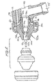
- a conical spray nozzle 90a (Fig. 2)
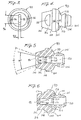
- a fan spray nozzle 90 (Figs. 3-6).
- the nozzle 90a has a circular discharge orifice 92a that is coaxial with the air-fluid mixing chamber and produces a conical spray pattern.
- the size and angle of the conical pattern can be modified by altering the diameter of the discharge orifice.
- the fan nozzle 90 has an elongated or slot-like discharge orifice 92 and produces a fan-shaped spray pattern, i.e., a pattern having generally flat sides and diverging edges as illustrated in Fig. 5.
- the nozzle orifice 92 has a width 94 and height 96. The width 94 is smaller than both the height 96 and the diameter of the mixing chamber, and the height 96 is preferably greater than the mixing chamber diameter.
- the width 94 of the discharge orifice 92 should fall between an upper and a lower limit.
- the lower limit is the average diameter of the particles in the spray materials. If the width 94 is less than the average particle diameter, the particles will tend to occlude the discharge orifice 92 hampering the spray pattern.
- the upper limit is twice the average diameter of the particles in the spray material.
- the width 94 is approximately fifty percent greater than the average particle diameter.
- the spray material can be selected with respect to the width 94.
- the spray material is selected so that the particles in the spray material have an average thickness that is one third smaller than the width 94.
- all of the spray nozzles to be used with the spray gun will have the same external shape and dimensions so as to be readily replaceable, one for the other, thereby facilitating quick and easy changeover when it is desired to vary the spray pattern.
- a description of the features of the fan spray nozzle 90 shown in Figs. 3-6 will serve to describe as well the corresponding features of the conical spray nozzle 90a shown in Fig. 2.
- Corresponding reference numerals are employed to indicate corresponding features, with the corresponding numerals in Fig. 2 being followed by the suffix "a".
- each nozzle comprises a body portion 100 having an outer peripheral surface 102 at its front end that is rearwardly and outwardly tapered and of frustoconical shape.
- An outer peripheral surface 104 at the rear of the nozzle is rearwardly and inwardly tapered and of frustoconical shape for conformable reception in and mating engagement with a complementary frustoconical recess 106 (Fig. 2) formed at the forward end of the gun barrel 12.
- the juncture of the nozzle front and rear surfaces 102 and 104 is defined by a forwardly facing, radially outwardly extending shoulder 108 which is engageable by the cap or bezel 66.
- the cap or bezel is internally threaded and engages complementary external threads on the front end of the gun barrel 12 to sealingly seat the rear surface 104 of the nozzle in the complementary recess 106 in the gun barrel.
- each nozzle can quickly and easily be removed and replaced with another nozzle simply by removal of the cap 66, replacement of the nozzle and reattachment of the cap, as is indicated by the phantom line illustration in Fig. 2.
- each nozzle has a peripheral, circumferentially extending cut 110 therein located for alignment with the gun body air passage 78, thereby to form the annular, circumferential, compressed air gallery or manifold 60.
- a resilient elastomeric O-ring seal 112 (Fig. 2) may be seated in a circumferential groove 114 in the rear surface of the nozzle between the air gallery cut 110 and the rear end of the nozzle.
- the ring 112 thus provides an elastomeric seal at the interface between the nozzle and the gun barrel which supplements the metal to metal seal established by the complementary frustoconical surfaces 104 and 106.
- each fan nozzle 90 is preferably provided on its front peripheral surface 102 with a pair of wrench flats 116 adapted for reception of a wrench for rotating the nozzle without loosening, or with only partial loosening, of the nozzle mounting cap or bezel 66.
- the wrench flats 116 are preferably spaced equal distances outwardly from the length dimension 94 of the fan spray outlet 92 so as to be oriented with the opposite, substantially flat sides of the fan shaped spray, thereby to facilitate orientation of the fan relative to the gun.
- the internal construction of the nozzle is especially critical to attainment of the objects of the invention.
- the nozzle has a stepped axial bore therethrough defining a material entry chamber 120 of a given diameter and an air and fluid mixing chamber 122 of a smaller diameter, with an intervening forwardly tapered shoulder 124 between the chambers.
- a material entry chamber 120 of a given diameter
- an air and fluid mixing chamber 122 of a smaller diameter
- an intervening forwardly tapered shoulder 124 between the chambers.
- Each nozzle is provided with a plurality of circumferentially spaced, forwardly and inwardly inclined air orifices or ports 126 which extend from the air gallery cut 110 into the mixing chamber 122.
- the forward inclination of the ports causes air passing therethrough to impinge in a forward direction and generally tangentially against the fluid material passing through the mixing chamber. Consequently, the air flow complements the fluid flow to mitigate against creation of a back pressure in the mixing chamber that might otherwise tend to drive the fluid material rearwardly into the air orifices or ports 126.
- the angle of air impingement onto the fluid material is preferably in the order of about 30 degrees.
- the air orifices or ports 126 are preferably spaced equal circumferential distances from one another and are preferably six in number to insure thorough and uniform mixing of the air with the fluent material in order to provide a spray pattern of uniform spray density.
- the air ports are spaced circumferentially from the plane of the major axis or dimension 96 of the spray orifice 92 so as not to impinge directly on the fluent material that will form the diverging marginal edges of the fan shaped spray pattern. This assures the integrity and angle of the fan pattern even when air and/or fluid pressures are varied.
- the angle of divergence of the fan shaped spray pattern and thus the height of the pattern are determined by the angle of divergence of the internal surfaces of the nozzle that lead from the peripheral wall of the mixing chamber 122 to the height dimension 96 of the fan orifice 92.
- a divergence angle of 30° is shown in solid lines and a divergence angle of 45° in dotted lines.
- the width 94 of the discharge orifice is a function of the size of the particulate in the fluent material, as previously described, and the height is such as to establish a predetermined relationship between the area of the discharge orifice and the area of the compressed air orifices 126 entering through the peripheral wall of the mixing chamber.
- the area of the nozzle discharge orifice 92 should in particular be greater than the combined areas of the air ports 126 in order to provide for a pressure drop at the discharge orifice to further aid in mitigating development of back pressures in the mixing chamber 122. Also, in order to achieve thorough and proper mixing and atomization, the pressure of the fluent material in the mixing chamber 122 should not exceed the pressure of the air introduced into the chamber. No scientifically precise ratios of area, size and pressure have been determined to be critical to successful operation of the nozzle. It appears to suffice that the mixing chamber 122 be smaller than the entry chamber 120; that the fluid pressure not exceed the air pressure in the mixing chamber; and that the area of the spray orifice be greater than the area of the air ports 126.
- the present invention further provides the significant improvement that the nozzles 90 and 90a are of unitary, one-piece construction in contrast to the conventional three component assembly of the prior art.
- Each nozzle can be manufactured from a single piece of raw material on a single nozzle making machine. Due to their design, the nozzles can be manufactured with quite generous tolerances, thereby minimizing machining time. Consequently, the nozzles are very economical to make, easy to use, readily replaceable one for another, and not prone to loss.
Landscapes
- Nozzles (AREA)
Applications Claiming Priority (2)
| Application Number | Priority Date | Filing Date | Title |
|---|---|---|---|
| US66660896A | 1996-06-18 | 1996-06-18 | |
| US666608 | 1996-06-18 |
Publications (2)
| Publication Number | Publication Date |
|---|---|
| EP0813909A2 true EP0813909A2 (fr) | 1997-12-29 |
| EP0813909A3 EP0813909A3 (fr) | 1999-03-10 |
Family
ID=24674715
Family Applications (1)
| Application Number | Title | Priority Date | Filing Date |
|---|---|---|---|
| EP97420094A Withdrawn EP0813909A3 (fr) | 1996-06-18 | 1997-06-18 | Buse d'atomisation pneumatique de liquide avec mélange interne |
Country Status (2)
| Country | Link |
|---|---|
| EP (1) | EP0813909A3 (fr) |
| JP (1) | JPH1080653A (fr) |
Cited By (4)
| Publication number | Priority date | Publication date | Assignee | Title |
|---|---|---|---|---|
| GB2452580A (en) * | 2007-09-07 | 2009-03-11 | Dave Edward Bickers | Mix and spray nozzle arrangement |
| EP2446792A1 (fr) * | 2010-10-29 | 2012-05-02 | Gruppo Cimbali S.p.A. | Embout remplaçable pour la buse à vapeur d'une machine à café |
| CN116967032A (zh) * | 2023-09-08 | 2023-10-31 | 中山市庆谊金属制品企业有限公司 | 一种能出扇形水花的水枪头及水枪 |
| CN118255458A (zh) * | 2024-04-19 | 2024-06-28 | 南方环境科技(杭州)有限公司 | 一种一体化污水处理方法 |
Family Cites Families (4)
| Publication number | Priority date | Publication date | Assignee | Title |
|---|---|---|---|---|
| FR2231193A5 (en) * | 1973-05-26 | 1974-12-20 | Haute Garonne Ets Auriol Ateli | Spray device for liquid used in machining operations - gas is introduced to atomisation passage through inclined channels |
| GB9220710D0 (en) * | 1992-10-01 | 1992-11-11 | Exploration And Production Nor | Combustion apparatus |
| US5370315A (en) * | 1993-10-15 | 1994-12-06 | Del Gaone; Peter V. | Spray gun for aggregates |
| US5618001A (en) * | 1995-03-20 | 1997-04-08 | Binks Manufacturing Company | Spray gun for aggregates |
-
1997
- 1997-06-18 JP JP16130697A patent/JPH1080653A/ja active Pending
- 1997-06-18 EP EP97420094A patent/EP0813909A3/fr not_active Withdrawn
Cited By (6)
| Publication number | Priority date | Publication date | Assignee | Title |
|---|---|---|---|---|
| GB2452580A (en) * | 2007-09-07 | 2009-03-11 | Dave Edward Bickers | Mix and spray nozzle arrangement |
| GB2452580B (en) * | 2007-09-07 | 2012-04-04 | Dave Edward Bickers | Spraying apparatus |
| EP2446792A1 (fr) * | 2010-10-29 | 2012-05-02 | Gruppo Cimbali S.p.A. | Embout remplaçable pour la buse à vapeur d'une machine à café |
| US8826802B2 (en) | 2010-10-29 | 2014-09-09 | Gruppo Cimbali S.P.A. | Replaceable end-piece for a vapour nozzle of a coffee machine |
| CN116967032A (zh) * | 2023-09-08 | 2023-10-31 | 中山市庆谊金属制品企业有限公司 | 一种能出扇形水花的水枪头及水枪 |
| CN118255458A (zh) * | 2024-04-19 | 2024-06-28 | 南方环境科技(杭州)有限公司 | 一种一体化污水处理方法 |
Also Published As
| Publication number | Publication date |
|---|---|
| JPH1080653A (ja) | 1998-03-31 |
| EP0813909A3 (fr) | 1999-03-10 |
Similar Documents
| Publication | Publication Date | Title |
|---|---|---|
| US5618001A (en) | Spray gun for aggregates | |
| US4927079A (en) | Plural component air spray gun and method | |
| US8640976B2 (en) | Spray gun having mechanism for internally swirling and breaking up a fluid | |
| US4456181A (en) | Gas liquid mixing nozzle | |
| US7762476B2 (en) | Spray gun with improved atomization | |
| US6494387B1 (en) | Low-pressure atomizing spray gun | |
| US5152460A (en) | Spray gun nozzle head | |
| US5102051A (en) | Spray gun | |
| US5553788A (en) | Spray gun assembly and system for fluent materials | |
| JPH09509890A (ja) | 流体噴霧器用重複ノズル | |
| US4123007A (en) | Valve assembly and spraying apparatus therefor | |
| JPS61268369A (ja) | 粉体スプレ−装置及び方法 | |
| JPH07508680A (ja) | 空気噴霧ノズル | |
| US4773597A (en) | Nozzle for spraying liquids | |
| US4073436A (en) | Mixing and/or dispersing and spraying arrangement | |
| US20100308134A1 (en) | Automatic Paint Spray Gun For Two-Component Systems | |
| EP0813909A2 (fr) | Buse d'atomisation pneumatique de liquide avec mélange interne | |
| US4175702A (en) | Air nucleating spary gun | |
| HK1001967A (en) | Internal mix air spray nozzle for spraying fluent materials | |
| US4878621A (en) | Projecting gun and nozzle | |
| US4822644A (en) | Projecting gun and nozzle, and method of use | |
| USRE31163E (en) | Valve assembly and spraying apparatus therefor | |
| JP2000070771A (ja) | スプレーガン及び同装置 | |
| KR19980062641U (ko) | 저비산 페인트 스프레이건 | |
| JPS635141B2 (fr) |
Legal Events
| Date | Code | Title | Description |
|---|---|---|---|
| PUAI | Public reference made under article 153(3) epc to a published international application that has entered the european phase |
Free format text: ORIGINAL CODE: 0009012 |
|
| AK | Designated contracting states |
Kind code of ref document: A2 Designated state(s): AT BE CH DE DK ES FI FR GB GR IE IT LI LU MC NL PT SE |
|
| PUAL | Search report despatched |
Free format text: ORIGINAL CODE: 0009013 |
|
| AK | Designated contracting states |
Kind code of ref document: A3 Designated state(s): AT BE CH DE DK ES FI FR GB GR IE IT LI LU MC NL PT SE |
|
| AKX | Designation fees paid |
Free format text: AT BE CH DE DK ES FI FR GB GR IE IT LI LU MC NL PT SE |
|
| STAA | Information on the status of an ep patent application or granted ep patent |
Free format text: STATUS: THE APPLICATION IS DEEMED TO BE WITHDRAWN |
|
| 18D | Application deemed to be withdrawn |
Effective date: 19990911 |
|
| REG | Reference to a national code |
Ref country code: HK Ref legal event code: WD Ref document number: 1001967 Country of ref document: HK |