EP0814251B1 - Sicherheitssystem für ein Kraftfahrzeug - Google Patents
Sicherheitssystem für ein Kraftfahrzeug Download PDFInfo
- Publication number
- EP0814251B1 EP0814251B1 EP97107653A EP97107653A EP0814251B1 EP 0814251 B1 EP0814251 B1 EP 0814251B1 EP 97107653 A EP97107653 A EP 97107653A EP 97107653 A EP97107653 A EP 97107653A EP 0814251 B1 EP0814251 B1 EP 0814251B1
- Authority
- EP
- European Patent Office
- Prior art keywords
- act
- load
- ref
- internal combustion
- safety system
- Prior art date
- Legal status (The legal status is an assumption and is not a legal conclusion. Google has not performed a legal analysis and makes no representation as to the accuracy of the status listed.)
- Expired - Lifetime
Links
- 238000002485 combustion reaction Methods 0.000 claims description 38
- 239000000446 fuel Substances 0.000 claims description 10
- 238000011156 evaluation Methods 0.000 description 9
- 238000012544 monitoring process Methods 0.000 description 9
- 230000006870 function Effects 0.000 description 8
- 230000008901 benefit Effects 0.000 description 6
- 238000001514 detection method Methods 0.000 description 6
- 230000007257 malfunction Effects 0.000 description 5
- 230000005540 biological transmission Effects 0.000 description 3
- 230000001133 acceleration Effects 0.000 description 2
- 238000010276 construction Methods 0.000 description 2
- 238000012806 monitoring device Methods 0.000 description 2
- 230000001105 regulatory effect Effects 0.000 description 2
- 230000004044 response Effects 0.000 description 2
- 238000012546 transfer Methods 0.000 description 2
- 230000002411 adverse Effects 0.000 description 1
- 238000004378 air conditioning Methods 0.000 description 1
- 230000008859 change Effects 0.000 description 1
- 238000006243 chemical reaction Methods 0.000 description 1
- 230000001276 controlling effect Effects 0.000 description 1
- 238000012937 correction Methods 0.000 description 1
- 230000008878 coupling Effects 0.000 description 1
- 238000010168 coupling process Methods 0.000 description 1
- 238000005859 coupling reaction Methods 0.000 description 1
- 230000000994 depressogenic effect Effects 0.000 description 1
- 238000009795 derivation Methods 0.000 description 1
- 230000000694 effects Effects 0.000 description 1
- 238000005259 measurement Methods 0.000 description 1
- 238000000034 method Methods 0.000 description 1
- 238000012545 processing Methods 0.000 description 1
- 230000009467 reduction Effects 0.000 description 1
Images
Classifications
-
- F—MECHANICAL ENGINEERING; LIGHTING; HEATING; WEAPONS; BLASTING
- F02—COMBUSTION ENGINES; HOT-GAS OR COMBUSTION-PRODUCT ENGINE PLANTS
- F02D—CONTROLLING COMBUSTION ENGINES
- F02D41/00—Electrical control of supply of combustible mixture or its constituents
- F02D41/22—Safety or indicating devices for abnormal conditions
-
- B—PERFORMING OPERATIONS; TRANSPORTING
- B60—VEHICLES IN GENERAL
- B60K—ARRANGEMENT OR MOUNTING OF PROPULSION UNITS OR OF TRANSMISSIONS IN VEHICLES; ARRANGEMENT OR MOUNTING OF PLURAL DIVERSE PRIME-MOVERS IN VEHICLES; AUXILIARY DRIVES FOR VEHICLES; INSTRUMENTATION OR DASHBOARDS FOR VEHICLES; ARRANGEMENTS IN CONNECTION WITH COOLING, AIR INTAKE, GAS EXHAUST OR FUEL SUPPLY OF PROPULSION UNITS IN VEHICLES
- B60K28/00—Safety devices for propulsion-unit control, specially adapted for, or arranged in, vehicles, e.g. preventing fuel supply or ignition in the event of potentially dangerous conditions
- B60K28/10—Safety devices for propulsion-unit control, specially adapted for, or arranged in, vehicles, e.g. preventing fuel supply or ignition in the event of potentially dangerous conditions responsive to conditions relating to the vehicle
-
- B—PERFORMING OPERATIONS; TRANSPORTING
- B60—VEHICLES IN GENERAL
- B60K—ARRANGEMENT OR MOUNTING OF PROPULSION UNITS OR OF TRANSMISSIONS IN VEHICLES; ARRANGEMENT OR MOUNTING OF PLURAL DIVERSE PRIME-MOVERS IN VEHICLES; AUXILIARY DRIVES FOR VEHICLES; INSTRUMENTATION OR DASHBOARDS FOR VEHICLES; ARRANGEMENTS IN CONNECTION WITH COOLING, AIR INTAKE, GAS EXHAUST OR FUEL SUPPLY OF PROPULSION UNITS IN VEHICLES
- B60K28/00—Safety devices for propulsion-unit control, specially adapted for, or arranged in, vehicles, e.g. preventing fuel supply or ignition in the event of potentially dangerous conditions
- B60K28/10—Safety devices for propulsion-unit control, specially adapted for, or arranged in, vehicles, e.g. preventing fuel supply or ignition in the event of potentially dangerous conditions responsive to conditions relating to the vehicle
- B60K28/16—Safety devices for propulsion-unit control, specially adapted for, or arranged in, vehicles, e.g. preventing fuel supply or ignition in the event of potentially dangerous conditions responsive to conditions relating to the vehicle responsive to, or preventing, spinning or skidding of wheels
-
- B—PERFORMING OPERATIONS; TRANSPORTING
- B60—VEHICLES IN GENERAL
- B60W—CONJOINT CONTROL OF VEHICLE SUB-UNITS OF DIFFERENT TYPE OR DIFFERENT FUNCTION; CONTROL SYSTEMS SPECIALLY ADAPTED FOR HYBRID VEHICLES; ROAD VEHICLE DRIVE CONTROL SYSTEMS FOR PURPOSES NOT RELATED TO THE CONTROL OF A PARTICULAR SUB-UNIT
- B60W2710/00—Output or target parameters relating to a particular sub-units
- B60W2710/06—Combustion engines, Gas turbines
- B60W2710/0666—Engine torque
Definitions
- the invention relates to a security system for a motor vehicle with internal combustion engine.
- the security system according to the invention has the advantage that for motor control and for monitoring independent Input variables can be used. If capturing one of the both sizes, so either the motor control or the Monitoring continues to work properly. The engine control falls off, the security system can at least one Emergency operation or decommissioning of the internal combustion engine guarantee.
- the accelerator pedal position corresponds in principle the driver's desire to have the vehicle in one to move the given state.
- the engine management system based on the Accelerator pedal position
- Setpoints for the operating parameters of the internal combustion engine predefined and set accordingly.
- a setpoint for the safety system for the expected response of the vehicle based on the accelerator pedal position determined and with the actual response compared.
- the reaction of the vehicle can be detected on the basis of at least one wheel speed.
- the wheel speed n wheel does not have to be recorded separately here, but can be transferred from the traction control system to the safety system. This means that no additional construction work is required for the security system.
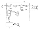
- the load is detected indirectly by measuring the current air mass flow m ⁇ ist in the intake line 2 of the internal combustion engine, not shown.
- the current air mass flow m ⁇ is set , for example, using a throttle valve 5 and can be determined using a hot wire air mass meter 6.
- the evaluation device 4 is referred to below as an engine control unit.
- the engine control unit 4 is now in block 7 from the accelerator pedal position FP a vehicle propulsion request - for example, a driver's desired torque M soll-FP - and from this then in block 8, a desired value for the operating state of the internal combustion engine characterizing operating parameters - for example, a load setpoint load should - determined.
- a desired value for the operating state of the internal combustion engine characterizing operating parameters - for example, a load setpoint load should - determined.
- a target throttle value ⁇ is to be determined and should ⁇ the throttle valve 5 by means of a throttle valve adjustment, not shown, to this desired value set.
- the engine control unit is given 4 further operating parameters, such as engine speed or engine temperature Provided.
- the engine control unit 4 in addition to the throttle valve position also other operating parameters, For example, ignition timing (block 15) or amount of fuel (Block 16).
- ignition timing block 15
- amount of fuel Block 16
- a sensor for detecting a wheel speed n wheel is provided on at least one vehicle wheel 3 for this purpose.
- This wheel speed n wheel is transferred to the engine control unit 4 via a data line.
- the actual value of the vehicle propulsion in the form of the output torque M ist is determined in block 12 from the speed signal n wheel by time derivation and subsequent multiplication by the vehicle mass.
- the two input variables M soll-FP , M ist apart from minor fluctuations, should essentially match. Deviations can only occur when a malfunction occurs in signal acquisition, transmission or processing.
- the difference value ⁇ M is therefore continuously compared in block 14 with a predetermined threshold value M threshold . If it is determined here that the difference value ⁇ M exceeds the threshold value M threshold over a predetermined period of time, an error is recognized.
- an error signal is generated and displayed to the driver and / or stored in a memory for later evaluation.
- the operational safety of the internal combustion engine cannot be guaranteed solely on the basis of this measure. It may also be necessary to intervene in the engine control.
- One possibility is to determine a corrected, higher-priority target torque M corr in block 14 on the basis of the difference value ⁇ M and to transfer it to block 7.
- a further possibility of reacting to the detection of an error state is to reduce the output torque M by an ignition intervention, for example a temporary early or late adjustment of the ignition point.
- a corresponding error signal is again generated in block 14 and fuel metering (block 16) is transferred
- Block 14 thus represents the actual module for monitoring the internal combustion engine.
- the input variables of the driver's desired torque M soll-FP and output torque M is compared and generates a deviation corresponding signals by reducing the load setting (block 8), an ignition intervention (block 15) and / or a fuel cut-off (16) an excessive output torque M is to be prevented.
- the exchange of data or measurement signals between the individual sensors and evaluation devices can be used via any Data connections can be realized. In the simplest case all devices connected with simple electrical cables.
- the throttle valve adjustment knows generally a mechanical device, for example in the form of a spring, on which the throttle valve 5 in Closed position transferred so that the internal combustion engine in Is operated idle. Of course, in this case however, it should also be provided that the internal combustion engine by a shutdown of the fuel supply is stopped.
- the safety system described has the advantage that independent variables are used to control or monitor the internal combustion engine. Any operating variable characterizing the engine load load is recorded for control purposes. In addition to or instead of the instantaneous air mass flow m ⁇ , the intake manifold pressure and / or the throttle valve position can also be used here. The output torque M ist of the vehicle is also determined for monitoring on the basis of a wheel speed n wheel . If the detection of the air mass flow m ⁇ ist fails, the engine control will work incorrectly. However, the safety system works independently of this input variable and can, as already described above, switch the internal combustion engine into an emergency mode or shut it down.
- the safety system described can also be used in vehicles with a so-called dynamic torque setting. Since such a motor control is no direct coupling is ⁇ between the throttle valve position, particularly in dynamic operating conditions and engine load load is more, it is no longer possible, the monitoring is ⁇ on the basis of the throttle angle execute. If the engine control system also has a torque interface, via which additional control components are to act on the target engine torque M , the function of this additional system can also be at least partially monitored with the safety system. The engagement of such an auxiliary system leads to a reduction of the setpoint torque M soll, so this is irrelevant for the operational safety. An inadmissible increase in the target torque M should be recognized by such an additional system, however, by the security system.
- the driver's desired torque M target is determined on the basis of the accelerator pedal position FP.
- suitable input variables for example the output signal of an automatic speed control.
- the wheel speed n wheel there are also further possibilities for the detection of the wheel speed n wheel .
- the speeds of several or all wheels 7 can be measured and an effective wheel speed n wheel can be determined therefrom in any manner.
- the output torque M ist can be determined at any point on the drive train. Only the definition of the torque interface has to be adapted to the selected position in the drive train.
- a traction control system is additionally provided in the vehicle.
- This can be a simple system, for example in the form of an anti-lock braking system, or a more complex system, such as anti-slip or driving dynamics control.
- the speeds of individual or all wheels 7 are recorded and evaluated. It is therefore possible to transfer the wheel speed n wheel determined by the traction control system 13 to the evaluation device 4. No additional construction work is therefore necessary for the safety system, since all sensors and evaluation devices are already required for other tasks.
- the engine control and the safety system are combined in a common evaluation device 4. However, it is also possible to provide separate devices for this. On the other hand, it is also possible to integrate further functions, such as the traction control system, into the single evaluation device 4.
- the security system described with reference to the drawing represents only one possible exemplary embodiment. Therefore, the scope of protection should not be limited to the example shown. Rather, the idea according to the invention can be applied to almost all motor controls.
- As the characteristic variable for the operating state of the internal combustion engine it is not only the engine load that is considered. Rather, the operating state can also be characterized by the efficiency - for example as a function of ignition timing, lambda or fuel cut-off -, the number of consumers - for example air conditioning or alternator - or the state parameters for the functions of cylinder cut-off, sequential fuel cut-off, gear, gear change or power transmission , Of course, a combination of several of these or other sizes can also be used.
- all variables that influence the condition of the internal combustion engine and thus directly or indirectly the propulsion of the vehicle can be considered as input variables.
- the vehicle jacking request comes also target acceleration or target speed, each measured at the motor shaft, gear shaft or directly on the vehicle wheel, in Question.
- target acceleration or target speed each measured at the motor shaft, gear shaft or directly on the vehicle wheel
- the fuel quantity specification, the Throttle valve angle requirement or setpoints for the air mass flow or the load can be used.
- vehicle propulsion can also determine the speed, the acceleration or the moment anywhere in the Powertrain can be detected.
- Vehicle yaw, pitch or roll angle in question are also be used.
- the only decisive factor is the principle, based on the Driver's request to determine two setpoints, one setpoint corresponds to the desired vehicle jacking and the other Setpoint is a control or regulating variable of the internal combustion engine Setting of the desired vehicle propulsion concerns. Moreover two independent measured values are recorded, of which one each the actual value assigned to the corresponding setpoint is determined. Finally, two independent functions are provided, whereby one for controlling or regulating the internal combustion engine, as well as to determine the target and actual value for vehicle jacking serves, and the second the operation of the internal combustion engine based on those provided by the first control unit Setpoints and actual values for vehicle jacking are monitored and if necessary, control commands to the first function for correction a malfunction or to shut down the internal combustion engine sends. These two functions can be used together in the Engine control unit 4 can be integrated, but two can also separate devices are provided. For example the monitoring function also in the traction control system 13 to get integrated.
Landscapes
- Engineering & Computer Science (AREA)
- Chemical & Material Sciences (AREA)
- Combustion & Propulsion (AREA)
- Mechanical Engineering (AREA)
- General Engineering & Computer Science (AREA)
- Transportation (AREA)
- Control Of Vehicle Engines Or Engines For Specific Uses (AREA)
- Combined Controls Of Internal Combustion Engines (AREA)
- Electrical Control Of Air Or Fuel Supplied To Internal-Combustion Engine (AREA)
- Hybrid Electric Vehicles (AREA)
- Electric Propulsion And Braking For Vehicles (AREA)
Description
Claims (8)
- Sicherheitssystem für ein Kraftfahrzeug mit Brennkraftmaschine mit Vorrichtungen zur Ermittlungund mit Vorrichtungender Fahrpedalstellung (FP),zumindest eines den Betriebszustand der Brennkraftmaschine charakterisierenden Betriebsparameters (Lastist),zumindest eines den Fahrzeugvortrieb charakterisierenden Größe (nist),einer Fahrzeugvortriebs-Anforderung (Msoll-FP) und eines Sollwertes für den den Betriebszustand der Brennkraftmaschine charakterisierenden Betriebsparameter (Lastsoll) auf der Basis der Fahrpedalstellung (FP),zur Einstellung des den Betriebszustand der Brennkraftmaschine charakterisierenden Betriebsparameter (Lastist) auf den ermittelten Sollwert (Lastsoll), undzum laufenden Vergleich der Fahrzeugvortriebswerte (Mist, Msoll-FP), wobei bei einer Abweichung des Istwertes (Mist) vom Sollwert (Msoll-FP) ein Fehler erkannt wird.
- Sicherheitssystem nach Anspruch 1,
dadurch gekennzeichnet, daß eine Abweichung dann erkannt wird, wenn die Differenz ΔM = Mist - Msoll-FP) zwischen den Fahrzeugvortriebswerten (Mist, Msoll-FP) über einen vorgegebenen Zeitraum einen vorgegebenen Schwellwert (Mschwell) übersteigt. - Sicherheitssystem nach Anspruch 1,
dadurch gekennzeichnet, daß dann, wenn ein Fehler erkannt wird, die Einstellung des den Betriebszustand der Brennkraftmaschine charakterisierenden Betriebsparameteres (Lastist) auf der Basis des Differenzwertes (ΔM) erfolgt. - Sicherheitssystem nach Anspruch 1,
dadurch gekennzeichnet, daß dann, wenn ein Fehler erkannt wird, ein Signal zur Reduzierung des Fahrzeugvortriebs-Istwertes (Mist) an die Zündverstellung (15) übergeben wird. - Sicherheitssystem nach Anspruch 4,
dadurch gekennzeichnet, daß dann, wenn trotz Zündungseingriff der Fahrzeugvortriebs-Istwert (Mist) die Fahrzeugvortriebs-Anforderung (Msoil-FP) übersteigt, ein Signal zur Kraftstoffabschaltung an die Kraftstoffdosierung (16) übergeben wird. - Sicherheitssystem nach Anspruch 1,
dadurch gekennzeichnet, daß dann, wenn ein Fehler erkannt wird, ein Fehlersignal erzeugt und dem Fahrer angezeigt und/oder in einem Speicher abgelegt wird. - Sicherheitssystem nach Anspruch 1,
dadurch gekennzeichnet,daß neben der Fahrpedalstellung (FP) die Motorlast (Lastist) und die Drehzahl (nRad) an zumindest einem Fahrzeugrad (3) erfaßt wird,daß ein Last-Sollwert (Lastsoll) und ein Fahrerwunschmoment (Msoll-FP) auf der Basis der Fahrpedalstellung (FP), und ein Ausgangsmoment (Mist) auf der Basis der zumindest einen Raddrehzahl (nRad) ermittelt wird und der Last-Istwert (Lastist) durch Beeinflussung eines die Motorlast (Lastist) beeinflussenden Betriebsparameters (αist) auf den Last-Sollwert (Lastsoll) eingestellt wird, unddaß laufend die Ausgangsmomente (Mist, Msoll-FP) verglichen und bei einer Abweichung des Istmomentes (Mist) vom Fahrerwunschmoment (Msoll-FP) ein Fehler erkannt wird. - Sicherheitssystem nach Anspruch 7,
dadurch gekennzeichnet, daß zusätzlich ein Traktionskontrollsystem vorgesehen ist und daß die Raddrehzahl (nRad) vom Traktionskontrollsystem (13) erfaßt und an die Auswertevorrichtung (4) übergeben wird.
Applications Claiming Priority (2)
| Application Number | Priority Date | Filing Date | Title |
|---|---|---|---|
| DE19624822 | 1996-06-21 | ||
| DE19624822A DE19624822C1 (de) | 1996-06-21 | 1996-06-21 | Sicherheitssystem für ein Kraftfahrzeug |
Publications (3)
| Publication Number | Publication Date |
|---|---|
| EP0814251A2 EP0814251A2 (de) | 1997-12-29 |
| EP0814251A3 EP0814251A3 (de) | 1999-08-18 |
| EP0814251B1 true EP0814251B1 (de) | 2002-09-25 |
Family
ID=7797602
Family Applications (1)
| Application Number | Title | Priority Date | Filing Date |
|---|---|---|---|
| EP97107653A Expired - Lifetime EP0814251B1 (de) | 1996-06-21 | 1997-05-09 | Sicherheitssystem für ein Kraftfahrzeug |
Country Status (4)
| Country | Link |
|---|---|
| US (1) | US5987372A (de) |
| EP (1) | EP0814251B1 (de) |
| DE (1) | DE19624822C1 (de) |
| ES (1) | ES2183043T3 (de) |
Families Citing this family (10)
| Publication number | Priority date | Publication date | Assignee | Title |
|---|---|---|---|---|
| US20030193413A1 (en) * | 1993-05-18 | 2003-10-16 | Jones M. Kelly | Business methods for notification systems |
| US5949143A (en) * | 1998-01-22 | 1999-09-07 | Advanced Micro Devices, Inc. | Semiconductor interconnect structure with air gap for reducing intralayer capacitance in metal layers in damascene metalization process |
| DE59913007D1 (de) * | 1998-07-29 | 2006-03-30 | Daimler Chrysler Ag | Verfahren zur Drehmomenteinstellung |
| DE19916725C2 (de) * | 1999-04-13 | 2001-11-08 | Daimler Chrysler Ag | Verfahren zur Drehmomentüberwachung bei Otto-Motoren in Kraftfahrzeugen |
| DE19954535C2 (de) * | 1999-11-12 | 2001-10-25 | Bosch Gmbh Robert | Verfahren zur Plausibilitätsprüfung der gemessenen Last bei einer Brennkraftmaschine mit variabler Ventilhubsteuerung |
| DE10032110C2 (de) | 2000-07-01 | 2002-10-31 | Mtu Friedrichshafen Gmbh | Diagnosesystem für eine Brennkraftmaschine |
| DE102005040780B4 (de) | 2005-08-29 | 2018-11-22 | Robert Bosch Gmbh | Verfahren und Motorsteuerungsgerät zur Verfügbarkeitserhöhung von Kraftfahrzeugmotoren |
| DE102008063069A1 (de) * | 2008-12-23 | 2010-07-01 | Bombardier Transportation Gmbh | Erkennung der Unterbrechung des Antriebsleistungsflusses eines Fahrzeugs |
| JP5730636B2 (ja) * | 2011-03-25 | 2015-06-10 | 本田技研工業株式会社 | トラクション制御装置 |
| DE102011075609A1 (de) | 2011-05-10 | 2012-11-15 | Bayerische Motoren Werke Aktiengesellschaft | Beschleunigungsbasierte Sicherheitsüberwachung eines Antriebs eines Kraftfahrzeugs |
Family Cites Families (13)
| Publication number | Priority date | Publication date | Assignee | Title |
|---|---|---|---|---|
| JPH01162055U (de) * | 1988-04-30 | 1989-11-10 | ||
| JPH01162084U (de) * | 1988-04-30 | 1989-11-10 | ||
| US4985837A (en) * | 1988-07-27 | 1991-01-15 | Mitsubishi Jidosha Kogyo Kabushiki Kaisha | Traction control apparatus |
| JPH02267342A (ja) * | 1989-04-07 | 1990-11-01 | Mitsubishi Motors Corp | エンジン吸気系における故障診断装置 |
| US5638677A (en) * | 1991-03-29 | 1997-06-17 | Hitachi Construction Machinery Co., Ltd. | Control device for hydraulically propelled work vehicle |
| US5373219A (en) * | 1992-03-31 | 1994-12-13 | General Electric Company | Control system for an electrically propelled traction vehicle |
| US5432413A (en) * | 1992-03-31 | 1995-07-11 | General Electric Company | Control system for an electrically propelled traction vehicle |
| US5280223A (en) * | 1992-03-31 | 1994-01-18 | General Electric Company | Control system for an electrically propelled traction vehicle |
| DE4229774C2 (de) * | 1992-09-05 | 2002-06-20 | Bosch Gmbh Robert | Vorrichtung zur Steuerung einer Brennkraftmaschine |
| US5679985A (en) * | 1992-09-23 | 1997-10-21 | International Business Machines Corporation | Power supply with automatic recovery system |
| DE4315885C1 (de) * | 1993-05-12 | 1994-11-03 | Daimler Benz Ag | Verfahren zur Drehmomenteinstellung |
| JP3024460B2 (ja) * | 1993-10-22 | 2000-03-21 | 日産自動車株式会社 | エンジンのスロットル制御装置 |
| DE4407475C2 (de) * | 1994-03-07 | 2002-11-14 | Bosch Gmbh Robert | Verfahren und Vorrichtung zur Steuerung eines Fahrzeugs |
-
1996
- 1996-06-21 DE DE19624822A patent/DE19624822C1/de not_active Expired - Lifetime
-
1997
- 1997-05-09 ES ES97107653T patent/ES2183043T3/es not_active Expired - Lifetime
- 1997-05-09 EP EP97107653A patent/EP0814251B1/de not_active Expired - Lifetime
- 1997-06-19 US US08/879,037 patent/US5987372A/en not_active Expired - Lifetime
Also Published As
| Publication number | Publication date |
|---|---|
| US5987372A (en) | 1999-11-16 |
| ES2183043T3 (es) | 2003-03-16 |
| EP0814251A2 (de) | 1997-12-29 |
| EP0814251A3 (de) | 1999-08-18 |
| DE19624822C1 (de) | 1997-08-14 |
Similar Documents
| Publication | Publication Date | Title |
|---|---|---|
| DE19536038B4 (de) | Verfahren und Vorrichtung zur Steuerung der Antriebseinheit eines Kraftfahrzeugs | |
| EP0536557B1 (de) | Vorrichtung zur Steuerung der Antriebsleistung eines Fahrzeugs | |
| DE10237167B4 (de) | Verfahren zur Steuerung eines automatisierten Schaltgetriebes | |
| DE102005016965B4 (de) | Elektronische Drosselsteuervorrichtung | |
| DE4118736C2 (de) | Steuervorrichtung | |
| EP0950148B1 (de) | Verfahren und vorrichtung zur steuerung der antriebseinheit eines fahrzeugs | |
| DE10150631B4 (de) | Flurförderzeug mit Schnittstelle für Diagnosedaten | |
| DE19922740A1 (de) | System zum Steuern des Motorbremsmoments im Schubbetrieb | |
| DE10226579A1 (de) | Motorsteuersystem | |
| DE10234434B4 (de) | Verfahren zum Steuern einer Drosselklappe eines Motors eines Kraftfahrzeugs | |
| DE69608255T2 (de) | Kupplungssteuerung mit integriertem sicherheitssystem, elektischer notsteuereinrichtung und verfahren zur steuerung | |
| DE19624822C1 (de) | Sicherheitssystem für ein Kraftfahrzeug | |
| EP0814252B1 (de) | Sicherheitssystem für ein Kraftfahrzeug | |
| DE102012201653B4 (de) | Schaltungsanordnung in einem elektronischen Steuergerät eines Kraftfahrzeuges zur Erkennung von Fehlern | |
| DE4314118B4 (de) | Verfahren und Vorrichtung zur Steuerung der Antriebsleistung eines Fahrzeugs | |
| EP0814250B1 (de) | Sicherheitssystem für ein Kraftfahrzeug | |
| DE19750026A1 (de) | Verfahren und Vorrichtung zum Betreiben von Steuereinrichtungen für ein Fahrzeug | |
| WO1991002147A1 (de) | Verfahren und vorrichtung zur steuerung und/oder regelung der motorleistung einer brennkraftmaschine eines kraftfahrzeugs | |
| DE19719518B4 (de) | Verfahren und Vorrichtung zur Steuerung einer Antriebseinheit eines Kraftfahrzeugs | |
| DE102005040780B4 (de) | Verfahren und Motorsteuerungsgerät zur Verfügbarkeitserhöhung von Kraftfahrzeugmotoren | |
| EP1310415B1 (de) | Verfahren zur Fahrzeugsteuerung | |
| DE4223253A1 (de) | Steuereinrichtung für ein Fahrzeug | |
| DE4411531B4 (de) | Verfahren und Vorrichtung zur Steuerung eines Stellelements einer Antriebseinheit in einem Fahrzeug | |
| DE19939412B4 (de) | Verfahren und Vorrichtung zur Steuerung der Fahrzeugantriebsleistung | |
| DE19926324A1 (de) | Vorrichtung und Verfahren zum Betätigen einer Kupplung sowie Kupplungseinrichtung |
Legal Events
| Date | Code | Title | Description |
|---|---|---|---|
| PUAI | Public reference made under article 153(3) epc to a published international application that has entered the european phase |
Free format text: ORIGINAL CODE: 0009012 |
|
| AK | Designated contracting states |
Kind code of ref document: A2 Designated state(s): DE ES FR GB IT Kind code of ref document: A2 Designated state(s): ES FR GB IT |
|
| RAP1 | Party data changed (applicant data changed or rights of an application transferred) |
Owner name: DAIMLERCHRYSLER AG |
|
| PUAL | Search report despatched |
Free format text: ORIGINAL CODE: 0009013 |
|
| AK | Designated contracting states |
Kind code of ref document: A3 Designated state(s): DE ES FR GB IT |
|
| 17P | Request for examination filed |
Effective date: 19990715 |
|
| GRAG | Despatch of communication of intention to grant |
Free format text: ORIGINAL CODE: EPIDOS AGRA |
|
| GRAG | Despatch of communication of intention to grant |
Free format text: ORIGINAL CODE: EPIDOS AGRA |
|
| GRAH | Despatch of communication of intention to grant a patent |
Free format text: ORIGINAL CODE: EPIDOS IGRA |
|
| 17Q | First examination report despatched |
Effective date: 20020327 |
|
| GRAH | Despatch of communication of intention to grant a patent |
Free format text: ORIGINAL CODE: EPIDOS IGRA |
|
| RBV | Designated contracting states (corrected) |
Designated state(s): ES FR GB IT |
|
| GRAA | (expected) grant |
Free format text: ORIGINAL CODE: 0009210 |
|
| REG | Reference to a national code |
Ref country code: DE Ref legal event code: 8566 |
|
| AK | Designated contracting states |
Kind code of ref document: B1 Designated state(s): ES FR GB IT |
|
| REG | Reference to a national code |
Ref country code: GB Ref legal event code: FG4D Free format text: NOT ENGLISH |
|
| GBT | Gb: translation of ep patent filed (gb section 77(6)(a)/1977) |
Effective date: 20021128 |
|
| REG | Reference to a national code |
Ref country code: ES Ref legal event code: FG2A Ref document number: 2183043 Country of ref document: ES Kind code of ref document: T3 |
|
| ET | Fr: translation filed | ||
| PLBE | No opposition filed within time limit |
Free format text: ORIGINAL CODE: 0009261 |
|
| STAA | Information on the status of an ep patent application or granted ep patent |
Free format text: STATUS: NO OPPOSITION FILED WITHIN TIME LIMIT |
|
| 26N | No opposition filed |
Effective date: 20030626 |
|
| PGFP | Annual fee paid to national office [announced via postgrant information from national office to epo] |
Ref country code: GB Payment date: 20050503 Year of fee payment: 9 |
|
| PGFP | Annual fee paid to national office [announced via postgrant information from national office to epo] |
Ref country code: FR Payment date: 20050512 Year of fee payment: 9 |
|
| PGFP | Annual fee paid to national office [announced via postgrant information from national office to epo] |
Ref country code: ES Payment date: 20050513 Year of fee payment: 9 |
|
| PG25 | Lapsed in a contracting state [announced via postgrant information from national office to epo] |
Ref country code: GB Free format text: LAPSE BECAUSE OF NON-PAYMENT OF DUE FEES Effective date: 20060509 |
|
| PG25 | Lapsed in a contracting state [announced via postgrant information from national office to epo] |
Ref country code: ES Free format text: LAPSE BECAUSE OF NON-PAYMENT OF DUE FEES Effective date: 20060510 |
|
| PGFP | Annual fee paid to national office [announced via postgrant information from national office to epo] |
Ref country code: IT Payment date: 20060531 Year of fee payment: 10 |
|
| GBPC | Gb: european patent ceased through non-payment of renewal fee |
Effective date: 20060509 |
|
| REG | Reference to a national code |
Ref country code: FR Ref legal event code: ST Effective date: 20070131 |
|
| REG | Reference to a national code |
Ref country code: ES Ref legal event code: FD2A Effective date: 20060510 |
|
| PG25 | Lapsed in a contracting state [announced via postgrant information from national office to epo] |
Ref country code: FR Free format text: LAPSE BECAUSE OF NON-PAYMENT OF DUE FEES Effective date: 20060531 |
|
| PG25 | Lapsed in a contracting state [announced via postgrant information from national office to epo] |
Ref country code: IT Free format text: LAPSE BECAUSE OF NON-PAYMENT OF DUE FEES Effective date: 20070509 |