EP0814285B1 - Transmission automatique à plusiers vitesses et convertisseur de couple pontable - Google Patents
Transmission automatique à plusiers vitesses et convertisseur de couple pontable Download PDFInfo
- Publication number
- EP0814285B1 EP0814285B1 EP97303939A EP97303939A EP0814285B1 EP 0814285 B1 EP0814285 B1 EP 0814285B1 EP 97303939 A EP97303939 A EP 97303939A EP 97303939 A EP97303939 A EP 97303939A EP 0814285 B1 EP0814285 B1 EP 0814285B1
- Authority
- EP
- European Patent Office
- Prior art keywords
- converter
- pressure
- clutch
- torque
- valve
- Prior art date
- Legal status (The legal status is an assumption and is not a legal conclusion. Google has not performed a legal analysis and makes no representation as to the accuracy of the status listed.)
- Expired - Lifetime
Links
Images




Classifications
-
- F—MECHANICAL ENGINEERING; LIGHTING; HEATING; WEAPONS; BLASTING
- F16—ENGINEERING ELEMENTS AND UNITS; GENERAL MEASURES FOR PRODUCING AND MAINTAINING EFFECTIVE FUNCTIONING OF MACHINES OR INSTALLATIONS; THERMAL INSULATION IN GENERAL
- F16H—GEARING
- F16H61/00—Control functions within control units of change-speed- or reversing-gearings for conveying rotary motion ; Control of exclusively fluid gearing, friction gearing, gearings with endless flexible members or other particular types of gearing
- F16H61/02—Control functions within control units of change-speed- or reversing-gearings for conveying rotary motion ; Control of exclusively fluid gearing, friction gearing, gearings with endless flexible members or other particular types of gearing characterised by the signals used
- F16H61/0202—Control functions within control units of change-speed- or reversing-gearings for conveying rotary motion ; Control of exclusively fluid gearing, friction gearing, gearings with endless flexible members or other particular types of gearing characterised by the signals used the signals being electric
- F16H61/0204—Control functions within control units of change-speed- or reversing-gearings for conveying rotary motion ; Control of exclusively fluid gearing, friction gearing, gearings with endless flexible members or other particular types of gearing characterised by the signals used the signals being electric for gearshift control, e.g. control functions for performing shifting or generation of shift signal
- F16H61/0206—Layout of electro-hydraulic control circuits, e.g. arrangement of valves
-
- F—MECHANICAL ENGINEERING; LIGHTING; HEATING; WEAPONS; BLASTING
- F16—ENGINEERING ELEMENTS AND UNITS; GENERAL MEASURES FOR PRODUCING AND MAINTAINING EFFECTIVE FUNCTIONING OF MACHINES OR INSTALLATIONS; THERMAL INSULATION IN GENERAL
- F16H—GEARING
- F16H61/00—Control functions within control units of change-speed- or reversing-gearings for conveying rotary motion ; Control of exclusively fluid gearing, friction gearing, gearings with endless flexible members or other particular types of gearing
- F16H61/14—Control of torque converter lock-up clutches
- F16H61/143—Control of torque converter lock-up clutches using electric control means
-
- F—MECHANICAL ENGINEERING; LIGHTING; HEATING; WEAPONS; BLASTING
- F16—ENGINEERING ELEMENTS AND UNITS; GENERAL MEASURES FOR PRODUCING AND MAINTAINING EFFECTIVE FUNCTIONING OF MACHINES OR INSTALLATIONS; THERMAL INSULATION IN GENERAL
- F16H—GEARING
- F16H59/00—Control inputs to control units of change-speed- or reversing-gearings for conveying rotary motion
- F16H59/36—Inputs being a function of speed
- F16H59/38—Inputs being a function of speed of gearing elements
- F16H2059/385—Turbine speed
-
- F—MECHANICAL ENGINEERING; LIGHTING; HEATING; WEAPONS; BLASTING
- F16—ENGINEERING ELEMENTS AND UNITS; GENERAL MEASURES FOR PRODUCING AND MAINTAINING EFFECTIVE FUNCTIONING OF MACHINES OR INSTALLATIONS; THERMAL INSULATION IN GENERAL
- F16H—GEARING
- F16H59/00—Control inputs to control units of change-speed- or reversing-gearings for conveying rotary motion
- F16H59/36—Inputs being a function of speed
- F16H59/46—Inputs being a function of speed dependent on a comparison between speeds
- F16H2059/465—Detecting slip, e.g. clutch slip ratio
- F16H2059/467—Detecting slip, e.g. clutch slip ratio of torque converter
-
- F—MECHANICAL ENGINEERING; LIGHTING; HEATING; WEAPONS; BLASTING
- F16—ENGINEERING ELEMENTS AND UNITS; GENERAL MEASURES FOR PRODUCING AND MAINTAINING EFFECTIVE FUNCTIONING OF MACHINES OR INSTALLATIONS; THERMAL INSULATION IN GENERAL
- F16H—GEARING
- F16H61/00—Control functions within control units of change-speed- or reversing-gearings for conveying rotary motion ; Control of exclusively fluid gearing, friction gearing, gearings with endless flexible members or other particular types of gearing
- F16H61/0021—Generation or control of line pressure
- F16H2061/0037—Generation or control of line pressure characterised by controlled fluid supply to lubrication circuits of the gearing
-
- F—MECHANICAL ENGINEERING; LIGHTING; HEATING; WEAPONS; BLASTING
- F16—ENGINEERING ELEMENTS AND UNITS; GENERAL MEASURES FOR PRODUCING AND MAINTAINING EFFECTIVE FUNCTIONING OF MACHINES OR INSTALLATIONS; THERMAL INSULATION IN GENERAL
- F16H—GEARING
- F16H61/00—Control functions within control units of change-speed- or reversing-gearings for conveying rotary motion ; Control of exclusively fluid gearing, friction gearing, gearings with endless flexible members or other particular types of gearing
- F16H61/14—Control of torque converter lock-up clutches
- F16H61/143—Control of torque converter lock-up clutches using electric control means
- F16H2061/145—Control of torque converter lock-up clutches using electric control means for controlling slip, e.g. approaching target slip value
-
- F—MECHANICAL ENGINEERING; LIGHTING; HEATING; WEAPONS; BLASTING
- F16—ENGINEERING ELEMENTS AND UNITS; GENERAL MEASURES FOR PRODUCING AND MAINTAINING EFFECTIVE FUNCTIONING OF MACHINES OR INSTALLATIONS; THERMAL INSULATION IN GENERAL
- F16H—GEARING
- F16H61/00—Control functions within control units of change-speed- or reversing-gearings for conveying rotary motion ; Control of exclusively fluid gearing, friction gearing, gearings with endless flexible members or other particular types of gearing
- F16H61/14—Control of torque converter lock-up clutches
- F16H61/143—Control of torque converter lock-up clutches using electric control means
- F16H2061/146—Control of torque converter lock-up clutches using electric control means for smoothing gear shift shock
-
- F—MECHANICAL ENGINEERING; LIGHTING; HEATING; WEAPONS; BLASTING
- F16—ENGINEERING ELEMENTS AND UNITS; GENERAL MEASURES FOR PRODUCING AND MAINTAINING EFFECTIVE FUNCTIONING OF MACHINES OR INSTALLATIONS; THERMAL INSULATION IN GENERAL
- F16H—GEARING
- F16H2312/00—Driving activities
- F16H2312/02—Driving off
-
- F—MECHANICAL ENGINEERING; LIGHTING; HEATING; WEAPONS; BLASTING
- F16—ENGINEERING ELEMENTS AND UNITS; GENERAL MEASURES FOR PRODUCING AND MAINTAINING EFFECTIVE FUNCTIONING OF MACHINES OR INSTALLATIONS; THERMAL INSULATION IN GENERAL
- F16H—GEARING
- F16H59/00—Control inputs to control units of change-speed- or reversing-gearings for conveying rotary motion
- F16H59/36—Inputs being a function of speed
-
- F—MECHANICAL ENGINEERING; LIGHTING; HEATING; WEAPONS; BLASTING
- F16—ENGINEERING ELEMENTS AND UNITS; GENERAL MEASURES FOR PRODUCING AND MAINTAINING EFFECTIVE FUNCTIONING OF MACHINES OR INSTALLATIONS; THERMAL INSULATION IN GENERAL
- F16H—GEARING
- F16H59/00—Control inputs to control units of change-speed- or reversing-gearings for conveying rotary motion
- F16H59/36—Inputs being a function of speed
- F16H59/44—Inputs being a function of speed dependent on machine speed, e.g. the vehicle speed
-
- F—MECHANICAL ENGINEERING; LIGHTING; HEATING; WEAPONS; BLASTING
- F16—ENGINEERING ELEMENTS AND UNITS; GENERAL MEASURES FOR PRODUCING AND MAINTAINING EFFECTIVE FUNCTIONING OF MACHINES OR INSTALLATIONS; THERMAL INSULATION IN GENERAL
- F16H—GEARING
- F16H59/00—Control inputs to control units of change-speed- or reversing-gearings for conveying rotary motion
- F16H59/68—Inputs being a function of gearing status
- F16H59/72—Inputs being a function of gearing status dependent on oil characteristics, e.g. temperature, viscosity
-
- F—MECHANICAL ENGINEERING; LIGHTING; HEATING; WEAPONS; BLASTING
- F16—ENGINEERING ELEMENTS AND UNITS; GENERAL MEASURES FOR PRODUCING AND MAINTAINING EFFECTIVE FUNCTIONING OF MACHINES OR INSTALLATIONS; THERMAL INSULATION IN GENERAL
- F16H—GEARING
- F16H61/00—Control functions within control units of change-speed- or reversing-gearings for conveying rotary motion ; Control of exclusively fluid gearing, friction gearing, gearings with endless flexible members or other particular types of gearing
- F16H61/0021—Generation or control of line pressure
Definitions
- the invention relates to multiple ratio torque converter transmissions for automotive vehicles and to electronic-hydraulic controls for effecting engagement and release of a converter clutch.
- Multiple ratio planetary transmissions situated in an automotive vehicle driveline typically include a hydrokinetic torque converter situated between torque input planetary gearing of the transmission and a throttle-controlled internal combustion engine.
- the gearing comprises two simple planetary gear units arranged in a manner similar to the gearing arrangement of the well known Simpson gear set.
- Located between the turbine of the torque converter and the input elements of the Simpson gearing is a third simple planetary gear unit with a friction clutch adapted to connect two elements of the third gear unit together for rotation in unison.
- a friction brake also is used for anchoring a reaction element of the planetary gear unit.
- An overrunning coupling establishes one-way torque flow between two elements of the gearing.
- the brake is arranged in series relationship with respect to the clutch.
- a second overrunning coupling in a gear unit of the Simpson gearing is used for the purpose of establishing a non-synchronous ratio shift.
- Forward engagement is achieved by engaging a forward clutch on a shift from neutral to the drive state.
- a separate reverse engagement clutch is used to establish a torque flow path for reverse.
- turbine speed is used as a feedback signal to initiate the start of the forward or reverse engagement.
- Ratio changes between the first ratio and the second ratio on an upshift, as well as a downshift from the second ratio to the first ratio, are achieved in our improved transmission by controlling the engagement of an overrunning clutch.
- the overrunning clutch is arranged in series relationship with respect to a friction brake as a reaction torque flow path for the friction brake associated with the intermediate ratio is established and disestablished.
- the braking of the friction brake is accomplished with a closed loop control so that harshness is avoided as the overrunning elements of the reaction torque flow path engage. This is in contrast to prior art arrangements, such as that shown in U.S. Patent No. 5,157,608, where a non-synchronous shift using overrunning couplings is achieved without the cushioning effect made available by the present invention as the associated friction brake is actuated.
- This invention includes a controller for a torque converter clutch assembly that has a single converter feed passage and a single converter flow return passage.
- Such converter clutch assemblies are distinguishable from converter clutch assemblies of the kind shown, for example, in U.S. Patent No. 5,305,663 where a converter bypass clutch feed passage acts in co-operation with two other feed passages, one acting as a flow return and the other acting as a flow delivery to the torus circuit of the converter.
- a converter bypass clutch feed passage acts in co-operation with two other feed passages, one acting as a flow return and the other acting as a flow delivery to the torus circuit of the converter.
- continuous flow is achieved through the converter regardless of whether the clutch is engaged or released.
- the converter is a three pass system that accommodates continuous flow through the converter regardless of the behaviour of the clutch.
- the converter oil flow is capable of maintaining sufficient heat dissipation because of an improved converter flow arrangement in the converter circuit with a converter clutch modulator valve that provides the converter oil flow.
- the converter oil flow is divided into two components, one part of which is directed to a thermostat bypass valve into a lubrication system as the other flow component enters the transmission oil cooler.
- the controller for the converter uses features that are common to the electronically controlled bypass clutch strategy of U.S. Patent No. 5,303,616 where the percentage of shift completion is used as an input parameter for controlling the engagement of a bypass clutch for a converter, particularly, during ratio changes.
- the converter control valve system with which the control strategy is used is capable of accurately adjusting the pressure differential across a converter clutch piston in the converter torus cavity. This involves the use of a single converter pressure modulator solenoid valve or a pressure modulator solenoid valve plus a pressure modulator valve, which directly controls the torus cavity pressure. In contrast, two pressure modulators plus a pressure modulator solenoid valve are required in prior art designs in which the release side of the converter clutch piston is controlled as well as the torus cavity pressure. This feature simplifies the converter control valve system of the present invention.
- the valve system embodying the present invention also uses a simplified accumulator valve to create a controlled back pressure on the release side of the converter clutch piston thereby simplifying the control of pressure differential across the converter clutch piston as converter clutch torque capacity is regulated.
- the converter clutch control makes it feasible to operate the converter clutch in each ratio using closed loop feedback control. Inertia torque changes during shifts are moderated in this way, thereby reducing shift harshness. The ability to apply the converter clutch in all gear ratios contributes to improved fuel economy.
- EP-A-0 707 165 describes a control system according to the preamble of claim 1 for engaging and releasing a torque converter bypass clutch and for varying the torque capacity of the clutch by adjusting the torque converter torus chamber pressure in accordance with changing operating variables.
- the bypass clutch includes a clutch release pressure chamber that is maintained at a calibrated pressure by a threshold valve whereby pressure clutch capacity control is achieved by controlling pressure differential in the converter.
- the present invention provides an alternative to the control system described in EP-A-0 707 165 and reference should be made thereto for background information relating to the implementation of the present invention.
- the transmission gearing contains an overdrive planetary gear set connected in series with a Simpson set.
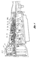
- Figure 1 shows the various clutches and bands with conventional abbreviations.
- Figure 2 shows, in schematic form, the torque flow paths for the transmission.
- the engine torque is transmitted to the housing of the torque converter pump or impeller 22.
- the converter impeller is a centrifugal pump which accelerates the fluid inside the torque converter towards the blades of turbine 24.
- the accelerated oil is then decelerated over the turbine blades.
- the oil at the turbine exit is redirected over the converter reactor back into the impeller, thereby achieving a torque multiplication effect.
- the torque is transmitted to overrunning coupling OWC1, which effects a torque reaction in the rotational direction of the engine.
- the coupling OWC1 overruns in the opposite direction.
- the engaged clutch CL3 carries torque from the centre shaft to the first of two simple planetary gear units of a Simpson gear set.
- the torque is delivered to the ring gear 30 and then is split into two components. One part is delivered over the planetary carrier 32 to the output shaft 34, which turns in the same rotational direction as the ring gear 30.
- the sun gear 36 carries the remaining part of the torque in the opposite direction to the rear gear set of the Simpson planetary gear set.
- the planetary carrier 38 of the rear planetary gear set is held by overrunning coupling OWC2.
- the torque delivered to the sun gear 42 is then transmitted over the planetaries to the ring gear 40, which reduces the velocity and multiplies the torque to the output shaft. This arrangement provides a 2.474 gear ratio.
- the torque flow is the same as in 1 st gear except that B2 is applied. With the engagement of B2, the sun gear speed is reduced to zero.
- the brake band (B2) then serves as a reaction element for the front planetary gear set and generates an output torque multiplication of 1.474 by holding 0.474 times engine torque as a reaction to the output.
- the output of the rear planetary gearset is zero since the sun gear 42 has zero speed (see Figure 2).
- the converter clutch 44 can be locked or unlocked in 2 nd gear depending on the driving condition.
- the coast clutch (CL1) is disengaged - i.e., electronically released - and free wheeling takes place since OWC1 overruns in coast mode (see Figure 2).
- This is the direct gear with a gear ratio of one. Since the gear change from 2 nd to 3 rd and from 3 rd to 2 nd has to be synchronised, more complex control functions are implemented for these gear changes.
- B1 In 4 th gear, B1 is applied and carries -.25 times engine torque as a reaction to the output. B1 decelerates the sun gear of the overdrive planetary gear set to zero speed and generates a gear ratio of .75. Engagement of CL1 is hydraulically inhibited and OWC1 overruns. Since B1 carries 0.25 times engine torque and since the overdrive planetary gear set is an input to the Simpson set, CL2 and CL3 are holding the 0.75 th fraction of engine torque. The gear ratio is 0.75.
- the converter clutch can be locked or unlocked based on the driving condition (see Figure 2.)
- the torque flow is the same as in 1 st gear in drive position except B3 and CL1 are applied to generate engine braking in coast mode.
- the converter clutch is hydraulically inhibited and cannot be applied electronically.
- B3 prevents overrunning of OWC2
- CL1 prevents overrunning of OWC1.
- the gear ratio is 2.474 (see Figure 2).
- the torque flow is the same as in 2 nd gear in drive position except CL1 is applied to achieve engine braking in coast mode. CL1 prevents overrunning of OWC1 in power OFF condition.
- the converter clutch control system has a dedicated hydraulic control system as well as a unique control strategy.
- the converter clutch is electronically controlled and can be engaged in each gear. Usually, the converter clutch will be locked starting in second gear, and it stays locked. By monitoring engine speed ⁇ N' and the turbine speed "NT", the state of the converter clutch or the amount of slip is determined.
- the converter clutch In order to be able to lock the converter clutch in each gear, the converter clutch must be modulated during a shift. It is then necessary to partially open the torque converter clutch during upshifts and downshifts in order to take advantage of the damping effect of the torque converter during a shift.
- the control system is able to adjust for the desired amount of differential speed during an upshift event or a downshift event. This requires a control system which is capable of adjusting capacity of the converter clutch.
- Converter clutch control systems for some known transmissions are partially electronically controlled (ON/OFF-solenoid) and are only capable of controlling the converter clutch in either “ON” or “OFF” states. This restricts the converter clutch operation only to operation in fourth or third gear.
- the converter clutch control system of the present invention can be operated as a simple ON/OFF system since the clutch capacity can be varied from 0% to 100%. It can also be operated, however, as a "full" modulated clutch with continuous slip under all operating conditions.
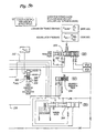
- the converter clutch can be controlled as a PWM-solenoid controlled converter clutch with a converter pressure modulator valve disposed between the PWM-solenoid and the converter clutch control valve as seen in Figures 5a-5b.
- the converter clutch control strategy will be described for each configuration. A brief description of the strategy has been set forth previously. The cooling system with a thermostat bypass valve system also will be described.
- control parameters for the complete control system of hardware configurations 1 and 2, including the control strategy:
- FIGS 5a and 5b we show an alternate torque converter clutch control system to that described in EP-A-0 707 165 that includes a converter clutch control valve 320, an additional converter pressure modulator valve system 322, a modified converter clutch accumulator valve 324, and a solenoid regulator valve 326.
- Figure 6 shows the converter control valve 320 and the cooler limit valve at 330 in enlarged form.
- Figure 7 shows a detailed view of the cooler limit valve.
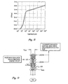
- the converter clutch accumulator valve 324 is shown in enlarged form in Figure 9.
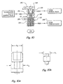
- the converter pressure modulator valve system 322 is shown in enlarged form in Figure 10.
- a pulse-width modulated solenoid valve 332 receives a PWM signal from the microcomputer controller 334 through signal lines 336.
- the pulse-width modulated valve 332 modulates SOL1 pressure in passage 338 and distributes a modulated pressure output through passage 340 to the converter pressure modulator valve 322.
- Line pressure in passage 342 is distributed to the converter pressure modulator valve system 322 from the manual valve 344. Passage 342 is pressurised when the manual valve is in the D, 3, 2 or 1 positions.
- valve system 322 comprises a valve spool having differential diameter lands and larger landing shown at 344 and the larger landing shown at 346.
- Valve spring 348 urges the valve spool in a downward direction. The upper end of the valve chamber in which the valve spool is disposed is exhausted, as shown at 350.
- the modulated pressure output of the valve system 322 is distributed to passage 352, which extends to the converter control valve 320.
- the modulated pressure in passage 352 acts on the differential area of lands 344 and 346 to complement the force of the spring 348.
- Pulse-width modulated pressure in passage 340 is distributed to a pilot valve 354, this valve is a single diameter valve, and acts on the lower end of the valve spool of the converter pressure modulator valve.
- the diameter of the pilot valve is less than the diameter of either land 344 or land 346.
- Exhaust port 356 is located directly adjacent land 346 and the output pressure port is located directly adjacent land 344.
- the converter control valve 320 comprises a valve spool 358 which has three lands 360, 362 and 364. Valve spool 358 is urged in a downward direction, as viewed in Figure 6, by valve spring 366. When it is in the position shown in Figure 6, valve spool 358 is seated on a valve plug 368 which is held in place by a wire retainer 370. Modulated pressure in passage 352 acts on the lower end of the valve spool to produce a force that oppose the force of the spring 366.
- Converter charge pressure in passage 372 communicates with converter clutch pressure passage 374 through the space between valve lands 360 and 362, thereby pressurising the converter clutch release side.
- Passage 376 communicates with the apply side of the converter clutch. It is pressurised by converter charge pressure from the release side of the converter clutch when the converter control valve 320 is in the downward position.
- the line pressure developed by pump 380 communicates with the main regulator valve through passage 382. Regulated output pressure is distributed to passage 372. Cooler flow in passage 384 is established as communication takes place between passage 372 and passage 376, depending on whether the converter clutch control valve 320 is in the upward or downward position. Modulated converter clutch pressure is established as passage 352 communicates with the converter clutch control valve 320, thus moving the control valve to its upward position. This connects the output passage 352 of the converter clutch apply side 376 and establishes converter clutch capacity.
- the output pressure of the converter clutch accumulator valve is distributed through passage 386, which communicates with the clutch release pressure in passage 374 through the space between lands 366 and 362.
- the pressure on the release side of the converter clutch is maintained at a constant value by the converter clutch accumulator valve 324 when the converter clutch is engaged.
- the input to the converter clutch accumulator valve is the converter charge pressure in passage 372.
- the converter clutch control valve spool is urged in a downward direction during reverse drive operation and during operation in manual low as selected by the manual valve.
- Thermostatic valve 328 includes an internal spring, shown at 394.
- the thermostatic valve transfer function for Figure 7 is plotted in Figure 8.
- the converter clutch accumulator valve is a pressure limiting valve with a feedback control. It is capable of maintaining a constant back pressure on the release side of the converter clutch regardless of a variable flow input. The ability to provide a constant back pressure with variable flow input enhances the converter clutch operation by achieving a constant back pressure on the clutch release side.
- the converter pressure modulator valve system is capable of accommodating high leakage oil flow, including leakage flow, out of the converter clutch apply side when the transmission oil temperatures are elevated. It is capable of maintaining the necessary apply pressure on the converter clutch apply side when the converter is commanded to be unlocked.
- the single diameter valve element 354 of the converter pressure modulator valve assembly makes it possible to calibrate the valve system for various engine applications without changing major hardware components (i.e., valve body machining) since it introduces a separate valve area that can be changed as desired for calibration purposes.
- the valve 354 thus acts as a pilot valve for the modulator valve.
- Figure 11 shows the converter clutch modulated pressure transfer function in a plot of PWM pressure against converter clutch modulated pressure.
- the converter clutch modulator pressure transfer function acts an amplifier for the PWM pressure developed by the PWM solenoid valve 332.
- the left-hand side of the plot of Figure 11 shows the PWM pressure transfer function with respect to the duty cycle of the PWM solenoid valve 332. It is plotted with two different input pressures; i.e., six bar maximum and four bar minimum.
- the relationship of PWM pressure versus converter clutch modulator pressure is shown in the transfer function plotted in Figure 11.
- the slopes of the pressures plotted in Figure 11 can be changed by changing a pilot valve diameter and by changing the spring load to adapt the system for various engine applications.
- the control strategy known as a torque feedforward system which is illustrated in Figure 5d of previously referenced EP-A-0 707 165, can be calibrated to accommodate the modification illustrated in the present Figure 5.
- the structure of the state model control block called "inverse valve model” can be adjusted in accordance with the slopes of the plots shown in Figure 11.
- the control block in Figure 5d of previously referenced EP-A-0 707 165 that is called "inverse PWM model” can be adjusted according to the maximum six bar input pressure described with reference to present Figure 5.
Landscapes
- Engineering & Computer Science (AREA)
- General Engineering & Computer Science (AREA)
- Mechanical Engineering (AREA)
- Control Of Transmission Device (AREA)
- Control Of Fluid Gearings (AREA)
- Hydraulic Clutches, Magnetic Clutches, Fluid Clutches, And Fluid Joints (AREA)
Claims (3)
- Commande automatique destinée à une transmission hydrocynétique à rapports multiples en vue de délivrer un couple provenant d'un moteur à un élément entraíné (34) comprenant un convertisseur de couple hydrocynétique et des engrenages de rapports multiples, ledit convertisseur de couple comprenant un impulseur (22) entraíné par ledit moteur et une turbine (24) reliée à un élément d'entrée de couple desdits engrenages, une partie de sortie de couple desdits engrenages étant reliée audit élément entraíné (34),ladite transmission comprenant des moyens d'embrayage et de frein mis en oeuvre par pression de fluide destinés à établir et à supprimer des variations de rapport de couple dans lesdits engrenages,ledit système de commande automatique comprenant,une source de pression, un système de vannes de commande reliant ladite source de pression auxdits moyens d'embrayage et de frein,un embrayage de dérivation de couple du convertisseur de couple à commande par pression (44) dans ledit convertisseur, ledit embrayage de dérivation (44) établissant un trajet d'écoulement de couple de friction entre ladite turbine (24) et ledit impulseur (22) lorsqu'il est appliqué, ledit embrayage de dérivation (44) comprenant un piston d'embrayage dans ledit convertisseur et définissant dans ledit convertisseur une chambre de pression de libération de l'embrayage de dérivation et une chambre de pression d'application de l'embrayage de dérivation,ledit piston d'embrayage étant mis en oeuvre avec un couple transmettant une capacité d'action qui dépend de la différence de pression de part et d'autre dudit piston d'embrayage,un passage de pression d'application de l'embrayage de dérivation (376) communiquant avec ledit convertisseur, un passage de pression de libération de l'embrayage de dérivation (374) communiquant avec ladite chambre de pression de libération,un moyen de vanne de régulateur de pression principale (378) dans ledit système de vannes destiné à réguler la pression de commande dans ledit système de vannes,un moyen de vanne d'accumulateur (324) dans ledit système de vannes communiquant avec ledit moyen de vanne de régulateur de pression principale (378) en vue d'établir une pression de seuil d'accumulateur dans ladite chambre de libération,un dispositif de refroidissement de fluide du convertisseur et un circuit de lubrification de la transmission comprenant un dispositif de refroidissement du convertisseur et des parties de lubrification,un moyen de vanne de commande de l'embrayage du convertisseur (320), mobile entre une première et une seconde positions, communiquant avec ledit passage de pression d'application (376) en vue de délivrer une pression dans ledit passage de pression d'application audit dispositif de refroidissement et audit circuit de lubrification lorsqu'il prend ladite première position, caractérisée parun moyen de vanne de modulateur de pression du convertisseur (322) communiquant avec ledit moyen de vanne de régulateur de pression principale (378) en vue de moduler ladite pression de commande pour produire une pression d'application de l'embrayage du convertisseur dans ledit passage de pression d'application de l'embrayage de dérivation (376) lorsque ledit moyen de vanne de commande de l'embrayage du convertisseur (320) prend ladite seconde position en vue de faire varier la différence de pression de part et d'autre dudit piston d'embrayage,un moyen d'électrovanne de pression du convertisseur (332) dans ledit système de vannes communiquant avec ledit moyen de vanne de modulateur (322) en vue d'établir une pression pilote sur ledit moyen de vanne de modulateur (322), etun moyen de commande électronique (334) sensible à des variables fonctionnelles en vue d'exciter ledit moyen d'électrovanne (332), grâce à quoi ladite capacité d'action de l'embrayage de dérivation est commandée pour réaliser une application et une libération sans à-coups.
- Commande automatique selon la revendication 1, dans laquelle lesdites variables fonctionnelles comprennent le régime du moteur, la vitesse de la turbine et la vitesse du véhicule, ledit moyen de commande à solénoïde (334) répondant auxdites variables pour réaliser une réduction commandée de la capacité d'action de l'embrayage de dérivation durant des changements de rapport dans lesdits engrenages.
- Commande automatique selon la revendication 1 ou 2, dans laquelle ledit système de vannes comprend un moyen de vanne d'accumulateur d'embrayage du convertisseur (324) communiquant avec ledit moyen de vanne de régulateur de pression principale (378) en vue d'établir une pression de libération constante de l'embrayage du convertisseur, ledit moyen de vanne d'accumulateur de l'embrayage du convertisseur communiquant avec la chambre de libération de pression de l'embrayage de dérivation par l'intermédiaire dudit moyen de vanne de commande de l'embrayage du convertisseur (320).
Applications Claiming Priority (2)
| Application Number | Priority Date | Filing Date | Title |
|---|---|---|---|
| US08/659,992 US5722519A (en) | 1994-10-14 | 1996-06-07 | Multiple ratio automatic transmission and torque converter |
| US659992 | 1996-06-07 |
Publications (3)
| Publication Number | Publication Date |
|---|---|
| EP0814285A2 EP0814285A2 (fr) | 1997-12-29 |
| EP0814285A3 EP0814285A3 (fr) | 1999-12-08 |
| EP0814285B1 true EP0814285B1 (fr) | 2003-07-23 |
Family
ID=24647676
Family Applications (1)
| Application Number | Title | Priority Date | Filing Date |
|---|---|---|---|
| EP97303939A Expired - Lifetime EP0814285B1 (fr) | 1996-06-07 | 1997-06-06 | Transmission automatique à plusiers vitesses et convertisseur de couple pontable |
Country Status (3)
| Country | Link |
|---|---|
| US (1) | US5722519A (fr) |
| EP (1) | EP0814285B1 (fr) |
| DE (1) | DE69723621T2 (fr) |
Families Citing this family (23)
| Publication number | Priority date | Publication date | Assignee | Title |
|---|---|---|---|---|
| JP3277850B2 (ja) * | 1997-07-09 | 2002-04-22 | 日産自動車株式会社 | トロイダル型無段変速機の油圧制御装置 |
| US6292731B1 (en) | 1998-07-27 | 2001-09-18 | Ford Global Technologies, Inc. | Automatic shift control system for an automatic transmission including a select-shift manual control |
| DE10005086A1 (de) * | 2000-02-04 | 2001-08-09 | Zahnradfabrik Friedrichshafen | Getriebe mit zentraler Kupplungsausrückung |
| US6301538B1 (en) | 2000-06-07 | 2001-10-09 | Ford Global Technologies, Inc. | Swap shift multiple-ratio automatic transmission |
| US6278926B1 (en) | 2000-09-18 | 2001-08-21 | Ford Global Technologies, Inc. | Adaptive electronic transmission control system and strategy for nonsynchronous automatic transmission |
| US6449548B1 (en) | 2001-02-14 | 2002-09-10 | Ford Global Technologies, Inc. | Automatic transmission shift control |
| EP1353095A1 (fr) * | 2002-04-10 | 2003-10-15 | Van Doorne's Transmissie B.V. | Méthode de commande pour une transmission automatique |
| US20050107937A1 (en) * | 2002-04-10 | 2005-05-19 | Luk Lamellen Und Kupplungsbau Beteiligungs Kg | Transmission control system and method for compensating roadway changes in a transmission control system of an automatic vehicle transmission |
| DE10256107A1 (de) * | 2002-11-29 | 2004-08-12 | Audi Ag | Verfahren und Vorrichtung zur Schätzung des Brennraumdrucks |
| US6961646B2 (en) * | 2003-10-31 | 2005-11-01 | Ford Global Technologies, Llc | Automatic transmission control system with direct electronic swap-shift control |
| US7107135B2 (en) * | 2003-10-31 | 2006-09-12 | Ford Global Technologies, Llc | Auxiliary gearset shift progression command generator for a swap-shift automatic transmission |
| US6994647B2 (en) * | 2003-11-13 | 2006-02-07 | Ford Global Technologies, Llc | Adaptive pressure control method for achieving synchronous upshifts in a multiple-ratio transmission |
| US7115069B2 (en) * | 2003-11-13 | 2006-10-03 | Ford Global Technologies, Llc | Electronic adaptive swap-shift control for an automatic transmission for automotive vehicles |
| US7216025B2 (en) * | 2003-11-13 | 2007-05-08 | Ford Global Technologies, Llc | Adaptive pressure control method for synchronous downshifts in a multiple-ratio transmission |
| US7287444B2 (en) * | 2004-06-01 | 2007-10-30 | Electronic Systems Eliminator, Inc. | Transmission pressure modulation by orificed check valve |
| ATE540244T1 (de) * | 2004-08-20 | 2012-01-15 | Nt Consulting Int Pty Ltd | Drehmomentwandler |
| AU2005274687B2 (en) * | 2004-08-20 | 2010-11-25 | Nt Consulting International Pty Ltd | Torque converter |
| US6978201B1 (en) * | 2004-12-22 | 2005-12-20 | Daimlerchrysler Corporation | Model based kickdown shift method for clutch to clutch shift transmissions with accumulators |
| US7217222B2 (en) * | 2005-04-05 | 2007-05-15 | Ford Global Technologies, Llc | Method and system for inferring and controlling transmission fluid temperature |
| EP2085660A1 (fr) * | 2008-02-01 | 2009-08-05 | GM Global Technology Operations, Inc. | Processus d'étalonnage de transmission automatique |
| US8464851B2 (en) * | 2011-04-04 | 2013-06-18 | GM Global Technology Operations LLC | Electro-hydraulic control system for an automatic transmission |
| US8651240B1 (en) | 2012-12-24 | 2014-02-18 | United Technologies Corporation | Pressurized reserve lubrication system for a gas turbine engine |
| RU2737454C1 (ru) * | 2020-01-20 | 2020-11-30 | Федеральное государственное бюджетное образовательное учреждение высшего образования "Курганский государственный университет" | Система переключения передач без разрыва потока мощности |
Family Cites Families (20)
| Publication number | Priority date | Publication date | Assignee | Title |
|---|---|---|---|---|
| JPS5517258B2 (fr) * | 1971-10-12 | 1980-05-10 | ||
| US4468988A (en) * | 1980-08-04 | 1984-09-04 | Mitsubishi Jidosha Kogyo Kabushiki Kaisha | Slip control system for a clutch |
| JPS59133865A (ja) * | 1983-01-19 | 1984-08-01 | Honda Motor Co Ltd | 車両用自動変速装置 |
| US4725951A (en) * | 1983-12-29 | 1988-02-16 | Nissan Motor Co., Ltd. | Control system for lock-up clutch in torque converter |
| JPH0621649B2 (ja) * | 1983-12-30 | 1994-03-23 | アイシン・エィ・ダブリュ株式会社 | 車両用自動変速機の流体継手のロツクアツプクラツチ制御装置 |
| US4706790A (en) * | 1986-07-17 | 1987-11-17 | General Motors Corporation | Gain scheduling technique for a closed loop slip control system |
| US4975845A (en) * | 1988-04-29 | 1990-12-04 | Chrysler Corporation | Method of operating an electronic automatic transmission system |
| JPH0745906B2 (ja) * | 1988-10-31 | 1995-05-17 | マツダ株式会社 | 流体継手のスリップ制御装置 |
| US5029087A (en) * | 1989-07-24 | 1991-07-02 | Ford Motor Company | Electronic control system for controlling torque converter bypass clutches |
| DE69112109T2 (de) * | 1990-04-18 | 1996-04-18 | Mazda Motor | Steuerungssystem für ein Momentwandler. |
| US5157608A (en) * | 1990-09-14 | 1992-10-20 | Ford Motor Company | Electronic control system for multiple ratio transmission including circuit pressure control |
| US5081886A (en) * | 1990-09-14 | 1992-01-21 | Ford Motor Company | Automatic transaxle control system for an automotive vehicle |
| US5150297A (en) * | 1990-09-17 | 1992-09-22 | Ford Motor Company | Electronic shift controls for a multiple ratio transaxle |
| US5123302A (en) * | 1990-12-24 | 1992-06-23 | Ford Motor Company | Automatic transmission gearshift control having feedforward response of clutch and its hydraulic actuation |
| US5121820A (en) * | 1990-12-24 | 1992-06-16 | Ford Motor Company | Feedforward control for automatic transmission torque converter bypass clutch slip |
| US5305663A (en) * | 1992-08-10 | 1994-04-26 | Ford Motor Company | Automatic transmission control system |
| US5303616A (en) * | 1992-08-10 | 1994-04-19 | Ford Motor Company | Electronically controlled bypass clutch based on percent-shift-completion for a torque converter |
| US5272630A (en) * | 1992-09-15 | 1993-12-21 | Ford Motor Company | Automatic transmission control and strategy for neutral idle |
| US5315901A (en) * | 1992-12-17 | 1994-05-31 | Ford Motor Company | Automatic transmission with a modulated pressure converter bypass clutch priority valve circuit |
| US5553694A (en) * | 1994-10-14 | 1996-09-10 | Ford Motor Company | Multiple ratio automatic transmission and torque converter |
-
1996
- 1996-06-07 US US08/659,992 patent/US5722519A/en not_active Expired - Lifetime
-
1997
- 1997-06-06 DE DE69723621T patent/DE69723621T2/de not_active Expired - Lifetime
- 1997-06-06 EP EP97303939A patent/EP0814285B1/fr not_active Expired - Lifetime
Also Published As
| Publication number | Publication date |
|---|---|
| DE69723621T2 (de) | 2004-01-22 |
| US5722519A (en) | 1998-03-03 |
| EP0814285A3 (fr) | 1999-12-08 |
| DE69723621D1 (de) | 2003-08-28 |
| EP0814285A2 (fr) | 1997-12-29 |
Similar Documents
| Publication | Publication Date | Title |
|---|---|---|
| EP0707165B1 (fr) | Transmission automatique à plusieurs vitesses avec convertisseur de couple | |
| US5722519A (en) | Multiple ratio automatic transmission and torque converter | |
| US4637281A (en) | Control valve system for a four-speed automatic power transmission transaxle | |
| EP0978672B1 (fr) | Système de commande pour transmission automatique à plusieurs vitesses | |
| US4527448A (en) | Hydraulic control system for electronic transmission control | |
| EP0635662B1 (fr) | Transmission automatique à commande électronique avec régulation de pression à sûreté intégrée | |
| US5413539A (en) | Control system for controlling engagement of an automatic transmission torque converter clutch | |
| US4476747A (en) | Timing control valve in automatic transmission control apparatus | |
| US5005444A (en) | Hydraulic control apparatus for automatic transmission for motor vehicle | |
| EP0626528B1 (fr) | Boíte de vitesse automatique | |
| EP0770800B1 (fr) | Une transmission automatique | |
| US4880090A (en) | Hydraulic controlling system for lockup clutches | |
| EP0210485B1 (fr) | Système de valves de contrôle pour une transmission automatique à quatre vitesses, comprenant une valve régulatrice à deux gammes pour contrôler indépendamment deux changements de vitesse vers le haut | |
| US4665770A (en) | Control system for a multiple ratio transmission having a lockup clutch torque converter | |
| US5083481A (en) | Electronically controlled automatic transmission | |
| US5342253A (en) | Automatic transmission control system | |
| US6301538B1 (en) | Swap shift multiple-ratio automatic transmission | |
| EP0707163B1 (fr) | Système de commande de changement de vitesse pour une transmission automatique à plusieurs vitesses avec des gammes de vitesse manuelles | |
| US5315901A (en) | Automatic transmission with a modulated pressure converter bypass clutch priority valve circuit | |
| US6171211B1 (en) | Automatic transmission control system having a neutral idle feature | |
| US5399131A (en) | Automatic transmission control system having two accumulators for four clutches controlled by a single accumulator back pressure valve | |
| US5409427A (en) | Automatic transmission control system | |
| US5366420A (en) | Automatic transmission control system | |
| US6622835B2 (en) | Engagement control having a multiplexed hydraulic circuit for controlling a torque converter clutch and shifting clutches in an automatic transmission | |
| EP0933562B1 (fr) | Système de commande d'engagement de vitesse avant ou arrière pour transmission automatique à plusieurs vitesses |
Legal Events
| Date | Code | Title | Description |
|---|---|---|---|
| PUAI | Public reference made under article 153(3) epc to a published international application that has entered the european phase |
Free format text: ORIGINAL CODE: 0009012 |
|
| AK | Designated contracting states |
Kind code of ref document: A2 Designated state(s): DE FR GB |
|
| RIN1 | Information on inventor provided before grant (corrected) |
Inventor name: WICKLER, WOLFGANG Inventor name: WAGNER, THOMAS Inventor name: CROONEN, WERNER Inventor name: REICHERT, ERIC Inventor name: MARTIN, THOMAS Inventor name: KIRCHHOFFER, JOHANN |
|
| PUAL | Search report despatched |
Free format text: ORIGINAL CODE: 0009013 |
|
| AK | Designated contracting states |
Kind code of ref document: A3 Designated state(s): AT BE CH DE DK ES FI FR GB GR IE IT LI LU MC NL PT SE |
|
| 17P | Request for examination filed |
Effective date: 20000506 |
|
| AKX | Designation fees paid |
Free format text: DE FR GB |
|
| 17Q | First examination report despatched |
Effective date: 20011113 |
|
| GRAH | Despatch of communication of intention to grant a patent |
Free format text: ORIGINAL CODE: EPIDOS IGRA |
|
| GRAH | Despatch of communication of intention to grant a patent |
Free format text: ORIGINAL CODE: EPIDOS IGRA |
|
| GRAA | (expected) grant |
Free format text: ORIGINAL CODE: 0009210 |
|
| AK | Designated contracting states |
Designated state(s): DE FR GB |
|
| REG | Reference to a national code |
Ref country code: GB Ref legal event code: FG4D |
|
| REF | Corresponds to: |
Ref document number: 69723621 Country of ref document: DE Date of ref document: 20030828 Kind code of ref document: P |
|
| ET | Fr: translation filed | ||
| PLBE | No opposition filed within time limit |
Free format text: ORIGINAL CODE: 0009261 |
|
| STAA | Information on the status of an ep patent application or granted ep patent |
Free format text: STATUS: NO OPPOSITION FILED WITHIN TIME LIMIT |
|
| 26N | No opposition filed |
Effective date: 20040426 |
|
| REG | Reference to a national code |
Ref country code: FR Ref legal event code: TP |
|
| REG | Reference to a national code |
Ref country code: DE Ref legal event code: R082 Ref document number: 69723621 Country of ref document: DE Representative=s name: DOERFLER, THOMAS, DR.-ING., DE |
|
| REG | Reference to a national code |
Ref country code: FR Ref legal event code: PLFP Year of fee payment: 20 |
|
| PGFP | Annual fee paid to national office [announced via postgrant information from national office to epo] |
Ref country code: GB Payment date: 20160525 Year of fee payment: 20 |
|
| PGFP | Annual fee paid to national office [announced via postgrant information from national office to epo] |
Ref country code: FR Payment date: 20160531 Year of fee payment: 20 |
|
| PGFP | Annual fee paid to national office [announced via postgrant information from national office to epo] |
Ref country code: DE Payment date: 20160629 Year of fee payment: 20 |
|
| REG | Reference to a national code |
Ref country code: DE Ref legal event code: R071 Ref document number: 69723621 Country of ref document: DE |
|
| REG | Reference to a national code |
Ref country code: GB Ref legal event code: PE20 Expiry date: 20170605 |
|
| PG25 | Lapsed in a contracting state [announced via postgrant information from national office to epo] |
Ref country code: GB Free format text: LAPSE BECAUSE OF EXPIRATION OF PROTECTION Effective date: 20170605 |