EP0814533A2 - Antenne directionnelle pour radiotéléphone - Google Patents
Antenne directionnelle pour radiotéléphone Download PDFInfo
- Publication number
- EP0814533A2 EP0814533A2 EP97110081A EP97110081A EP0814533A2 EP 0814533 A2 EP0814533 A2 EP 0814533A2 EP 97110081 A EP97110081 A EP 97110081A EP 97110081 A EP97110081 A EP 97110081A EP 0814533 A2 EP0814533 A2 EP 0814533A2
- Authority
- EP
- European Patent Office
- Prior art keywords
- antenna
- directional antenna
- lens
- directional
- conductor
- Prior art date
- Legal status (The legal status is an assumption and is not a legal conclusion. Google has not performed a legal analysis and makes no representation as to the accuracy of the status listed.)
- Withdrawn
Links
Images

Classifications
-
- H—ELECTRICITY
- H01—ELECTRIC ELEMENTS
- H01Q—ANTENNAS, i.e. RADIO AERIALS
- H01Q19/00—Combinations of primary active antenna elements and units with secondary devices, e.g. with quasi-optical devices, for giving the antenna a desired directional characteristic
- H01Q19/06—Combinations of primary active antenna elements and units with secondary devices, e.g. with quasi-optical devices, for giving the antenna a desired directional characteristic using refracting or diffracting devices, e.g. lens
-
- H—ELECTRICITY
- H01—ELECTRIC ELEMENTS
- H01Q—ANTENNAS, i.e. RADIO AERIALS
- H01Q1/00—Details of, or arrangements associated with, antennas
- H01Q1/12—Supports; Mounting means
- H01Q1/22—Supports; Mounting means by structural association with other equipment or articles
- H01Q1/24—Supports; Mounting means by structural association with other equipment or articles with receiving set
- H01Q1/241—Supports; Mounting means by structural association with other equipment or articles with receiving set used in mobile communications, e.g. GSM
- H01Q1/242—Supports; Mounting means by structural association with other equipment or articles with receiving set used in mobile communications, e.g. GSM specially adapted for hand-held use
- H01Q1/243—Supports; Mounting means by structural association with other equipment or articles with receiving set used in mobile communications, e.g. GSM specially adapted for hand-held use with built-in antennas
-
- H—ELECTRICITY
- H04—ELECTRIC COMMUNICATION TECHNIQUE
- H04B—TRANSMISSION
- H04B1/00—Details of transmission systems, not covered by a single one of groups H04B3/00 - H04B13/00; Details of transmission systems not characterised by the medium used for transmission
- H04B1/38—Transceivers, i.e. devices in which transmitter and receiver form a structural unit and in which at least one part is used for functions of transmitting and receiving
- H04B1/3827—Portable transceivers
Definitions
- electromagnetic radiation from the antenna causes bio- / magnetic interactions with the user of a telephone.
- the antenna In contrast to car telephones, in which the antenna is shielded from the user by the body, the antenna is in the usual portable radio telephones in close proximity to the ear canal and the brain of the user.
- the electromagnetic radiation causes a resonance of water molecules, so that the affected parts of the body could warm up. This could be harmful to humans.
- DE-OS 31 18 818 A1 describes a microwave directional antenna with line emitters. that radiates in two directions.
- the use of waveguide slot antennas is proposed as a line radiator, the beams being focused by dielectric lenses located outside the line radiator.
- a line source is arranged in the focal line of the dielectric lens. The arrangement results in a narrow beam due to the focusing by the lens.
- as large a radiation area as possible should be detected in mobile radio telephones, only the head region of the cell phone user being to be excluded.
- DE-OS 31 35 818 A1 is a cavity resonator for use both as an antenna and a transmitter with one slotted waveguide described. Depending on the frequency, it is recommended to provide a center conductor.
- the antenna is used as a transmit / receive antenna and is therefore basically suitable for mobile phones.
- Such a slot antenna is also found in the Taschenbuch der Hochfrequenztechnik "by Meinke, Gundlach, edited by K. Lange and K.-H. Löcherer, Volume 2, Springer Verlag Berlin / Heidelberg, 1992, page N17, chapter
- the diameter and the slot length depend on the wavelength.
- the opening angle for the mobile radio area should be as large as possible to ensure a good connection which is independent of the position of the user.
- the size must be small enough to meet the ergonomic requirements for portable radio telephones. This is not the case with conventional antenna shapes. Because of the small distance between the antenna of a portable radio telephone and the head of a user, the user must be protected from the influence of the near fields by a directivity of the antenna.
- the object of the invention was therefore to provide a directional antenna for directional radiation of electromagnetic waves, which protects against biological / magnetic interactions in the potentially endangered head area and ensures reliable operation of the radio telephones.
- the directional antenna should be compact so that it can be used in portable radio telephones.
- the directional antenna should therefore have a line resonator, which consists of an inner conductor and an outer conductor, which surrounds the inner conductor.
- the directional antenna is fed on one or both ends of the inner conductor.
- the object is achieved by the directional antenna according to claim 1.
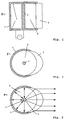
- the directional antenna 1 essentially consists of a line resonator 2 with an inner conductor 3 and an outer conductor 4.
- the outer conductor 4 has upper and lower end faces and thus represents a resonator body certain sector open. It thus allows electromagnetic waves to be emitted in a given direction.
- a delay lens 5 is introduced into the opening of the outer conductor 4. It causes an additional bundling of the emitted waves.
- FIG. 2 shows the preferred embodiment of the directional antenna 1 in a coaxial, round shape.
- the delay lens 5 has a concave shape on its outer surface.
- the inner surface of the delay lens is circular, shaped according to the circumference of the outer conductor 4.
- the beam path of the directional antenna 1 is shown in FIG. 3. While the waves in the interior of the resonator body 4 reflect between the latter and the inner conductor, the waves which radiate onto the opening of the outer conductor 4 are brought into a parallel, directed beam by the delay lens 5. The space behind the resonator body 4 is radiation-free. In the case of a portable radio telephone, the antenna would therefore have to be oriented such that the user's head is behind the resonator body 4 and the rays are directed away from the head by the delay lens 5.
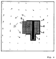
- the characteristics of the directional antenna 1 can be seen from FIGS. 4 and 5.
- FIG. 4 shows the field strength in the vicinity of the antenna. Similar to FIG. 1, the antenna is shown in longitudinal section. The field strength is proportional to the length of the arrows. The large arrows show that the field strength is greatest in the area of the delay lens 5. On the right side of the illustration, behind the outer conductor 4, the field strength is negligible.
- FIG. 5 shows the relative electric field strength at a distance of one meter from the antenna.
- resonator height i.e. the height of the outer conductor 4
- the resonator diameter i.e. the diameter of the outer conductor 4 is also a multiple of half the wavelength of the waves in the dielectric 6.
- the field strength in the range from 90 ° to 270 ° in the clockwise direction is relatively large.
- the field strength is only 0.2 times the field strength of the opposite area (at 0 °).
- the antenna is therefore suitable for considerably reducing the harmful radiation in the area of the head of a telephone user.
Landscapes
- Engineering & Computer Science (AREA)
- Computer Networks & Wireless Communication (AREA)
- Signal Processing (AREA)
- Aerials With Secondary Devices (AREA)
- Variable-Direction Aerials And Aerial Arrays (AREA)
Applications Claiming Priority (2)
| Application Number | Priority Date | Filing Date | Title |
|---|---|---|---|
| DE19624745A DE19624745A1 (de) | 1996-06-21 | 1996-06-21 | Richtantenne für Mikrowellenfunktelefone |
| DE19624745 | 1996-06-21 |
Publications (2)
| Publication Number | Publication Date |
|---|---|
| EP0814533A2 true EP0814533A2 (fr) | 1997-12-29 |
| EP0814533A3 EP0814533A3 (fr) | 2000-05-03 |
Family
ID=7797551
Family Applications (1)
| Application Number | Title | Priority Date | Filing Date |
|---|---|---|---|
| EP97110081A Withdrawn EP0814533A3 (fr) | 1996-06-21 | 1997-06-20 | Antenne directionnelle pour radiotéléphone |
Country Status (2)
| Country | Link |
|---|---|
| EP (1) | EP0814533A3 (fr) |
| DE (1) | DE19624745A1 (fr) |
Cited By (1)
| Publication number | Priority date | Publication date | Assignee | Title |
|---|---|---|---|---|
| WO2004062034A1 (fr) * | 2002-12-25 | 2004-07-22 | Nec Corporation | Téléphone portable |
Families Citing this family (2)
| Publication number | Priority date | Publication date | Assignee | Title |
|---|---|---|---|---|
| DE19815322A1 (de) * | 1998-04-06 | 1999-10-07 | Kreitmair Steck Wolfgang | Reflektorantenne für analoge und digitale mobile Telefone (GSM, DECT, UMTS etc.) |
| DE10137440A1 (de) * | 2001-07-31 | 2003-02-13 | Max Michael Schlereth | Informationsempfangseinrichtungen und Verfahren zum Empfangen von Informationen über ein bestimmtes Objekt |
Family Cites Families (14)
| Publication number | Priority date | Publication date | Assignee | Title |
|---|---|---|---|---|
| NL71623C (fr) * | 1945-08-25 | |||
| DE931604C (de) * | 1952-06-01 | 1955-08-11 | Pintsch Electro G M B H | Richtantenne, vorzugsweise fuer Dezimeterwellen |
| US4042935A (en) * | 1974-08-01 | 1977-08-16 | Hughes Aircraft Company | Wideband multiplexing antenna feed employing cavity backed wing dipoles |
| US4148035A (en) * | 1977-12-14 | 1979-04-03 | Rca Corp. | Subwavelength monopulse antenna |
| US4318103A (en) * | 1980-03-17 | 1982-03-02 | Comgeneral Corporation | Compact radar detector and range extender |
| DE3118745A1 (de) * | 1981-05-12 | 1982-12-02 | Licentia Patent-Verwaltungs-Gmbh, 6000 Frankfurt | Mikrowellenantenne fuer linienverbindungen, insbesondere im millimeterwellenbereich |
| DE3135818A1 (de) * | 1981-09-10 | 1983-03-24 | Robert Bosch Gmbh, 7000 Stuttgart | Hohlraumresonator |
| EP0217426A3 (fr) * | 1985-08-08 | 1988-07-13 | The Secretary of State for Defence in Her Britannic Majesty's Government of the United Kingdom of Great Britain and | Dispositif d'antenne microbande |
| GB2212665B (en) * | 1987-11-23 | 1991-09-04 | Gen Electric Co Plc | A slot antenna |
| JPH03228407A (ja) * | 1989-12-11 | 1991-10-09 | Nec Corp | アンテナおよび該アンテナを用いた携帯用無線機 |
| DE4221121C1 (de) * | 1992-06-26 | 1993-10-21 | Siemens Ag | Handfunkgerät |
| US5335366A (en) * | 1993-02-01 | 1994-08-02 | Daniels John J | Radiation shielding apparatus for a radio transmitting device |
| GB2276494A (en) * | 1993-03-24 | 1994-09-28 | Mcgrath James Joseph | Mobile telephone shield. |
| US5373304A (en) * | 1993-05-27 | 1994-12-13 | Nolan; James F. | Cellular phone antenna reflector |
-
1996
- 1996-06-21 DE DE19624745A patent/DE19624745A1/de not_active Withdrawn
-
1997
- 1997-06-20 EP EP97110081A patent/EP0814533A3/fr not_active Withdrawn
Cited By (1)
| Publication number | Priority date | Publication date | Assignee | Title |
|---|---|---|---|---|
| WO2004062034A1 (fr) * | 2002-12-25 | 2004-07-22 | Nec Corporation | Téléphone portable |
Also Published As
| Publication number | Publication date |
|---|---|
| DE19624745A1 (de) | 1998-01-02 |
| EP0814533A3 (fr) | 2000-05-03 |
Similar Documents
| Publication | Publication Date | Title |
|---|---|---|
| DE69619453T2 (de) | Einrichtung zur Verbindung eines Radiotelefonapparates mit einer aussenliegenden Antenne | |
| DE69929614T2 (de) | Antenneneinspeisung, reflektorantennensystem und rauscharmer empfänger mit entsprechender antennenspeisung | |
| DE1245447B (de) | Richtantenne mit Ringfokus-Paraboloidreflektor | |
| WO1987003143A1 (fr) | Antenne en cornet | |
| DE60014218T2 (de) | Hornantenne für zwei Frequenzen mit Apertursperrtöpfen mit zwei Tiefen zum Ausgleichen von Richtcharakteristiken in E- und H- Ebene | |
| DE102009054526A1 (de) | Dielektrisch belastete Antenne mit innerem Hohlraumabschnitt | |
| EP1619747A1 (fr) | Antenne parabolique de détecteur de niveau et détecteur de niveau comportant une antenne parabolique | |
| DE69608540T2 (de) | Tragbares funkgerät mit einer strahlungsabschirmrnden antennenvorrichtung | |
| EP0652645A1 (fr) | Appareil radio portable muni de moyens pour protéger l'utilisateur contre le rayonnement | |
| DE1020070B (de) | Einrichtung mit einem Hohlleiter mit rechteckigem Querschnitt zur UEbertragung senkrecht zueinander polarisierter Wellen | |
| DE69015460T2 (de) | Ineinandergeschachtelte Anordnung von Hornstrahlern. | |
| DE2746376C2 (de) | Koppelvorrichtung zwischen einer Koaxialleitung und einem Hohlleiter | |
| EP0902499A1 (fr) | Cable coaxial haute fréquence rayonnant | |
| EP0814533A2 (fr) | Antenne directionnelle pour radiotéléphone | |
| DE102018211422A1 (de) | Füllstandradarantennenanordnung zur Messung eines Füllstandes in einem Behälter | |
| DE69420368T2 (de) | Bikonischer Mehrmodenresonator | |
| DE19961237A1 (de) | Antenne zur Abstrahlung und zum Empfang elektromagnetischer Wellen | |
| DE102014112487A1 (de) | Gruppenantenne aus hornstrahlern mit dielektrischer abdeckung | |
| DE2039714A1 (de) | Koaxialfilter | |
| EP0122391B1 (fr) | Antenne à large bande à micro-ondes | |
| DE888423C (de) | Anordnung zum Senden und/oder Empfangen ultrahochfrequenter elektrischer Schwingungen des Dezimeter- oder Zentimeterwellenlaengengebietes | |
| EP0898323A2 (fr) | Aiguillage de polarisation pour deux bandes de fréquence différentes | |
| DE3735226C2 (fr) | ||
| DE102014112485A1 (de) | Hornstrahlerantenne mit verringerter verkopplung zwischen antennenelementen | |
| EP0034810A1 (fr) | Antenne directionnelle pour hyperfréquences ayant un lobe principal en forme d'un secteur sphérique |
Legal Events
| Date | Code | Title | Description |
|---|---|---|---|
| PUAI | Public reference made under article 153(3) epc to a published international application that has entered the european phase |
Free format text: ORIGINAL CODE: 0009012 |
|
| AK | Designated contracting states |
Kind code of ref document: A2 Designated state(s): AT BE CH DE DK ES FI FR GB GR IE IT LI LU MC NL PT SE |
|
| PUAL | Search report despatched |
Free format text: ORIGINAL CODE: 0009013 |
|
| AK | Designated contracting states |
Kind code of ref document: A3 Designated state(s): AT BE CH DE DK ES FI FR GB GR IE IT LI LU MC NL PT SE |
|
| STAA | Information on the status of an ep patent application or granted ep patent |
Free format text: STATUS: THE APPLICATION IS DEEMED TO BE WITHDRAWN |
|
| 18D | Application deemed to be withdrawn |
Effective date: 20000101 |