EP0814948B1 - Procede de production d'un corps moule par soufflage presentant des dimensions multiples et dispositif permettant d'appliquer ledit procede - Google Patents
Procede de production d'un corps moule par soufflage presentant des dimensions multiples et dispositif permettant d'appliquer ledit procede Download PDFInfo
- Publication number
- EP0814948B1 EP0814948B1 EP96907361A EP96907361A EP0814948B1 EP 0814948 B1 EP0814948 B1 EP 0814948B1 EP 96907361 A EP96907361 A EP 96907361A EP 96907361 A EP96907361 A EP 96907361A EP 0814948 B1 EP0814948 B1 EP 0814948B1
- Authority
- EP
- European Patent Office
- Prior art keywords
- tubular component
- shaping unit
- extrusion
- mold
- tubular
- Prior art date
- Legal status (The legal status is an assumption and is not a legal conclusion. Google has not performed a legal analysis and makes no representation as to the accuracy of the status listed.)
- Expired - Lifetime
Links
- 238000004519 manufacturing process Methods 0.000 title claims abstract description 6
- 238000000034 method Methods 0.000 title claims description 28
- 238000007493 shaping process Methods 0.000 claims abstract description 36
- 238000001125 extrusion Methods 0.000 claims abstract description 26
- 238000000071 blow moulding Methods 0.000 claims abstract description 5
- 230000008021 deposition Effects 0.000 claims abstract description 5
- 238000002347 injection Methods 0.000 claims abstract 4
- 239000007924 injection Substances 0.000 claims abstract 4
- 230000000295 complement effect Effects 0.000 claims description 4
- 238000000151 deposition Methods 0.000 description 4
- 239000002699 waste material Substances 0.000 description 4
- 239000000463 material Substances 0.000 description 2
- 238000007789 sealing Methods 0.000 description 2
- 206010011416 Croup infectious Diseases 0.000 description 1
- 230000006978 adaptation Effects 0.000 description 1
- 210000000080 chela (arthropods) Anatomy 0.000 description 1
- 238000006243 chemical reaction Methods 0.000 description 1
- 239000004020 conductor Substances 0.000 description 1
- 238000001816 cooling Methods 0.000 description 1
- 238000005520 cutting process Methods 0.000 description 1
- 230000005611 electricity Effects 0.000 description 1
- 230000002349 favourable effect Effects 0.000 description 1
- 230000005484 gravity Effects 0.000 description 1
- 238000003780 insertion Methods 0.000 description 1
- 230000037431 insertion Effects 0.000 description 1
- 239000007769 metal material Substances 0.000 description 1
- 238000002156 mixing Methods 0.000 description 1
- 238000000465 moulding Methods 0.000 description 1
- 238000011282 treatment Methods 0.000 description 1
- 238000009423 ventilation Methods 0.000 description 1
Images


Classifications
-
- B—PERFORMING OPERATIONS; TRANSPORTING
- B29—WORKING OF PLASTICS; WORKING OF SUBSTANCES IN A PLASTIC STATE IN GENERAL
- B29C—SHAPING OR JOINING OF PLASTICS; SHAPING OF MATERIAL IN A PLASTIC STATE, NOT OTHERWISE PROVIDED FOR; AFTER-TREATMENT OF THE SHAPED PRODUCTS, e.g. REPAIRING
- B29C53/00—Shaping by bending, folding, twisting, straightening or flattening; Apparatus therefor
- B29C53/02—Bending or folding
- B29C53/08—Bending or folding of tubes or other profiled members
- B29C53/083—Bending or folding of tubes or other profiled members bending longitudinally, i.e. modifying the curvature of the tube axis
-
- B—PERFORMING OPERATIONS; TRANSPORTING
- B29—WORKING OF PLASTICS; WORKING OF SUBSTANCES IN A PLASTIC STATE IN GENERAL
- B29C—SHAPING OR JOINING OF PLASTICS; SHAPING OF MATERIAL IN A PLASTIC STATE, NOT OTHERWISE PROVIDED FOR; AFTER-TREATMENT OF THE SHAPED PRODUCTS, e.g. REPAIRING
- B29C31/00—Handling, e.g. feeding of the material to be shaped, storage of plastics material before moulding; Automation, i.e. automated handling lines in plastics processing plants, e.g. using manipulators or robots
- B29C31/04—Feeding of the material to be moulded, e.g. into a mould cavity
- B29C31/08—Feeding of the material to be moulded, e.g. into a mould cavity of preforms to be moulded, e.g. tablets, fibre reinforced preforms, extruded ribbons, tubes or profiles; Manipulating means specially adapted for feeding preforms, e.g. supports conveyors
-
- B—PERFORMING OPERATIONS; TRANSPORTING
- B29—WORKING OF PLASTICS; WORKING OF SUBSTANCES IN A PLASTIC STATE IN GENERAL
- B29C—SHAPING OR JOINING OF PLASTICS; SHAPING OF MATERIAL IN A PLASTIC STATE, NOT OTHERWISE PROVIDED FOR; AFTER-TREATMENT OF THE SHAPED PRODUCTS, e.g. REPAIRING
- B29C49/00—Blow-moulding, i.e. blowing a preform or parison to a desired shape within a mould; Apparatus therefor
- B29C49/02—Combined blow-moulding and manufacture of the preform or the parison
- B29C49/04—Extrusion blow-moulding
-
- B—PERFORMING OPERATIONS; TRANSPORTING
- B29—WORKING OF PLASTICS; WORKING OF SUBSTANCES IN A PLASTIC STATE IN GENERAL
- B29C—SHAPING OR JOINING OF PLASTICS; SHAPING OF MATERIAL IN A PLASTIC STATE, NOT OTHERWISE PROVIDED FOR; AFTER-TREATMENT OF THE SHAPED PRODUCTS, e.g. REPAIRING
- B29C49/00—Blow-moulding, i.e. blowing a preform or parison to a desired shape within a mould; Apparatus therefor
- B29C49/42—Component parts, details or accessories; Auxiliary operations
- B29C49/4242—Means for deforming the parison prior to the blowing operation
-
- B—PERFORMING OPERATIONS; TRANSPORTING
- B29—WORKING OF PLASTICS; WORKING OF SUBSTANCES IN A PLASTIC STATE IN GENERAL
- B29C—SHAPING OR JOINING OF PLASTICS; SHAPING OF MATERIAL IN A PLASTIC STATE, NOT OTHERWISE PROVIDED FOR; AFTER-TREATMENT OF THE SHAPED PRODUCTS, e.g. REPAIRING
- B29C49/00—Blow-moulding, i.e. blowing a preform or parison to a desired shape within a mould; Apparatus therefor
- B29C49/42—Component parts, details or accessories; Auxiliary operations
- B29C49/4242—Means for deforming the parison prior to the blowing operation
- B29C49/42421—Means for deforming the parison prior to the blowing operation before laying into the mould
- B29C49/42422—Means for deforming the parison prior to the blowing operation before laying into the mould by the preform transporting means
-
- B—PERFORMING OPERATIONS; TRANSPORTING
- B29—WORKING OF PLASTICS; WORKING OF SUBSTANCES IN A PLASTIC STATE IN GENERAL
- B29C—SHAPING OR JOINING OF PLASTICS; SHAPING OF MATERIAL IN A PLASTIC STATE, NOT OTHERWISE PROVIDED FOR; AFTER-TREATMENT OF THE SHAPED PRODUCTS, e.g. REPAIRING
- B29C49/00—Blow-moulding, i.e. blowing a preform or parison to a desired shape within a mould; Apparatus therefor
- B29C49/42—Component parts, details or accessories; Auxiliary operations
- B29C49/4242—Means for deforming the parison prior to the blowing operation
- B29C49/4244—Means for deforming the parison prior to the blowing operation during or after laying preform into the final mould
- B29C49/42452—The mould opening plane being horizontal
-
- B—PERFORMING OPERATIONS; TRANSPORTING
- B29—WORKING OF PLASTICS; WORKING OF SUBSTANCES IN A PLASTIC STATE IN GENERAL
- B29L—INDEXING SCHEME ASSOCIATED WITH SUBCLASS B29C, RELATING TO PARTICULAR ARTICLES
- B29L2023/00—Tubular articles
- B29L2023/004—Bent tubes
Definitions
- the present invention relates to a method for producing a blow-molded body having multiple dimensions and to a device for performing the method.
- heat-sealing seams necessarily form along two opposite edges of the finished blow-molded body which can be more or less satisfactory, depending on various molding parameters that are difficult to control and particularly depending on the shape of the mold, but in any case constitute a severe weakness factor for the finished body.
- a machine that is several times bigger than the one required to mold a straight part of the same diameter is obviously necessary. In this manner, costs for the machine, the material, consumption, electricity, et cetera rise sharply.
- Battenfeld Fisher and Krupp Kautex have developed a system in which the extruded tubular component is placed inside a mold that can be disassembled by virtue of a series of robotized mechanical devices that are arranged so as to deform the tubular component, which is still in the plastic state, to adapt it to the shape of the mold.
- the problem of waste is solved at the outset, but a very expensive mold must be used.
- the modular mold is extremely expensive because it is composed of various parts that must close gradually as the tubular component is bent by the mechanical devices into the desired shape.
- Placo Co. has developed a system in which the mold assembly is movable, so that it can follow a preset path that corresponds to the final shape of the part to be produced. Obviously, in this case, too, the movement of the mold assembly is extremely complicated and very expensive. Moreover, in view of the enormous moving masses, inertia problems arise that force to slow down the process. Slowness does not obviously just limit productivity but also produces intrinsic problems for this type of production. If the times are too long, the extruded tubular component deposited on half of the mold tends to cool before blow-molding, and furthermore does so unevenly. This obviously produces problems, especially for thin parts, which are subject to quick cooling.
- the mold is cooled and is made of metallic material; accordingly, it is an excellent heat conductor.
- the colder parts of the tubular component certainly cannot have the same expandability as the hotter parts, and therefore the colder parts will maintain a relatively excessive thickness, whereas the hot parts will be subjected to considerable drawing and to a corresponding reduction in thickness that weakens the finished body.
- German patent application DE 4 305 735.7 describes a system in which, simultaneously with the extrusion, a moving frame takes up the tubular component in the desired shape; then the frame is transferred to the closure region and is opened, depositing the tubular component on a half-mold.
- a moving frame takes up the tubular component in the desired shape; then the frame is transferred to the closure region and is opened, depositing the tubular component on a half-mold.
- the tubular component must follow a blending curve, because the extrusion head is vertical. This curve must be taken into account during programming. Furthermore, it is rather difficult to obtain small radii of curvature.
- the aim of the present invention is therefore to overcome the above drawbacks by providing a method and a device that allow to mold parts having multiple axes with an apparatus that is simple and inexpensive.
- An object is to avoid the use of sophisticated electronic controls.
- Another object is to be able to mold parts of any length without problems.
- Another object is to move only parts that have limited weights and dimensions, so as to ensure high speed in addition to limited cost.
- Another object is to allow a low conversion cost whenever the mold must be changed.
- Another object is to obtain small radii of curvature even with highly rigid tubes.
- Another object is to be able to use all existing conventional blow-molding molds without any need for particular adaptations.
- the invention furthermore relates to a device for producing a blow-molded tubular body according to claim 11.
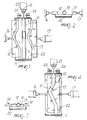
- stage (a) the tubular component 10 is closed at the front, at the end 11, so as to prevent the escape of the gas, generally air, that is injected inside the tubular component to keep its walls mutually apart.
- the tubular component is in fact still in the plastic state and any contact between the walls would lead to immediate mutual adhesion.
- the tubular component 10 is cut and sealed by the sealing and cutting pincers 24.
- the tubular component 10 is engaged by a shaping unit 12 and 13, which engages the tubular component by moving in the direction indicated by the arrows 14.
- the two parts 12 and 13 of the shaping unit can each be moved by at least one actuator cylinder 16 and 17.
- stage (b) the tubular component 10, supported by the shaping unit 12 and 13 (which can also be heated) is still at high temperature and in the plastic state, and is deposited on a high-level half-mold part 15.
- the half-mold can be composed of various parts, which are identified according to their distance (elevation) from the ground for the purposes of the present invention.
- the high-level half-mold part 15, in particular, is at a higher level than a low-level half-mold part 18 located at a lower level.
- Stage (b) is described with particular reference to Figures 5, 6, and 7.
- stage (c) the tubular component 10, still in the plastic state, now free from engagement with the shaping unit 12 and 13, rested on the raised half-mold part 15, has a protruding part 19, shown in dashed lines, that descends freely by gravity onto the lower half-mold part 18, in the direction of the arrow 9, until it reaches the position shown in dot-and-dash lines.
- Stage (c) is described with particular reference to Figure 7.
- stage (d) With particular reference to Figure 8, the upper part of the mold 20 is closed and the tubular component is blow-molded, by inserting a needle, until the cavity of the mold is completely filled.
- the shaping unit 12 and 13 acts mainly in two dimensions, on a substantially horizontal plane.
- the free descent of a part 19 of the tubular component 10 occurs in a third, substantially vertical dimension.
- the device according to the invention includes: a shaping unit 12 and 13 to shape the tubular component prior to deposition on a half-mold; a nozzle 21 for introducing gas inside the tubular component 10 during an extrusion; and a conveyor device 22 for conveying the tubular component 10 during extrusion and allowing engagement of the shaping unit 12 and 13.
- the shaping unit 12, 13 is actuated by parts that can move in substantially horizontal direction 12 and 13.
- the shaping unit 12 and 13 is formed by two complementary bodies 12 and 13 that engage the opposite sides of the tubular component 10.
- the conveyor device 22 acts substantially in a horizontal direction, and according to the embodiment shown in Figures 1 to 4, it is formed by a conveyor belt that preferably works on a horizontal plane.
- the half-mold 15, 18 is preferably arranged below the extrusion region, so that there is no need to move the tubular component 10 horizontally.
- the extrusion head 23 is arranged horizontally, so as to be able to perform a horizontal extrusion, so that the tubular component 10 is immediately in the position that is suitable for depositing it on the half-mold.
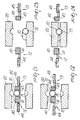
- the shaping unit 12, 13 includes two parts 40, 41, 42, 43 that allow a relative movement of one with respect to the other.
- a lateral part 40, 42 laterally supports the tubular component 10 and is in turn supported by an actuator device 16, 17.
- a lower part 41, 43 supports, in a downward region, the tubular component 10.
- the lower part 41, 43 can be moved with respect to the lateral part 40, 42 by virtue of the auxiliary actuator device 40, 42, which is formed for example by a pair of pneumatic cylinders 44, 45.
- This embodiment is preferred because it reduces the possibility of adhesion between the tubular component and the shaping unit 12, 13, thus offering the best operating reliability.
- Figures 21-24 furthermore illustrate, in succession, the development of the relative motion of the lateral part and of the lower part, so as to allow an adequate positioning of the tubular component in the lower half-mold 15, 18.
- the conveyor device 25 is formed by a pulling clamp that is arranged outside the tubular component 10.
- the shaping unit 12, 13 can even be closed before the engagement of the conveyor device 25, as shown in the figures.
- the tubular component it is preferable to first extrude the tubular component completely, without shaping it during extrusion, and then, once extrusion has ended, shape it and finally transfer it into the mold.
- the conveyor device is formed by a pusher rod that is arranged inside the tubular component.
- the pusher rod is arranged inside the extrusion head 23 and can push the tubular component forward as it is being extruded.
- the tubular component can be extruded only when straight and the shaping unit 12 and 13 can engage the tubular component only at the end of the extrusion.
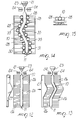
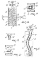
- the shaping unit is formed by multiple movable parallel bodies 26, whose profile can be altered by engagement with a template 27.
- This embodiment has the advantage of allowing prompt and low-cost variation of the profile, simply by changing the template 27.
- the shaping unit is formed by multiple motorized rollers 28 and 29 that have vertical axes.
- the shaping unit is formed by two complementary parts 30 and 31, 32 and 33, that are separated when the shaped tubular component is exactly above the mold, thus depositing it on the half-mold part 15, as shown in particular by Figure 17.
- the shaping unit is formed by multiple motorized rollers 34 that have a horizontal axis.
- the tubular component 10 shaped above the rollers 34 is picked up by multiple clamps 35 that can carry it and deposit it on the half-mold part 15.
- the actuator device 16, 17 can be formed by ballscrews, by toggle systems, or by toothed belts, instead of by the piston-and-cylinder units shown in the figures.
- toothed belts are particularly preferred due to their higher speed, lack of noise, and controllability.
Landscapes
- Engineering & Computer Science (AREA)
- Mechanical Engineering (AREA)
- Manufacturing & Machinery (AREA)
- Robotics (AREA)
- Blow-Moulding Or Thermoforming Of Plastics Or The Like (AREA)
- Moulds For Moulding Plastics Or The Like (AREA)
- Extrusion Moulding Of Plastics Or The Like (AREA)
- Processing And Handling Of Plastics And Other Materials For Molding In General (AREA)
- Supplying Of Containers To The Packaging Station (AREA)
- Making Paper Articles (AREA)
Claims (22)
- Procédé pour fabriquer un corps tubulaire moulé par soufflage, possédant des dimensions multiples, qui comprend les étapes suivantes :a) une extrusion complète d'un composant tubulaire (10), qui est fermé au niveau de sa partie avant (11), avec injection d'un gaz à l'intérieur dudit composant tubulaire, b) ensuite, une fois achevée ladite extrusion, engagement d'une unité de mise en forme (12,13) avec ledit composant tubulaire, ledit engagement mettant en forme ledit élément tubulaire,c) dépôt dudit composant tubulaire mis en forme (10), à l'état plastique, sur une partie formant moitié de moule (15),d) fermeture de ladite moitié de moule et moulage par soufflage.
- Procédé selon la revendication 1, selon lequel ladite unité de mise en forme agit principalement dans deux dimensions, dans un plan essentiellement horizontal, ledit procédé comprenant une descente libre de ladite partie dudit composant tubulaire (10) suivant une troisième dimension essentiellement verticale (9).
- Procédé selon au moins l'une des revendications précédentes, selon lequel, pendant ladite extrusion, ledit composant tubulaire (10) est en contact avec un dispositif convoyeur (22) qui fonctionne de préférence dans une direction horizontale.
- Procédé selon la revendication 3, dans lequel ledit dispositif convoyeur est formé par une bande convoyeuse (22) qui agit de préférence dans un plan horizontal.
- Procédé selon au moins l'une des revendications précédentes, dans lequel ledit dispositif convoyeur est formé par une pince de tirage (25) qui est disposée à l'extérieur dudit composant tubulaire.
- Procédé selon au moins l'une des revendications précédentes, selon lequel ledit dispositif convoyeur est formé par une tige formant poussoir qui est disposée à l'intérieur dudit composant tubulaire.
- Procédé selon au moins l'une des revendications précédentes, selon lequel ladite unité de mise en forme est formée par deux corps complémentaires (11,12,13) qui s'appliquent contre les côtés opposés dudit composant tubulaire (10).
- Procédé selon au moins l'une des revendications précédentes, selon lequel ladite unité de- mise en forme est formée par de multiples corps parallèles mobiles (26), dont le profil peut être modifié moyennant l'utilisation d'un gabarit (27).
- Procédé selon au moins l'une des revendications précédentes, selon lequel une tête d'extrusion (23) est disposée horizontalement de manière à exécuter une extrusion horizontale.
- Procédé selon au moins l'une des revendications précédentes, selon lequel ladite moitié de moule (15,1R) est disposée essentiellement au-dessous d'une zone d'extrusion.
- Dispositif pour fabriquer un corps moulé tubulaire possédant des dimensions multiples, comprenant : une unité de mise en forme (12,13) pour donner sa forme audit composant tubulaire (10) avant son dépôt dans une moitié de moule (15,18); une buse (21) pour injecter du gaz à l'intérieur dudit composant tubulaire (12) pendant une extrusion; un dispositif convoyeur (22) pour convoyer ledit composant tubulaire pendant ladite extrusion et permettre une application de ladite unité de mise en forme (12,13); ladite unité de mise en forme comprenant deux parties (40,41,42,43), qui peuvent avoir un déplacement relatif l'une par rapport à l'autre, ledit déplacement relatif réalisant la mise en forme dudit composant tubulaire; ledit dispositif convoyeur étant distinct et pourvu d'un mouvement indépendant de ladite unité de mise en forme.
- Dispositif selon la revendication 11, dans lequel ladite unité de mise en forme (12,13) est actionnée par des dispositifs qui peuvent se déplacer dans une direction essentiellement horizontale.
- Dispositif selon au moins l'une des revendications précédentes, dans lequel ledit dispositif convoyeur (22) agit essentiellement dans une direction horizontale.
- Dispositif selon au moins l'une des revendications précédentes, dans lequel ledit dispositif convoyeur (22) est formé par une bande convoyeuse qui fonctionne de préférence dans un plan horizontal.
- Dispositif selon au moins l'une des revendications précédentes, dans lequel ledit dispositif convoyeur est formé par une pince de tirage (25) qui est disposée à l'extérieur dudit composant tubulaire.
- Dispositif selon au moins l'une des revendications précédentes, dans lequel ledit dispositif convoyeur est formé par une tige formant poussoir qui est disposée à l'intérieur dudit composant tubulaire.
- Dispositif selon au moins l'une des revendications précédentes, dans lequel ladite unité de mise en forme (12,13) est formée de deux corps complémentaires (12,13) qui s'appliquent contre les côtés opposés dudit composant tubulaire (10).
- Dispositif selon au moins l'une des revendications précédentes, dans lequel ladite unité de mise en forme est formée par de multiples corps parallèles mobiles (26), dont le profil peut être modifié par application contre un gabarit (27).
- Dispositif selon au moins l'une des revendications précédentes, dans lequel une tête d'extrusion (23) est disposée horizontalement de manière à exécuter une extrusion horizontale.
- Dispositif selon au moins l'une des revendications précédentes, dans lequel ladite moitié de moule (15,18) est disposée au-dessous d'une zone d'extrusion.
- Dispositif selon au moins l'une des revendications précédentes, dans lequel lesdites deux parties comprennent une partie latérale (40,42) et une partie inférieure (41,43).
- Dispositif selon au moins l'une des revendications précédentes, dans lequel une direction de déplacement de ladite unité de mise en forme est sensiblement perpendiculaire à une direction de convoyage dudit dispositif convoyeur.
Applications Claiming Priority (3)
| Application Number | Priority Date | Filing Date | Title |
|---|---|---|---|
| IT95MI000479A IT1275894B1 (it) | 1995-03-13 | 1995-03-13 | Procedimento per produrre un corpo tubolare soffiato pluridimensionale e dispositivo per realizzare il procedimento |
| ITMI950479 | 1995-03-13 | ||
| PCT/EP1996/000936 WO1996028295A1 (fr) | 1995-03-13 | 1996-03-06 | Procede de production d'un corps moule par soufflage presentant des dimensions multiples et dispositif permettant d'appliquer ledit procede |
Publications (2)
| Publication Number | Publication Date |
|---|---|
| EP0814948A1 EP0814948A1 (fr) | 1998-01-07 |
| EP0814948B1 true EP0814948B1 (fr) | 2000-07-05 |
Family
ID=11370862
Family Applications (1)
| Application Number | Title | Priority Date | Filing Date |
|---|---|---|---|
| EP96907361A Expired - Lifetime EP0814948B1 (fr) | 1995-03-13 | 1996-03-06 | Procede de production d'un corps moule par soufflage presentant des dimensions multiples et dispositif permettant d'appliquer ledit procede |
Country Status (15)
| Country | Link |
|---|---|
| US (1) | US5965082A (fr) |
| EP (1) | EP0814948B1 (fr) |
| JP (1) | JPH11501876A (fr) |
| KR (1) | KR19980702612A (fr) |
| AT (1) | ATE194308T1 (fr) |
| AU (1) | AU5102396A (fr) |
| BR (1) | BR9607355A (fr) |
| CA (1) | CA2213012A1 (fr) |
| CZ (1) | CZ288297A3 (fr) |
| DE (1) | DE69609169T2 (fr) |
| ES (1) | ES2147372T3 (fr) |
| IT (1) | IT1275894B1 (fr) |
| PL (1) | PL322070A1 (fr) |
| TR (1) | TR199700952T1 (fr) |
| WO (1) | WO1996028295A1 (fr) |
Cited By (1)
| Publication number | Priority date | Publication date | Assignee | Title |
|---|---|---|---|---|
| TWI423870B (zh) * | 2009-08-31 | 2014-01-21 | Sumitomo Bakelite Co | 成形體之製造裝置、成形體之製造方法及成形體 |
Families Citing this family (14)
| Publication number | Priority date | Publication date | Assignee | Title |
|---|---|---|---|---|
| DE19727366A1 (de) * | 1997-06-27 | 1999-01-07 | Kautex Maschinenbau Gmbh | Verfahren und Vorrichtung zum Herstellen von gekrümmten Hohlkörpern aus thermoplastischem Kunststoff |
| FR2773098B1 (fr) * | 1997-12-30 | 2000-03-17 | Solvay | Dispositif et procede de preformage d'une paraison extrudee |
| US6838041B2 (en) * | 1998-03-11 | 2005-01-04 | William W. Rowley | Post formation profile processing |
| US6176699B1 (en) * | 1999-04-28 | 2001-01-23 | Walbro Corporation | Parison handling device |
| DE19922490C2 (de) * | 1999-05-15 | 2001-06-28 | Fischer W Mueller Blasformtech | Verfahren und Vorrichtung zum Herstellen von hohlkörperförmigen Artikeln aus thermoplastischem Kunststoff durch Saugblasen |
| US6730622B2 (en) * | 1999-12-21 | 2004-05-04 | The Procter & Gamble Company | Electrical cable |
| BE1013334A3 (fr) * | 2000-02-29 | 2001-12-04 | Solvay | Procede et dispositif d'extrusion-moulage de corps creux en matiere thermoplastique. |
| KR100789014B1 (ko) * | 2000-10-19 | 2007-12-26 | 코스마 인터내셔널 인크. | 관형 부품을 하이드로포밍하기 위한 장치 및 방법 |
| DE10258996A1 (de) * | 2002-12-16 | 2004-07-01 | Scholz, Rüdiger | Verfahren zur Herstellung von Hohlprofilen und Vorrichtung zur Durchführung dieses Verfahrens |
| DE10308447A1 (de) * | 2003-02-24 | 2004-09-09 | Etimex Technical Components Gmbh | Verfahren und Vorrichtung zum Herstellen nahtloser Formkörper |
| FR2868727B1 (fr) * | 2004-04-08 | 2007-10-05 | Inergy Automotive Systems Res | Procede et dispositif d'extrusion-moulage de corps creux en matiere thermoplastique |
| FR2870159A1 (fr) * | 2004-05-14 | 2005-11-18 | Itt Mfg Enterprises Inc | Procede de realisation en continu d'un composant comportant un corps tubulaire cintre |
| JP7032949B2 (ja) * | 2018-02-14 | 2022-03-09 | 三桜工業株式会社 | 曲げ成形型 |
| US12434426B2 (en) * | 2023-12-11 | 2025-10-07 | Carbofix Spine Inc | Device for maintaining the shape of cross-sectional profile of an elongated element including composite material, and a device for bending thereof |
Family Cites Families (19)
| Publication number | Priority date | Publication date | Assignee | Title |
|---|---|---|---|---|
| US3864445A (en) * | 1972-01-26 | 1975-02-04 | Phillips Petroleum Co | Grasping parison preform at right angle to mold parting line |
| JPS5310659A (en) * | 1976-07-16 | 1978-01-31 | Nozaki Seisakushiyo Kk | Method of producing bent pipe |
| US4301111A (en) * | 1980-03-20 | 1981-11-17 | W. R. Grace & Co., Cryovac Division | Horizontal blow molding |
| DE3038590C2 (de) * | 1980-10-13 | 1986-11-20 | Battenfeld Maschinenfabriken Gmbh, 5882 Meinerzhagen | Verfahren und Vorrichtung zum Extrudieren eines schlauchförmigen Vorformlings in einer Blasform, deren Formhohlraum eine vom gradlinigen Verlauf abweichende Längsachse aufweist |
| DE3314682A1 (de) * | 1983-04-22 | 1984-10-25 | Gebr. Happich Gmbh, 5600 Wuppertal | Profilleiste, insbesondere fuer fahrzeuge, sowie verfahren zum herstellen derselben und vorrichtung zum durchfuehren des verfahrens |
| JPS6141522A (ja) * | 1984-08-06 | 1986-02-27 | Taigaasu Polymer Kk | 折曲した合成樹脂パイプの製造方法 |
| IT1183969B (it) * | 1985-11-22 | 1987-10-22 | Plast Di Crupi D E C Snc C | Apparecchiatura e procedimento per fabbricare articoli sagomati di materiale plastico particolarmente tubi di riempimento per serbatoi del carburante per autoveicoli |
| DE3618446C1 (de) * | 1986-05-31 | 1988-02-11 | Etimex Kunststoff | Verfahren und Vorrichtung zum Blasformen von gekruemmten Hohlkoerpern aus Kunststoff |
| NO864535L (no) * | 1986-11-13 | 1988-05-16 | Dyno Kongsvinger | Fremgangsmaate for blaase- eller vakuumfremstilling av en termoplastisk slange som krummer i minst ett plan. |
| CA1273762C (fr) * | 1987-06-18 | 1990-09-11 | Methode et dispositif de moulage par soufflage | |
| JPH02251414A (ja) * | 1989-03-24 | 1990-10-09 | Ishikawajima Harima Heavy Ind Co Ltd | ブロー成形装置 |
| JPH03193326A (ja) * | 1989-12-22 | 1991-08-23 | Mazda Motor Corp | 樹脂成形品のブロー成形装置 |
| JP2879459B2 (ja) * | 1990-03-12 | 1999-04-05 | 株式会社プラコー | ブロー成形用パリソンを分割金型における受型の成形窪みに供給する方法及びその装置 |
| US5264178A (en) * | 1990-09-27 | 1993-11-23 | Tigers Polymer Corporation | Blow molding method for manufacturing a hollow synthetic resin product using a parison guide |
| DE4305735C1 (de) * | 1993-02-25 | 1994-05-26 | Geiger Technik Gmbh | Blasmaschine |
| JP2826272B2 (ja) * | 1993-10-26 | 1998-11-18 | タイガースポリマー株式会社 | 中空樹脂成形品の製造装置及び製造方法 |
| US5662842A (en) * | 1994-07-18 | 1997-09-02 | Salflex Polymers Ltd. | Process for blow molding hollow objects with independent movement of mold halves |
| GB2293789B (en) * | 1994-10-03 | 1998-08-05 | Draftex Ind Ltd | Moulding apparatus |
| DE4442252C1 (de) * | 1994-11-28 | 1996-06-13 | Geiger Plastic Verwaltung | Vorrichtung zum Transportieren eines Vorformlings von dem Schlauchkopf zu der Blasform einer Blasmaschine |
-
1995
- 1995-03-13 IT IT95MI000479A patent/IT1275894B1/it active IP Right Grant
-
1996
- 1996-03-06 EP EP96907361A patent/EP0814948B1/fr not_active Expired - Lifetime
- 1996-03-06 CZ CZ972882A patent/CZ288297A3/cs unknown
- 1996-03-06 DE DE69609169T patent/DE69609169T2/de not_active Expired - Fee Related
- 1996-03-06 BR BR9607355A patent/BR9607355A/pt active Search and Examination
- 1996-03-06 JP JP8527238A patent/JPH11501876A/ja active Pending
- 1996-03-06 ES ES96907361T patent/ES2147372T3/es not_active Expired - Lifetime
- 1996-03-06 KR KR1019970706017A patent/KR19980702612A/ko not_active Withdrawn
- 1996-03-06 TR TR97/00952T patent/TR199700952T1/xx unknown
- 1996-03-06 PL PL96322070A patent/PL322070A1/xx unknown
- 1996-03-06 AT AT96907361T patent/ATE194308T1/de not_active IP Right Cessation
- 1996-03-06 WO PCT/EP1996/000936 patent/WO1996028295A1/fr not_active Ceased
- 1996-03-06 US US08/894,761 patent/US5965082A/en not_active Expired - Fee Related
- 1996-03-06 AU AU51023/96A patent/AU5102396A/en not_active Abandoned
- 1996-03-06 CA CA002213012A patent/CA2213012A1/fr not_active Abandoned
Cited By (1)
| Publication number | Priority date | Publication date | Assignee | Title |
|---|---|---|---|---|
| TWI423870B (zh) * | 2009-08-31 | 2014-01-21 | Sumitomo Bakelite Co | 成形體之製造裝置、成形體之製造方法及成形體 |
Also Published As
| Publication number | Publication date |
|---|---|
| ATE194308T1 (de) | 2000-07-15 |
| CZ288297A3 (en) | 1997-12-17 |
| BR9607355A (pt) | 1997-12-30 |
| EP0814948A1 (fr) | 1998-01-07 |
| CA2213012A1 (fr) | 1996-09-19 |
| MX9707036A (es) | 1997-11-29 |
| ES2147372T3 (es) | 2000-09-01 |
| WO1996028295A1 (fr) | 1996-09-19 |
| AU5102396A (en) | 1996-10-02 |
| TR199700952T1 (xx) | 1998-02-21 |
| DE69609169D1 (de) | 2000-08-10 |
| ITMI950479A1 (it) | 1996-09-13 |
| KR19980702612A (ko) | 1998-08-05 |
| DE69609169T2 (de) | 2001-03-22 |
| ITMI950479A0 (it) | 1995-03-13 |
| PL322070A1 (en) | 1998-01-05 |
| US5965082A (en) | 1999-10-12 |
| IT1275894B1 (it) | 1997-10-24 |
| JPH11501876A (ja) | 1999-02-16 |
Similar Documents
| Publication | Publication Date | Title |
|---|---|---|
| EP0814948B1 (fr) | Procede de production d'un corps moule par soufflage presentant des dimensions multiples et dispositif permettant d'appliquer ledit procede | |
| CN103025504B (zh) | 用于生产塑料容器的设备 | |
| EP3418027B1 (fr) | Dispositif et procédé de moulage par soufflage | |
| US11478974B2 (en) | Blow molding machine and method for controlling blow molding machine | |
| EP0705678A1 (fr) | Dispositif et procédé de moulage par soufflage d'objets tridimensionnels | |
| CN1043515C (zh) | 注射拉伸吹制成形的方法和装置 | |
| US8506875B2 (en) | Single sided shuttle-type blow molding method | |
| US6358038B1 (en) | Injection stretch blow molding machine | |
| JP3477169B2 (ja) | 熱可塑性材料からなるブランクのブロー成形容器の製造方法とそのプラント | |
| US3390427A (en) | Injection blow molding machines | |
| EP1231044B2 (fr) | Procédé et appareil de moulage par soufflage avec chariots de transport de moules | |
| CN110539471A (zh) | 一种遮阳板片材机吹塑成型方法 | |
| US6649120B1 (en) | Blow molding apparatus and method | |
| US6416313B1 (en) | Blow molding machine for low-waste blow molding | |
| MXPA97007036A (en) | Method for producing a blowed molded body that has multiple dimensions and a device to carry out the met | |
| EP3663070A1 (fr) | Nouveau procédé de moulage par soufflage | |
| CN1178499A (zh) | 生产多维吹塑体的方法和实现该方法的装置 | |
| JPH11314223A (ja) | 押出しパリソンを予備成形する装置及び方法 | |
| CN201552742U (zh) | 集注胚和吹瓶于一体的塑料制瓶机 | |
| US4095967A (en) | Method of manufacturing glass fittings with side channel | |
| JPH0430901B2 (fr) |
Legal Events
| Date | Code | Title | Description |
|---|---|---|---|
| PUAI | Public reference made under article 153(3) epc to a published international application that has entered the european phase |
Free format text: ORIGINAL CODE: 0009012 |
|
| 17P | Request for examination filed |
Effective date: 19970922 |
|
| AK | Designated contracting states |
Kind code of ref document: A1 Designated state(s): AT BE DE ES FR GB IE IT NL PT SE |
|
| AX | Request for extension of the european patent |
Free format text: SI PAYMENT 970922 |
|
| 17Q | First examination report despatched |
Effective date: 19990427 |
|
| GRAG | Despatch of communication of intention to grant |
Free format text: ORIGINAL CODE: EPIDOS AGRA |
|
| GRAG | Despatch of communication of intention to grant |
Free format text: ORIGINAL CODE: EPIDOS AGRA |
|
| GRAH | Despatch of communication of intention to grant a patent |
Free format text: ORIGINAL CODE: EPIDOS IGRA |
|
| GRAH | Despatch of communication of intention to grant a patent |
Free format text: ORIGINAL CODE: EPIDOS IGRA |
|
| GRAA | (expected) grant |
Free format text: ORIGINAL CODE: 0009210 |
|
| AK | Designated contracting states |
Kind code of ref document: B1 Designated state(s): AT BE DE ES FR GB IE IT NL PT SE |
|
| AX | Request for extension of the european patent |
Free format text: SI PAYMENT 19970922 |
|
| PG25 | Lapsed in a contracting state [announced via postgrant information from national office to epo] |
Ref country code: NL Free format text: LAPSE BECAUSE OF FAILURE TO SUBMIT A TRANSLATION OF THE DESCRIPTION OR TO PAY THE FEE WITHIN THE PRESCRIBED TIME-LIMIT Effective date: 20000705 Ref country code: BE Free format text: LAPSE BECAUSE OF FAILURE TO SUBMIT A TRANSLATION OF THE DESCRIPTION OR TO PAY THE FEE WITHIN THE PRESCRIBED TIME-LIMIT Effective date: 20000705 |
|
| REF | Corresponds to: |
Ref document number: 194308 Country of ref document: AT Date of ref document: 20000715 Kind code of ref document: T |
|
| REG | Reference to a national code |
Ref country code: IE Ref legal event code: FG4D |
|
| REF | Corresponds to: |
Ref document number: 69609169 Country of ref document: DE Date of ref document: 20000810 |
|
| REG | Reference to a national code |
Ref country code: ES Ref legal event code: FG2A Ref document number: 2147372 Country of ref document: ES Kind code of ref document: T3 |
|
| ITF | It: translation for a ep patent filed | ||
| PG25 | Lapsed in a contracting state [announced via postgrant information from national office to epo] |
Ref country code: SE Free format text: LAPSE BECAUSE OF FAILURE TO SUBMIT A TRANSLATION OF THE DESCRIPTION OR TO PAY THE FEE WITHIN THE PRESCRIBED TIME-LIMIT Effective date: 20001005 |
|
| PG25 | Lapsed in a contracting state [announced via postgrant information from national office to epo] |
Ref country code: PT Free format text: LAPSE BECAUSE OF FAILURE TO SUBMIT A TRANSLATION OF THE DESCRIPTION OR TO PAY THE FEE WITHIN THE PRESCRIBED TIME-LIMIT Effective date: 20001006 |
|
| ET | Fr: translation filed | ||
| NLV1 | Nl: lapsed or annulled due to failure to fulfill the requirements of art. 29p and 29m of the patents act | ||
| PG25 | Lapsed in a contracting state [announced via postgrant information from national office to epo] |
Ref country code: IE Free format text: LAPSE BECAUSE OF NON-PAYMENT OF DUE FEES Effective date: 20010306 |
|
| PLBE | No opposition filed within time limit |
Free format text: ORIGINAL CODE: 0009261 |
|
| STAA | Information on the status of an ep patent application or granted ep patent |
Free format text: STATUS: NO OPPOSITION FILED WITHIN TIME LIMIT |
|
| 26N | No opposition filed | ||
| REG | Reference to a national code |
Ref country code: GB Ref legal event code: IF02 |
|
| REG | Reference to a national code |
Ref country code: IE Ref legal event code: MM4A |
|
| PGFP | Annual fee paid to national office [announced via postgrant information from national office to epo] |
Ref country code: GB Payment date: 20030328 Year of fee payment: 8 |
|
| PGFP | Annual fee paid to national office [announced via postgrant information from national office to epo] |
Ref country code: ES Payment date: 20030331 Year of fee payment: 8 |
|
| PG25 | Lapsed in a contracting state [announced via postgrant information from national office to epo] |
Ref country code: GB Free format text: LAPSE BECAUSE OF NON-PAYMENT OF DUE FEES Effective date: 20040306 |
|
| PG25 | Lapsed in a contracting state [announced via postgrant information from national office to epo] |
Ref country code: ES Free format text: LAPSE BECAUSE OF NON-PAYMENT OF DUE FEES Effective date: 20040308 |
|
| GBPC | Gb: european patent ceased through non-payment of renewal fee | ||
| REG | Reference to a national code |
Ref country code: ES Ref legal event code: FD2A Effective date: 20040308 |
|
| PGFP | Annual fee paid to national office [announced via postgrant information from national office to epo] |
Ref country code: AT Payment date: 20080304 Year of fee payment: 13 |
|
| PGFP | Annual fee paid to national office [announced via postgrant information from national office to epo] |
Ref country code: FR Payment date: 20080228 Year of fee payment: 13 Ref country code: DE Payment date: 20080219 Year of fee payment: 13 |
|
| PGFP | Annual fee paid to national office [announced via postgrant information from national office to epo] |
Ref country code: IT Payment date: 20080328 Year of fee payment: 13 |
|
| PG25 | Lapsed in a contracting state [announced via postgrant information from national office to epo] |
Ref country code: AT Free format text: LAPSE BECAUSE OF NON-PAYMENT OF DUE FEES Effective date: 20090306 |
|
| REG | Reference to a national code |
Ref country code: FR Ref legal event code: ST Effective date: 20091130 |
|
| PG25 | Lapsed in a contracting state [announced via postgrant information from national office to epo] |
Ref country code: DE Free format text: LAPSE BECAUSE OF NON-PAYMENT OF DUE FEES Effective date: 20091001 |
|
| PG25 | Lapsed in a contracting state [announced via postgrant information from national office to epo] |
Ref country code: FR Free format text: LAPSE BECAUSE OF NON-PAYMENT OF DUE FEES Effective date: 20091123 |
|
| PG25 | Lapsed in a contracting state [announced via postgrant information from national office to epo] |
Ref country code: IT Free format text: LAPSE BECAUSE OF NON-PAYMENT OF DUE FEES Effective date: 20090306 |