EP0814959B1 - Procede d'actionnement d'une unite, par ex. une plieuse de presse rotative - Google Patents
Procede d'actionnement d'une unite, par ex. une plieuse de presse rotative Download PDFInfo
- Publication number
- EP0814959B1 EP0814959B1 EP96905713A EP96905713A EP0814959B1 EP 0814959 B1 EP0814959 B1 EP 0814959B1 EP 96905713 A EP96905713 A EP 96905713A EP 96905713 A EP96905713 A EP 96905713A EP 0814959 B1 EP0814959 B1 EP 0814959B1
- Authority
- EP
- European Patent Office
- Prior art keywords
- rotation
- sub
- drive
- motor
- assemblies
- Prior art date
- Legal status (The legal status is an assumption and is not a legal conclusion. Google has not performed a legal analysis and makes no representation as to the accuracy of the status listed.)
- Expired - Lifetime
Links
- 238000000034 method Methods 0.000 title claims description 11
- 238000000429 assembly Methods 0.000 claims description 16
- 230000001360 synchronised effect Effects 0.000 claims description 4
- 238000005520 cutting process Methods 0.000 description 12
- 230000000712 assembly Effects 0.000 description 8
- 238000004519 manufacturing process Methods 0.000 description 3
- 238000010586 diagram Methods 0.000 description 2
- 230000005540 biological transmission Effects 0.000 description 1
- 239000002131 composite material Substances 0.000 description 1
- 230000007547 defect Effects 0.000 description 1
- 238000001514 detection method Methods 0.000 description 1
- 238000009826 distribution Methods 0.000 description 1
- 230000000694 effects Effects 0.000 description 1
- 238000013213 extrapolation Methods 0.000 description 1
- 125000000524 functional group Chemical group 0.000 description 1
- 238000012423 maintenance Methods 0.000 description 1
- 239000000463 material Substances 0.000 description 1
- 230000003287 optical effect Effects 0.000 description 1
Images

Classifications
-
- B—PERFORMING OPERATIONS; TRANSPORTING
- B41—PRINTING; LINING MACHINES; TYPEWRITERS; STAMPS
- B41F—PRINTING MACHINES OR PRESSES
- B41F13/00—Common details of rotary presses or machines
- B41F13/004—Electric or hydraulic features of drives
- B41F13/0045—Electric driving devices
-
- B—PERFORMING OPERATIONS; TRANSPORTING
- B65—CONVEYING; PACKING; STORING; HANDLING THIN OR FILAMENTARY MATERIAL
- B65H—HANDLING THIN OR FILAMENTARY MATERIAL, e.g. SHEETS, WEBS, CABLES
- B65H43/00—Use of control, checking, or safety devices, e.g. automatic devices comprising an element for sensing a variable
-
- B—PERFORMING OPERATIONS; TRANSPORTING
- B65—CONVEYING; PACKING; STORING; HANDLING THIN OR FILAMENTARY MATERIAL
- B65H—HANDLING THIN OR FILAMENTARY MATERIAL, e.g. SHEETS, WEBS, CABLES
- B65H45/00—Folding thin material
- B65H45/12—Folding articles or webs with application of pressure to define or form crease lines
- B65H45/28—Folding in combination with cutting
-
- B—PERFORMING OPERATIONS; TRANSPORTING
- B41—PRINTING; LINING MACHINES; TYPEWRITERS; STAMPS
- B41P—INDEXING SCHEME RELATING TO PRINTING, LINING MACHINES, TYPEWRITERS, AND TO STAMPS
- B41P2213/00—Arrangements for actuating or driving printing presses; Auxiliary devices or processes
- B41P2213/70—Driving devices associated with particular installations or situations
- B41P2213/73—Driving devices for multicolour presses
- B41P2213/734—Driving devices for multicolour presses each printing unit being driven by its own electric motor, i.e. electric shaft
Definitions
- the invention relates to a method for driving a Aggregates of a rotary printing press according to the Preamble of claim 1.
- the post-published EP 06 92 377 A2 shows a Method for driving rotating assemblies Printing press, with one drive for each assembly monitors a tolerance range of their rotational angular position becomes.
- EP 05 67 741 A1 discloses a method for Driving rotating components or assemblies, being for each selected electromotive drive selected assemblies a current tolerance range their rotational angular position is specified and the Assemblies with an adjustable speed and angle of rotation Drive are equipped. Doing so will be ongoing Current actual value of the rotational angular positions and on Current setpoint of the rotational angular positions of each selected drive compared with each other.
- DE 43 22 744 A1 describes a device for Driving an aggregate, each being drivable rotating assembly a separate rotation-angle-controlled motor is assigned and wherein a computer unit is provided which Angular position of rotation of selected assemblies or Compares engines.
- the DE-AS 19 60 565 are interchangeable Folders for web-fed rotary printing machines become known whose rotating components, such as Perforating rollers, puncturing, cutting and Folding knife cylinder, longitudinal folding cylinder or folding roller as well as bucket wheel and belt delivery via a longitudinal shaft, a cross shaft and standing waves and Gear drive trains are driven.
- rotating components such as Perforating rollers, puncturing, cutting and Folding knife cylinder, longitudinal folding cylinder or folding roller as well as bucket wheel and belt delivery via a longitudinal shaft, a cross shaft and standing waves and Gear drive trains are driven.
- the invention has for its object a method to drive an aggregate To create rotary printing press.
- An embodiment of the invention is based on a Folder shown in the drawing and is in following described in more detail.
- a folder points in a second or upper level a first former 1 in which a first Paper web 2 receives a first longitudinal fold.
- a First or lower level are two pairs of perforating tabs 3, 4 and 6, 7 each with electric drivable Motors 8, 9 and 11, 12 arranged.
- Each motor 8, 9; 11, 12 is form-fitting with one Perforating roller 3, 4; 6, 7 connected, e.g. B. by Flanging.
- the paper web 2 is subsequently between a knife cylinder 13 provided with a motor 14 and a cutting groove provided with motor 17 and Folding knife cylinder 16 in not shown cut, if necessary, on the cutting grooves and Folding knife cylinder 16 collected and subsequently by means of a motor 19 Folding jaw cylinder 18 cross-folded and one with a motor 22 provided further transverse folding cylinder 21 become.
- the cross folding cylinder 21 either serves for introducing a second cross fold into the Folded product or as a transport cylinder.
- the folded product is subsequently one with a tape control system 23
- Motor 26 provided second longitudinal folding device 24 fed, in which the folded product longitudinally and by means of an underlying motor 28 Paddle wheel 27 collected and a delivery belt 29th is fed.
- a second former 44 is arranged by means of which is a second paper web 46 and one of the two product routes mentioned longitudinal folder 24 or 38 is fed while the other paper web 2 to one next to that Knife cylinder 13 section cassette to be led.
- the section cassette consists of two Cross-cutting cylinders 47, 48, which with motors 49, 51 are provided, a tape control system 52 and one Paddle wheel 53, also provided with a motor 54 and a delivery belt 56.
- the drivable rotating components B3, B4, B6 to Bn are in side frames 57; 58 stored, of which the side frame 58 only with a small Detail is shown.
- the rotating components B3, B4, B6 to Bn can also be arranged in modules that according to the production requirements are put together. Such a design Folding apparatus is described in DE 36 26 287 C2.
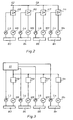
- Each of the or only selected rotating components or assemblies B3, B4, B6 to Bn is positively connected to a position sensor L3, L4, L6 to Ln.
- the position encoder z. B. can be designed as a rotary pulse generator with a reference mark and also on the rotating component motor unit B3, M8; B4, M9; B6, M11 to Bn, Mn can be arranged in a form-fitting manner.
- Each motor M8, M9, M11 to Mn as well as each position encoder L3, L4, L6 to Ln of a rotating assembly B3, B4, B6 to Bn is electrically connected to a drive controller A8, A9, A11 to An with integrated position detection. All drive controllers A8, A9, A11 to An are connected for the purpose of data exchange for synchronization via a common data bus 59 (FIG. 2), the input of which is connected to the electrical devices of the machine control center.
- M8; M9; M11 to Mn of each module B3: B4; B6; to Bn a current tolerance range of the rotation angle position is specified.
- Selected drives M8; M9; M11 to Mn an instantaneous actual value of the rotational angular positions with the instantaneous nominal value of the rotational angular positions of each selected drive M8; M9; M11 to Mn, e.g. B. compared with each other by means of a reference mark. If the instantaneous tolerance range of the rotational angular positions of at least one of the selected drives M8; M9; M11 to Mn will be a safety device to prevent further supply of material to the units, e.g. B.
- a known cutting device 63 activated for the paper strand.
- a safety device can, for. B. counteracting cutting knives, which are the incoming into the folder or printing unit paper webs 2; 46 or strands.
- a synchronous quick stop for selected rotating assemblies B3; B4; B6 to Bn initiated. Synchronous rapid stop means that the selected individual modules B3; B4; B6 to Bn at least until all drives M8 stop; M9; M11 to Mn remain synchronized.
- the current and actual values can advantageously be Setpoints of the rotational angular positions of each selected Assembly B3; B4; B6 to Bn in the tolerance range in the Computer unit 61 continuously stored and also be extrapolated. Should the extrapolation of the Current actual values of the rotational angular positions at least only one of the selected assembly B3; B4; B6 to Bn Be expected to leave the tolerance range an electronic signal from a computer unit 61 generated and delivered to an electrical control unit. From her z. B. an optical and / or acoustic Warning signal or other control commands issued. It can but also a quick stop described above.
- the quick stop guide includes the Safety device z. B.
- each motor is M8, M9, M11 to Mn of a rotating assembly B3, B4, B6 to Bn electrically with a power unit N8, N9, N11 connected to Nn.
- Both the power units N8, N9, N11 to Nn as well as the position sensors L3, L4, L6 to Ln one rotating assembly B3, B4, B6 to Bn are electrical with a computer unit 61, e.g. B. a composite of one or more signal processors to detect the Position, d. H. the rotational angular position of the Rotating parts connected.
- Each power section N8, N9, N11 to Nn can consist of thyristors for DC and for AC consist of IGBTs.
Landscapes
- Engineering & Computer Science (AREA)
- Mechanical Engineering (AREA)
- Folding Of Thin Sheet-Like Materials, Special Discharging Devices, And Others (AREA)
- Rotary Presses (AREA)
- Inking, Control Or Cleaning Of Printing Machines (AREA)
Claims (13)
- Procédé d'actionnement de parties de construction ou de groupes de construction rotatifs (B3 ; B4 ; B6 à Bn), de groupes d'une machine à imprimer rotative, sachant que, pour chaque entraínement à moteur électrique (M8 ; M9 ; M11 à Mn) sélectionné, de groupes de construction (B3 ; B4 ; B6 à Bn) sélectionnés, une plage de tolérance momentanée, concernant sa position angulaire en rotation, est prédéterminée, sachant que les groupes de construction (B3 ; B4 ; B6 à Bn) sélectionnés sont équipés d'un dispositif d'entraínement (M8 ; M9 ; M11 à Mn) à capacité de réglage de la vitesse de rotation et de l'angle de rotation, sachant que, en continu, une valeur réelle momentanée, des positions angulaires en rotation, est comparée à une valeur de consigne momentanée des positions angulaires en rotation de chaque dispositif d'entraínement (M8 ; M9 ; M11 à Mn) sélectionné, sachant que, en cas de dépassement de la plage de tolérance momentanée prédéterminée, de la position angulaire en rotation, d'au moins l'un des dispositifs d'entraínement (M8 ; M9 ; M11 à Mn) sélectionné, un signal est produit et émis par une unité de calcul (61), caractérisé en ce que le signal active un dispositif de sécurité (63), par exemple un dispositif (63) connu en soi, pour le découpage d'un tronçon de bande de papier (2 ; 46) entrant, et en ce qu'un arrêt rapide synchrone, pour les groupes de construction (B3 ; B4 ; B6 à Bn) sélectionnés, est induit.
- Procédé selon la revendication 1, caractérisé en ce que la synchronisation des différents groupes de construction (B3 ; B4 ; B6 à Bn) entre eux, lors du lancement d'un arrêt rapide, est conservée au moins jusqu'à l'arrêt de l'ensemble des dispositifs d'entraínement (M8 ; M9 ; M11 à Mn).
- Procédé selon la revendication 1, caractérisé en ce que la plage de tolérance des positions angulaires en rotation momentanées de chaque groupe de construction (B3 ; B4 ; B6 à Bn) est dimensionnée de manière à ce qu'aucun dégât ne puisse se faire sur la machine.
- Procédé selon la revendication 1, caractérisé en ce que les valeurs réelles et de consigne des positions angulaires en rotation de chaque groupe de construction (B3; B4 ; B6 à Bn), dans la plage de tolérance, sont mémorisées de façon continue et extrapolées, de manière qu'au moins un signal d'avertissement soit émis, avant de quitter la plage de tolérance.
- Dispositif d'entraínement pour la mise en oeuvre du procédé selon les revendications ci-dessus, pour des parties de construction ou des groupes de construction (B3, B4, B6 à Bn) rotatifs, d'une machine à imprimer rotative, à chaque groupe de construction (B3, B4, B6 à Bn), susceptible d'être entraíné, étant associé un moteur à régulation de position angulaire en rotation (M8, M9, M11 à Mn) séparé, en ce qu'une unité de calcul (61), comparant une position angulaire en rotation de groupes de construction (B3, B4, B6 à Bn) ou de moteurs (M8, M9, M11 à Mn) sélectionnés, est prévue, caractérisé en ce qu'un dispositif de sécurité, commandé en fonction de l'écart des positions angulaires en rotation des groupes de construction (B3 ; B4 ; B6 à Bn) ou des moteurs (M8, M9, M11 à Mn) sélectionnés, est prévu.
- Dispositif d'entraínement selon la revendication 4, caractérisé en ce que le moteur (M8, M9, M11 à Mn) respectif est relié, par une liaison par ajustement de forme, à la partie de construction ou au groupe de construction (B3, B4, B6 à Bn) rotatif (rotative), correspondant(e), susceptible d'être entraíné(e).
- Dispositif d'entraínement selon la revendication 5, caractérisé en ce qu'à chaque unité de moteur de partie de construction (B3, M8 ; B4, M9 ; B6, M11 à Bn, Mn) est associé un capteur de position angulaire en rotation (L3, L4, L6 à Ln).
- Dispositif d'entraínement selon la revendication 5, caractérisé en ce qu'à chaque moteur (M8, M9, M11 à Mn) est associé un régulateur d'entraínement (A8, A9, A11 à An).
- Dispositif d'entraínement selon la revendication 8, caractérisé en ce que tous les régulateurs d'entraínement (A8, A9, A11 à An) sont reliés ensemble par un bus de données (59).
- Dispositif d'entraínement selon la revendication 5, caractérisé en ce qu'à chaque moteur (M8, M9, M11 à Mn) est associée une partie de puissance (N8, N9, N11 à Nn).
- Dispositif d'entraínement selon les revendications 7 et 10, caractérisé en ce que chaque capteur de position angulaire en rotation (L3, L4, L6 à Ln) et chaque partie de puissance (N8, N9, N11 à Nn) est relié(e) à une unité de calcul (61).
- Dispositif d'entraínement selon la revendication 5, caractérisé en ce que le dispositif de sécurité contient un dispositif (63) pour le découpage d'un tronçon de papier (2 ; 46).
- Dispositif d'entraínement selon la revendication 5, caractérisé en ce que le dispositif de sécurité est disposé de façon à déclencher un arrêt rapide.
Priority Applications (2)
| Application Number | Priority Date | Filing Date | Title |
|---|---|---|---|
| EP02020031A EP1275499B1 (fr) | 1995-03-18 | 1996-03-12 | Dispositif d'entrainement d'un appareil de pliage d'une machine à imprimer rotative |
| EP05111452A EP1666248B1 (fr) | 1995-03-18 | 1996-03-12 | Dispositif d'entraînement d'un appareil de pliage d'une machine à imprimer rotative |
Applications Claiming Priority (5)
| Application Number | Priority Date | Filing Date | Title |
|---|---|---|---|
| DE19509948 | 1995-03-18 | ||
| DE19509948 | 1995-03-18 | ||
| DE19525169A DE19525169C2 (de) | 1995-03-18 | 1995-07-11 | Verfahren zum Antreiben eines Falzapparates |
| DE19525169 | 1995-07-11 | ||
| PCT/DE1996/000437 WO1996029204A1 (fr) | 1995-03-18 | 1996-03-12 | Procede d'actionnement d'une unite, par ex. une plieuse de presse rotative |
Related Child Applications (2)
| Application Number | Title | Priority Date | Filing Date |
|---|---|---|---|
| EP05111452A Division EP1666248B1 (fr) | 1995-03-18 | 1996-03-12 | Dispositif d'entraînement d'un appareil de pliage d'une machine à imprimer rotative |
| EP02020031A Division EP1275499B1 (fr) | 1995-03-18 | 1996-03-12 | Dispositif d'entrainement d'un appareil de pliage d'une machine à imprimer rotative |
Publications (2)
| Publication Number | Publication Date |
|---|---|
| EP0814959A1 EP0814959A1 (fr) | 1998-01-07 |
| EP0814959B1 true EP0814959B1 (fr) | 2004-05-26 |
Family
ID=26013507
Family Applications (1)
| Application Number | Title | Priority Date | Filing Date |
|---|---|---|---|
| EP96905713A Expired - Lifetime EP0814959B1 (fr) | 1995-03-18 | 1996-03-12 | Procede d'actionnement d'une unite, par ex. une plieuse de presse rotative |
Country Status (5)
| Country | Link |
|---|---|
| US (1) | US5901647A (fr) |
| EP (1) | EP0814959B1 (fr) |
| JP (1) | JP2965705B2 (fr) |
| DE (2) | DE59611338D1 (fr) |
| WO (1) | WO1996029204A1 (fr) |
Families Citing this family (30)
| Publication number | Priority date | Publication date | Assignee | Title |
|---|---|---|---|---|
| DE19516443A1 (de) † | 1995-05-04 | 1996-11-07 | Wifag Maschf | Einzeln angetriebener Falzapparat für eine Rotationsdruckmaschine |
| JP3976401B2 (ja) * | 1998-05-29 | 2007-09-19 | 株式会社山田ドビー | 連続素材送り装置の制御装置 |
| DE19917118B4 (de) | 1999-04-15 | 2004-06-24 | Man Roland Druckmaschinen Ag | Schaufelradausleger |
| US6550385B1 (en) * | 1999-07-12 | 2003-04-22 | Heidelberger Druckmaschine Ag | Cam-independent drive for folding components |
| DE19936291B4 (de) * | 1999-08-02 | 2015-12-24 | Wifag Maschinenfabrik Ag | Bestimmung von Schnittlagen von Bahnsträngen in einer Rotationsdruckmaschine |
| US6279890B1 (en) * | 2000-04-11 | 2001-08-28 | Goss Graphic Systems, Inc. | Combination rotary and jaw folder for a printing press |
| US6902519B2 (en) * | 2000-05-17 | 2005-06-07 | Koenig & Bauer Aktiengesellschaft | Folding device |
| DE10027441A1 (de) | 2000-06-02 | 2001-12-06 | Roland Man Druckmasch | Verfahren und Vorrichtung zur Verhinderung von Maschinenschäden |
| DE10027442B4 (de) | 2000-06-02 | 2005-12-01 | Man Roland Druckmaschinen Ag | Verfahren und Vorrichtung zur Detektion von Bahnrissen |
| JP3431894B2 (ja) * | 2000-09-22 | 2003-07-28 | 株式会社東京機械製作所 | 印刷画像情報に基づいて制御対象を選択する輪転機の同期制御装置 |
| US6752751B2 (en) | 2001-02-23 | 2004-06-22 | Heidelberger Druckmaschinen Ag | Folder with multiple-motor drive |
| DE10116346B4 (de) * | 2001-04-02 | 2006-03-02 | Koenig & Bauer Ag | Falzapparat |
| DE10124977A1 (de) * | 2001-05-21 | 2002-11-28 | Roland Man Druckmasch | Antrieb für einen Zylinder einer Rotationsdruckmaschine |
| DE10128122A1 (de) * | 2001-06-09 | 2002-12-12 | Roland Man Druckmasch | Antrieb für einen Falzapparat |
| US6823792B2 (en) * | 2001-07-26 | 2004-11-30 | Heidelberger Druckmaschinen Ag | Multi-motor drive and method for driving a printing press |
| DE10204362A1 (de) † | 2002-02-02 | 2003-08-14 | Roland Man Druckmasch | Falzapparat einer Rotationsdruckmaschine |
| DE10206578C1 (de) * | 2002-02-18 | 2003-09-18 | Koenig & Bauer Ag | Falzapparat mit einem Falzzylinder |
| DE10208292B4 (de) | 2002-02-26 | 2004-04-15 | Koenig & Bauer Ag | Falzapparat |
| JP3557196B2 (ja) * | 2002-03-29 | 2004-08-25 | 株式会社東京機械製作所 | 連続紙処理装置の連続紙走行位置修正装置 |
| DE10243454C5 (de) * | 2002-09-19 | 2009-10-08 | Koenig & Bauer Aktiengesellschaft | Antriebsvorrichtung einer Bearbeitungsmaschine |
| DE10255235A1 (de) * | 2002-11-26 | 2004-06-03 | Man Roland Druckmaschinen Ag | Antrieb für einen Zylinder einer Rotationsdruckmaschine |
| GB2401820B (en) * | 2003-05-21 | 2007-01-17 | Watkiss Automation Ltd | Booklet production |
| JP2007516913A (ja) * | 2004-01-31 | 2007-06-28 | ケーニッヒ ウント バウエル アクチエンゲゼルシャフト | 印刷される部分の長さを変化させながら、オフセット印刷により被印刷体ウェブに印刷するための少なくとも1つの印刷ユニットを有する印刷機 |
| ATE484476T1 (de) * | 2004-04-05 | 2010-10-15 | Koenig & Bauer Ag | Verfahren und vorrichtungen zum kappen und/oder zuführen eines stranges in eine weiterverarbeitungsstufe |
| TWI252809B (en) * | 2004-05-05 | 2006-04-11 | Bobst Sa | Method and device for initial adjustment of the register of the engraved cylinders of a rotary multicolour press |
| CH697884B1 (de) * | 2004-07-13 | 2009-03-13 | Manroland Ag | Rollenrotationsdruckeinheit. |
| DE102005048472A1 (de) * | 2005-10-07 | 2007-04-12 | Bosch Rexroth Ag | Rotationsdruckmaschine und Verfahren des Betriebs einer Rotationsdruckmaschine |
| DE102006010602A1 (de) * | 2006-03-06 | 2007-09-20 | Maschinenfabrik Wifag | Falzvorrichtung mit auf unterschiedlichen Höhen angeordneten Falzapparaten |
| US20080028902A1 (en) * | 2006-08-03 | 2008-02-07 | Kimberly-Clark Worldwide, Inc. | Dual roll, variable sheet-length, perforation system |
| DE102010028350B4 (de) * | 2010-04-29 | 2014-05-22 | Koenig & Bauer Aktiengesellschaft | Verfahren zur Regelung einer Drehwinkellage und gegebenenfalls einer Rotationsgeschwindigkeit zumindest eines lagegeregelten Antriebsmotors zumindest einer Vorrichtung eines Falzapparats |
Family Cites Families (25)
| Publication number | Priority date | Publication date | Assignee | Title |
|---|---|---|---|---|
| DE1230811B (de) * | 1963-05-17 | 1966-12-22 | Maschf Augsburg Nuernberg Ag | Vorrichtung zum Verhueten von Stoppern im Falzapparat von Druckmaschinen |
| DE1960565B2 (de) * | 1969-12-03 | 1974-11-21 | Koenig & Bauer Ag, 8700 Wuerzburg | Austauschbares Falzwerk für Rollenrotationsdruckmaschinen |
| US3812351A (en) * | 1972-05-25 | 1974-05-21 | Hurletron Inc | Rotary position detector machine control system |
| US3963902A (en) * | 1975-04-29 | 1976-06-15 | Westvaco Corporation | Method and apparatus for pre-registration of a multiple cylinder rotary printing press |
| DD123663A1 (fr) * | 1975-05-12 | 1977-01-12 | ||
| DE7606107U1 (de) * | 1976-02-07 | 1977-08-04 | Stahl Gmbh & Co Maschinenfabrik, 7140 Ludwigsburg | Bogenfalzautomat |
| WO1980000231A1 (fr) * | 1978-07-17 | 1980-02-21 | Deritend Eng Co | Machines pour le traitement d'un materiau en feuille |
| DE3342662A1 (de) * | 1983-11-25 | 1985-06-05 | M.A.N.- Roland Druckmaschinen AG, 6050 Offenbach | Vorrichtung an einer druckmaschine, bestehend aus einem platten- und/oder gummizylinder |
| DD223267A1 (de) * | 1984-03-06 | 1985-06-05 | Textilmaschinenbau Veb | Verfahren zur regelung von n parallel geschalteten antrieben |
| DE3614979C3 (de) * | 1986-05-02 | 1999-12-16 | Heidelberger Druckmasch Ag | Sicherheitssystem für eine Druckmaschine |
| US4809188A (en) * | 1986-10-17 | 1989-02-28 | Spartanics, Ltd. | Strip feeding and control system |
| DE3929227A1 (de) * | 1989-09-02 | 1991-03-07 | Koenig & Bauer Ag | Papierbahntrenn- und -halteeinrichtung |
| DE4012396A1 (de) * | 1990-04-19 | 1991-10-31 | Roland Man Druckmasch | Druckmaschinenanlage |
| US5048810A (en) * | 1990-11-19 | 1991-09-17 | Harris Graphics Corporation | Apparatus for adjusting an anglebar or a compensator roller in a folder of a printing press |
| DE4137979B4 (de) * | 1991-11-19 | 2004-05-06 | Heidelberger Druckmaschinen Ag | Antrieb für eine Druckmaschine mit mindestens zwei mechanisch voneinander entkoppelten Druckwerken |
| US5481971A (en) * | 1991-11-19 | 1996-01-09 | Heidelberger Druckmaschinen Ag | Drive for a printing press with a plurality of printing units |
| DE4214394C2 (de) * | 1992-04-30 | 1998-08-20 | Asea Brown Boveri | Antriebsvorrichtung für eine längswellenlose Rotationsdruckmaschine |
| DE4230938C2 (de) * | 1992-09-16 | 1995-10-05 | Heidelberger Druckmasch Ag | Vorrichtung zur In-Line-Perforation durchlaufender Materialbahnen |
| US5570633A (en) * | 1993-06-01 | 1996-11-05 | Comco Machinery, Inc. | Automated printing press with reinsertion registration control |
| DE4322744C2 (de) * | 1993-07-08 | 1998-08-27 | Baumueller Nuernberg Gmbh | Elektrisches Antriebssystem und Positionierverfahren zur synchronen Verstellung mehrerer dreh- und/oder verschwenkbarer Funktionsteile in Geräten und Maschinen, Antriebsanordnung mit einem Winkellagegeber und Druckmaschine |
| GB2281534B (en) * | 1993-09-07 | 1996-09-25 | Scm Container Mach Ltd | A drive system |
| DE4402387A1 (de) * | 1994-01-27 | 1995-08-03 | Heidelberger Druckmasch Ag | Vorrichtung zur Steuerung/Regelung der Falzwalzen für die Herstellung eines Falzes bei einem Druckprodukt |
| DE4424752B4 (de) * | 1994-07-13 | 2004-07-22 | Maschinenfabrik Wifag | Verfahren und Vorrichtung zum synchronisierten Antreiben von Druckmaschinenkomponenten |
| DE4430693B4 (de) * | 1994-08-30 | 2005-12-22 | Man Roland Druckmaschinen Ag | Antriebe für eine Rollenrotations-Offsetdruckmaschine |
| EP2827456B1 (fr) | 2012-03-15 | 2019-09-04 | Omron Corporation | Borne de connexion et connecteur l'utilisant |
-
1996
- 1996-03-12 US US08/913,517 patent/US5901647A/en not_active Expired - Lifetime
- 1996-03-12 EP EP96905713A patent/EP0814959B1/fr not_active Expired - Lifetime
- 1996-03-12 DE DE59611338T patent/DE59611338D1/de not_active Revoked
- 1996-03-12 WO PCT/DE1996/000437 patent/WO1996029204A1/fr not_active Ceased
- 1996-03-12 DE DE59611381T patent/DE59611381D1/de not_active Expired - Lifetime
- 1996-03-12 JP JP8527971A patent/JP2965705B2/ja not_active Expired - Fee Related
Also Published As
| Publication number | Publication date |
|---|---|
| DE59611381D1 (de) | 2006-10-12 |
| EP0814959A1 (fr) | 1998-01-07 |
| DE59611338D1 (de) | 2006-05-24 |
| WO1996029204A1 (fr) | 1996-09-26 |
| JPH10505029A (ja) | 1998-05-19 |
| US5901647A (en) | 1999-05-11 |
| JP2965705B2 (ja) | 1999-10-18 |
Similar Documents
| Publication | Publication Date | Title |
|---|---|---|
| EP0814959B1 (fr) | Procede d'actionnement d'une unite, par ex. une plieuse de presse rotative | |
| EP1275499B1 (fr) | Dispositif d'entrainement d'un appareil de pliage d'une machine à imprimer rotative | |
| EP0986478B1 (fr) | Procédé pour enfiler une bande partielle de papier | |
| DE19509947C2 (de) | Falzapparat für eine Rotationsdruckmaschine | |
| EP0481172B1 (fr) | Rotative d'impression pour l'impression de livres et de calandriers, avec deux dispositifs de pliage longitudinal | |
| EP0452704A2 (fr) | Arrangement des machines d'impression | |
| EP1069061A2 (fr) | Méthode et dispositif pour couper une bande | |
| EP0243720B1 (fr) | Appareil de pliage avec un deuxième et troisième pli | |
| EP0873273B1 (fr) | Plieuse a dispositif de separation de signatures | |
| DE69315923T2 (de) | Bogenschneidvorrichtung angeschlossen an eine Druckmaschine und Verfahren zum Umstellen der Schnittlänge | |
| EP1137588B1 (fr) | Dispositif d'amenee de bandes de matiere pour appareil de pliage | |
| EP1136258A2 (fr) | Méthode de fonctionnement d'une machine d'impression rotative avec appareil de pliage | |
| DE10116346A1 (de) | Falzapparat | |
| DE4202363A1 (de) | Vorrichtung zum trennen einer auch aus mehreren teilbahnen bestehenden bahn in abschnitte | |
| EP0655029B1 (fr) | Appareil de pliage pour presses rotatives a bobines | |
| DE10124977A1 (de) | Antrieb für einen Zylinder einer Rotationsdruckmaschine | |
| EP3895301A1 (fr) | Dispositif équipé d'un moteur électrique pour la mise à disposition de matériau d'emballage et procédé pour faire fonctionner un dispositif de mise à disposition de matériau d'emballage | |
| EP3894205A2 (fr) | Dispositif à plusieurs entraînements pour fabriquer un produit de matériau d'emballage à partir d'un matériau de départ fibreux, procédé de fabrication d'un produit de matériau d'emballage et procédé d'élimination d'une obstruction de matériau d'emballage | |
| DE102005048472A1 (de) | Rotationsdruckmaschine und Verfahren des Betriebs einer Rotationsdruckmaschine | |
| EP1772263B1 (fr) | Presse rotative et son procédé de fonctionnnement | |
| EP1108672B1 (fr) | Méthode et dispositif pour le pliage linéaire | |
| DE19549727B4 (de) | Antrieb für einen Falzapparat | |
| DE19549728B4 (de) | Falzapparat für eine Rotationsdruckmaschine | |
| DE10352621A1 (de) | Verfahren und Vorrichtung zur seitlichen Ausrichtung einer Bahn | |
| DE29522380U1 (de) | Antrieb für einen Falzapparat |
Legal Events
| Date | Code | Title | Description |
|---|---|---|---|
| PUAI | Public reference made under article 153(3) epc to a published international application that has entered the european phase |
Free format text: ORIGINAL CODE: 0009012 |
|
| 17P | Request for examination filed |
Effective date: 19970904 |
|
| AK | Designated contracting states |
Kind code of ref document: A1 Designated state(s): CH DE FR GB IT LI SE |
|
| RAP1 | Party data changed (applicant data changed or rights of an application transferred) |
Owner name: KOENIG & BAUER AKTIENGESELLSCHAFT |
|
| 17Q | First examination report despatched |
Effective date: 20000602 |
|
| GRAP | Despatch of communication of intention to grant a patent |
Free format text: ORIGINAL CODE: EPIDOSNIGR1 |
|
| GRAS | Grant fee paid |
Free format text: ORIGINAL CODE: EPIDOSNIGR3 |
|
| GRAA | (expected) grant |
Free format text: ORIGINAL CODE: 0009210 |
|
| AK | Designated contracting states |
Kind code of ref document: B1 Designated state(s): CH DE FR GB IT LI SE |
|
| REG | Reference to a national code |
Ref country code: GB Ref legal event code: FG4D Free format text: NOT ENGLISH |
|
| REG | Reference to a national code |
Ref country code: CH Ref legal event code: EP |
|
| REF | Corresponds to: |
Ref document number: 59611016 Country of ref document: DE Date of ref document: 20040701 Kind code of ref document: P |
|
| GBT | Gb: translation of ep patent filed (gb section 77(6)(a)/1977) |
Effective date: 20040622 |
|
| REG | Reference to a national code |
Ref country code: SE Ref legal event code: TRGR |
|
| ET | Fr: translation filed | ||
| PLBE | No opposition filed within time limit |
Free format text: ORIGINAL CODE: 0009261 |
|
| STAA | Information on the status of an ep patent application or granted ep patent |
Free format text: STATUS: NO OPPOSITION FILED WITHIN TIME LIMIT |
|
| 26N | No opposition filed |
Effective date: 20050301 |
|
| PGFP | Annual fee paid to national office [announced via postgrant information from national office to epo] |
Ref country code: SE Payment date: 20080320 Year of fee payment: 13 Ref country code: IT Payment date: 20080319 Year of fee payment: 13 |
|
| EUG | Se: european patent has lapsed | ||
| PG25 | Lapsed in a contracting state [announced via postgrant information from national office to epo] |
Ref country code: IT Free format text: LAPSE BECAUSE OF NON-PAYMENT OF DUE FEES Effective date: 20090312 |
|
| PG25 | Lapsed in a contracting state [announced via postgrant information from national office to epo] |
Ref country code: SE Free format text: LAPSE BECAUSE OF NON-PAYMENT OF DUE FEES Effective date: 20090313 |
|
| PGFP | Annual fee paid to national office [announced via postgrant information from national office to epo] |
Ref country code: FR Payment date: 20120405 Year of fee payment: 17 |
|
| PGFP | Annual fee paid to national office [announced via postgrant information from national office to epo] |
Ref country code: DE Payment date: 20120315 Year of fee payment: 17 |
|
| PGFP | Annual fee paid to national office [announced via postgrant information from national office to epo] |
Ref country code: GB Payment date: 20120327 Year of fee payment: 17 |
|
| PGFP | Annual fee paid to national office [announced via postgrant information from national office to epo] |
Ref country code: CH Payment date: 20120425 Year of fee payment: 17 |
|
| REG | Reference to a national code |
Ref country code: CH Ref legal event code: PL |
|
| GBPC | Gb: european patent ceased through non-payment of renewal fee |
Effective date: 20130312 |
|
| REG | Reference to a national code |
Ref country code: FR Ref legal event code: ST Effective date: 20131129 |
|
| REG | Reference to a national code |
Ref country code: DE Ref legal event code: R119 Ref document number: 59611016 Country of ref document: DE Effective date: 20131001 |
|
| PG25 | Lapsed in a contracting state [announced via postgrant information from national office to epo] |
Ref country code: LI Free format text: LAPSE BECAUSE OF NON-PAYMENT OF DUE FEES Effective date: 20130331 Ref country code: DE Free format text: LAPSE BECAUSE OF NON-PAYMENT OF DUE FEES Effective date: 20131001 Ref country code: FR Free format text: LAPSE BECAUSE OF NON-PAYMENT OF DUE FEES Effective date: 20130402 Ref country code: CH Free format text: LAPSE BECAUSE OF NON-PAYMENT OF DUE FEES Effective date: 20130331 Ref country code: GB Free format text: LAPSE BECAUSE OF NON-PAYMENT OF DUE FEES Effective date: 20130312 |