EP0814982B1 - Bremsanlage für kraftfahrzeuge - Google Patents
Bremsanlage für kraftfahrzeuge Download PDFInfo
- Publication number
- EP0814982B1 EP0814982B1 EP96909120A EP96909120A EP0814982B1 EP 0814982 B1 EP0814982 B1 EP 0814982B1 EP 96909120 A EP96909120 A EP 96909120A EP 96909120 A EP96909120 A EP 96909120A EP 0814982 B1 EP0814982 B1 EP 0814982B1
- Authority
- EP
- European Patent Office
- Prior art keywords
- control unit
- unit
- nominal
- control
- accordance
- Prior art date
- Legal status (The legal status is an assumption and is not a legal conclusion. Google has not performed a legal analysis and makes no representation as to the accuracy of the status listed.)
- Expired - Lifetime
Links
- 238000007789 sealing Methods 0.000 claims description 28
- 230000005540 biological transmission Effects 0.000 claims description 16
- 238000012545 processing Methods 0.000 claims description 6
- 238000010586 diagram Methods 0.000 claims description 4
- 230000003068 static effect Effects 0.000 claims description 4
- 230000003321 amplification Effects 0.000 claims description 2
- 238000003199 nucleic acid amplification method Methods 0.000 claims description 2
- 230000000454 anti-cipatory effect Effects 0.000 claims 7
- 230000001960 triggered effect Effects 0.000 claims 3
- 230000003213 activating effect Effects 0.000 claims 2
- 230000002123 temporal effect Effects 0.000 claims 1
- 230000008859 change Effects 0.000 description 5
- 230000003750 conditioning effect Effects 0.000 description 5
- 238000000034 method Methods 0.000 description 4
- 230000008569 process Effects 0.000 description 4
- 230000033228 biological regulation Effects 0.000 description 2
- 230000006835 compression Effects 0.000 description 2
- 238000007906 compression Methods 0.000 description 2
- 238000006073 displacement reaction Methods 0.000 description 2
- 230000009471 action Effects 0.000 description 1
- 230000015556 catabolic process Effects 0.000 description 1
- 230000000295 complement effect Effects 0.000 description 1
- 238000010276 construction Methods 0.000 description 1
- 238000012937 correction Methods 0.000 description 1
- 230000007423 decrease Effects 0.000 description 1
- 238000006731 degradation reaction Methods 0.000 description 1
- 238000011161 development Methods 0.000 description 1
- 230000018109 developmental process Effects 0.000 description 1
- 210000003746 feather Anatomy 0.000 description 1
- 238000012423 maintenance Methods 0.000 description 1
- 238000010606 normalization Methods 0.000 description 1
- 239000013641 positive control Substances 0.000 description 1
- 230000009467 reduction Effects 0.000 description 1
- 230000002787 reinforcement Effects 0.000 description 1
- 230000004044 response Effects 0.000 description 1
- 238000011144 upstream manufacturing Methods 0.000 description 1
Images



Classifications
-
- B—PERFORMING OPERATIONS; TRANSPORTING
- B60—VEHICLES IN GENERAL
- B60T—VEHICLE BRAKE CONTROL SYSTEMS OR PARTS THEREOF; BRAKE CONTROL SYSTEMS OR PARTS THEREOF, IN GENERAL; ARRANGEMENT OF BRAKING ELEMENTS ON VEHICLES IN GENERAL; PORTABLE DEVICES FOR PREVENTING UNWANTED MOVEMENT OF VEHICLES; VEHICLE MODIFICATIONS TO FACILITATE COOLING OF BRAKES
- B60T8/00—Arrangements for adjusting wheel-braking force to meet varying vehicular or ground-surface conditions, e.g. limiting or varying distribution of braking force
- B60T8/32—Arrangements for adjusting wheel-braking force to meet varying vehicular or ground-surface conditions, e.g. limiting or varying distribution of braking force responsive to a speed condition, e.g. acceleration or deceleration
- B60T8/34—Arrangements for adjusting wheel-braking force to meet varying vehicular or ground-surface conditions, e.g. limiting or varying distribution of braking force responsive to a speed condition, e.g. acceleration or deceleration having a fluid pressure regulator responsive to a speed condition
- B60T8/36—Arrangements for adjusting wheel-braking force to meet varying vehicular or ground-surface conditions, e.g. limiting or varying distribution of braking force responsive to a speed condition, e.g. acceleration or deceleration having a fluid pressure regulator responsive to a speed condition including a pilot valve responding to an electromagnetic force
- B60T8/3615—Electromagnetic valves specially adapted for anti-lock brake and traction control systems
- B60T8/3655—Continuously controlled electromagnetic valves
- B60T8/366—Valve details
- B60T8/367—Seat valves, e.g. poppet valves
-
- B—PERFORMING OPERATIONS; TRANSPORTING
- B60—VEHICLES IN GENERAL
- B60T—VEHICLE BRAKE CONTROL SYSTEMS OR PARTS THEREOF; BRAKE CONTROL SYSTEMS OR PARTS THEREOF, IN GENERAL; ARRANGEMENT OF BRAKING ELEMENTS ON VEHICLES IN GENERAL; PORTABLE DEVICES FOR PREVENTING UNWANTED MOVEMENT OF VEHICLES; VEHICLE MODIFICATIONS TO FACILITATE COOLING OF BRAKES
- B60T13/00—Transmitting braking action from initiating means to ultimate brake actuator with power assistance or drive; Brake systems incorporating such transmitting means, e.g. air-pressure brake systems
- B60T13/10—Transmitting braking action from initiating means to ultimate brake actuator with power assistance or drive; Brake systems incorporating such transmitting means, e.g. air-pressure brake systems with fluid assistance, drive, or release
- B60T13/66—Electrical control in fluid-pressure brake systems
- B60T13/72—Electrical control in fluid-pressure brake systems in vacuum systems or vacuum booster units
-
- B—PERFORMING OPERATIONS; TRANSPORTING
- B60—VEHICLES IN GENERAL
- B60T—VEHICLE BRAKE CONTROL SYSTEMS OR PARTS THEREOF; BRAKE CONTROL SYSTEMS OR PARTS THEREOF, IN GENERAL; ARRANGEMENT OF BRAKING ELEMENTS ON VEHICLES IN GENERAL; PORTABLE DEVICES FOR PREVENTING UNWANTED MOVEMENT OF VEHICLES; VEHICLE MODIFICATIONS TO FACILITATE COOLING OF BRAKES
- B60T8/00—Arrangements for adjusting wheel-braking force to meet varying vehicular or ground-surface conditions, e.g. limiting or varying distribution of braking force
- B60T8/32—Arrangements for adjusting wheel-braking force to meet varying vehicular or ground-surface conditions, e.g. limiting or varying distribution of braking force responsive to a speed condition, e.g. acceleration or deceleration
- B60T8/34—Arrangements for adjusting wheel-braking force to meet varying vehicular or ground-surface conditions, e.g. limiting or varying distribution of braking force responsive to a speed condition, e.g. acceleration or deceleration having a fluid pressure regulator responsive to a speed condition
- B60T8/48—Arrangements for adjusting wheel-braking force to meet varying vehicular or ground-surface conditions, e.g. limiting or varying distribution of braking force responsive to a speed condition, e.g. acceleration or deceleration having a fluid pressure regulator responsive to a speed condition connecting the brake actuator to an alternative or additional source of fluid pressure, e.g. traction control systems
- B60T8/4809—Traction control, stability control, using both the wheel brakes and other automatic braking systems
- B60T8/4827—Traction control, stability control, using both the wheel brakes and other automatic braking systems in hydraulic brake systems
- B60T8/4845—Traction control, stability control, using both the wheel brakes and other automatic braking systems in hydraulic brake systems using a booster or a master cylinder for traction control
- B60T8/4854—Traction control, stability control, using both the wheel brakes and other automatic braking systems in hydraulic brake systems using a booster or a master cylinder for traction control pneumatic boosters
Definitions
- the invention relates to a brake system for motor vehicles with an actuation unit consisting of a pneumatic Brake booster and a downstream Master brake cylinder is connected to the wheel brakes are, the control valve of the brake booster regardless of the driver's will by means of an electromagnet is controllable by the armature of one of the control valve sealing seats can be operated with a brake pressure regulator, the control difference formed in a first totalizer a signal corresponding to a target brake pressure and a a signal corresponding to the actual brake pressure and whose output quantity corresponding to an anchor setpoint path in a second totalizer with an actual anchor path corresponding signal is compared, the Comparison result corresponding control difference to the Position of the control valve influencing the position controller is supplied, the output of which one Electric current to be supplied to electromagnets.
- Such a brake system is from the international Patent application WO 95/03196 known.
- the structure of the previously known brake pressure regulator represents a compromise between the desired controller dynamics and the interference behavior of the controller. Is a highly dynamic or very fast working controller used, this has a step Characteristic on, the unpleasant sound and System vibrations. With one slow working regulators must have greater inaccuracies Change processes (changes in the sign or the Direction) with regard to the setpoint.
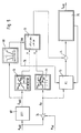
- the brake system according to the invention shown in Fig. 1 for Motor vehicles essentially consist of one Actuating unit 1, an electronic vehicle controller 6, Wheel brakes 10, 11, 12, 13, one between wheel brakes 10 to 13 and actuating unit 1 arranged pressure modulator 9 and an ABS / ASR controller interacting with the vehicle controller 6 7, the control signals for the pressure modulator 9 generated.
- Each of the vehicle wheels, not shown, is one Wheel sensor 14, 15, 16, 17, assigned to which the wheel speed corresponding control signal to the ABS / ASR controller 7 is fed.
- the actuating unit 1 is in turn from an actuatable by means of an actuation pedal 4 pneumatic brake booster, preferably one Vacuum brake booster 2, which is a master brake cylinder 3, preferably a tandem master cylinder, is connected downstream, its pressure rooms, not shown, via hydraulic lines 23, 27 are connected to the pressure modulator 9.
- an actuating rod 5 is coupled, the actuation of a merely shown schematically
- Control valve 19 allows the construction of a pneumatic differential pressure in the housing of the vacuum brake booster 2 controls.
- An electromagnet 20 enables external actuation of the control valve 19.
- the vehicle controller 6 is followed by a second electronic controller (brake pressure controller) 8, which has a control difference p formed in a first summer 24 between a target signal generated by the vehicle controller 6 based on, for example, an input signal E supplied by a distance sensor -Bremsdrucksignal p set and an actual braking pressure signal is p, the operation of the unit 1 or a prevailing in the master brake cylinder 3 pressure sensing pressure sensor is supplied 26th
- the output signal S AW of the brake pressure regulator 8 corresponds to the desired position or position of the armature of the electromagnet 20 actuating the control valve 19 to be set.
- a position on the control valve 19 can be determined in a second summer 25, for example by means of a displacement sensor (not shown)
- Control valve position actual value s is subtracted and the resulting control difference W is fed to a subordinate third controller (control valve position controller (18)), whose manipulated variable Y is used to control the electromagnet 20.
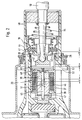
- control valve 19 is in one sealed in the housing of the brake booster 2 guided control housing 40 housed and consists of a first sealing seat 41 formed on the control housing 40, one connected to the actuating rod 5 Valve piston 42 formed second sealing seat 43 and one interacting with both sealing seats 41, 43 Valve body 44.
- a third sealing seat 28 is provided which by means of Electromagnet 20 can be actuated, which is preferably in one through an axial cup-shaped extension of the valve piston 42 formed housing 37 arranged and therefore together with the valve piston 42 is displaceable in the control housing 40.
- the electromagnet 20 consists of one on an inside of the housing 37 attached guide member 38 attached Coil 46 and a slidably disposed therein cylindrical anchor 39, which is insoluble with a pin 45 is connected, on the one hand in the guide part 38 and on the other hand, in a housing 37 that closes the housing Closure part 47 is guided.
- An the anchor 39 am Guide part 38 formed axially opposite The pole face can preferably be designed as an outer cone be a linearization of the force-displacement characteristic to reach the electromagnet 20.
- a Power transmission plate 48 which is preferably rectangular formed and in a radial groove 49 of the valve piston 42 is arranged and a transmission of the Electromagnet 20 applied external actuating force enables the third sealing seat 28.
- the third sealing seat 28 is sealed for this purpose on one in the control housing 40 guided sleeve 29 formed with the Power transmission plate 48 is connected.
- a compression spring 51 is arranged, which holds the anchor 39 in its starting position, in which the third sealing seat 28 compared to that on the valve piston 42 trained second sealing seat 43 axially offset (s. Distance b) is arranged.
- the anchor 39 After switching off the electromagnet 20 moves the anchor 39 with the third sealing seat 28 under the action the spring 51 to the left, whereby the third sealing seat 28 is opened while the valve body 44 the second Seal seat 43 closes. Since the first sealing seat 41 - as above mentioned - remains open, is about the open Connection between the pneumatic chambers from the ventilated chamber aspirated the atmosphere so that the im Master brake cylinder 3 prevailing pressure is reduced.
- the ventilated Chamber vented until the control group in their Starting position returns and the cross member 52 on the housing of the Brake booster 2 strikes.
- the control housing 40 can move until it is on the in the drawing left side of the cross member 52 comes to rest and the first sealing seat 41 is closed. The device is then in Release position.
- the basic structure of the brake pressure regulator 8 according to the invention shown in FIG. 3 shows that it is formed by a parallel connection of a first or follow-up regulator 21 and a second or final value regulator 22, which is followed by a situational changeover logic 55.
- Both controllers 21, 22 each meet the requirements, but have weaknesses in the complementary requirement. These weaknesses are compensated for by the situational switchover logic 55 which, depending on the determined control situation or a criterion explained later, switches through the output variable S Soll1 of the slave controller 21 or the output variable S Soll2 of the final value controller 22 to the subordinate position controller 18.
- the final value controller 22 comes into the control loop.
- the control structure shown in Fig. 4 consists in essentially from a position pilot branch 56, 57 and 58, the situational switching logic 61, 62 and 63, a non-linear transmission element 64 with a Three-point characteristic, a proportional - integrating (PI) controller 60 and a restriction logic 66.
- PI proportional - integrating
- the position control branch in turn consists of a differentiating (DT1) filter 56, to which the input signal is supplied the signal P soll corresponding to the target brake pressure value, a dead zone 57 which only contains the values of the filtered target pressure gradient p ⁇ formed in the DT1 filter 56 is to switch through that fall below or exceed a certain threshold, and an amplifier 58, the output variable S V of which is fed to a summer 59.
- DT1 differentiating
- the switching logic is p by a three-point element 61, possibly with hysteresis for detecting the sign of the nominal braking pressure gradient ⁇ is to a limit 62 with an additional reinforcement for the normalization of the control difference .DELTA.p formed in the first summer 24 and a map 63 formed, the the output signals y, x of the function blocks 61 and 62 are supplied as input variables, which are used as coordinates for selecting a value which is supplied to the non-linear transmission element 64, the three states (-1,0,1) of which a pressure increase or - degradation and a pressure maintenance phase.
- the output variable S VR of the nonlinear transmission element 64 is added in the summer 59 to the output variable S V of the precontrol, the addition result being added in a third summer 65 to the output variable S R of the PI controller 60 and subsequently being limited to realizable values in a restriction logic 66 , which simultaneously controls the I component of the PI controller 60.
- the previously mentioned slave controller 21 therefore essentially consists of the pilot branch 56, 57, 58, the non-linear transmission element 64 and the PI controller 60, while the final value regulator 22 by combining the limitation 62 with the characteristic map 63, the non-linear transmission element 64 and the PI controller 60 is formed.
- the output variable y assumes the value of a "1", which serves as a corresponding coordinate for the map 63, provided that the value of the signal mentioned exceeds the switching threshold specified by the three-point link 61.
- a signal y a corresponding to a "1" appears at the output of the map 63, irrespective of the size of the other coordinate x that is supplied by the limitation 62 and in this case for the Map 63 remains ineffective.
- a signal S VR then appears at the output of the transmission element 64, which represents an anchor path that is required for the pressure build-up. This signal is then added in summer 59 to the previously mentioned output signal of the pilot control S V.
- control difference ⁇ p 0 before the start of the setpoint change.
- control difference ⁇ p 0 again.
- the output variable S R is added in a further summer 65 to the result of the addition carried out in the summer 59, the end result of the addition being fed to a restriction logic 66, the output variable S should correspond to the desired armature travel and also the I component of the PI controller 60 controlled or limited.
- a P controller 78 can be used, which is preceded by a second differentiating (DT1) filter 77.
- the control structure shown in Fig. 5 consists in essentially from a differentiating (DT1) filter 68, a signal conditioning 69, a pilot control 70, a non-linear controller 71 with a three-point characteristic, one Weighting 72 and a PI controller 73 with a downstream restriction logic 75.
- DT1 filter is connected upstream.
- the target brake pressure gradient p ⁇ should representing output of the DT1 filter 68 is on the one hand fed as an input variable of the signal processing 69 and the other part of the pilot control 70th
- the control difference .DELTA.p which arises in the previously mentioned summer 24 serves as an input variable on the one hand for the non-linear controller 71 and on the other hand for the PI controller 73.
- the signal conditioning 69 generates a control signal SW for the weighting 72 as a function of a characteristic curve stored therein, which uses the output signals Y as input variables , X of the feedforward control 70 and of the non-linear controller 71 are supplied and the output quantity thereof corresponds to a combination of the output signals, which according to the formula X * (1-SW) + Y * SW is formed.
- the output signal Y of the feedforward control 70 is supplied by the DT1-filter 68 nominal brake pressure gradient p ⁇ is to assigned, while the output signal X generated by the processing of the control difference Ap in the nonlinear controller or modified three-point switch 71st
- the signal path designated by reference numeral 76 in FIG. 5 indicates that the parameters of the PI controller 73 by the Signal conditioning 69 are influenced or changed can.
- the previously mentioned slave controller 21 therefore consists in essentially from the differentiating (DT1) filter 68, the Precontrol 70, which is the switching logic 55 mentioned at the outset forming weighting 72 and the parallel connected PI controller 73, while the final value controller 22 by the Combination of the non-linear controller 71 with the weighting 72 and the PI controller 73 is formed.
- Weighting 72 elements of the fuzzy logic with has appropriate rules. This measure would a non-linear sliding change between the control modes as a function of target pressure, gradient, control difference and gradient reached.
Landscapes
- Physics & Mathematics (AREA)
- Engineering & Computer Science (AREA)
- Fluid Mechanics (AREA)
- Transportation (AREA)
- Mechanical Engineering (AREA)
- Electromagnetism (AREA)
- Braking Systems And Boosters (AREA)
- Regulating Braking Force (AREA)
Applications Claiming Priority (3)
| Application Number | Priority Date | Filing Date | Title |
|---|---|---|---|
| DE19511694A DE19511694A1 (de) | 1995-03-30 | 1995-03-30 | Bremsanlage für Kraftfahrzeuge |
| DE19511694 | 1995-03-30 | ||
| PCT/EP1996/001292 WO1996030239A1 (de) | 1995-03-30 | 1996-03-23 | Bremsanlage für kraftfahrzeuge |
Publications (2)
| Publication Number | Publication Date |
|---|---|
| EP0814982A1 EP0814982A1 (de) | 1998-01-07 |
| EP0814982B1 true EP0814982B1 (de) | 1999-06-23 |
Family
ID=7758168
Family Applications (1)
| Application Number | Title | Priority Date | Filing Date |
|---|---|---|---|
| EP96909120A Expired - Lifetime EP0814982B1 (de) | 1995-03-30 | 1996-03-23 | Bremsanlage für kraftfahrzeuge |
Country Status (6)
| Country | Link |
|---|---|
| US (1) | US6048039A (cs) |
| EP (1) | EP0814982B1 (cs) |
| CZ (1) | CZ306097A3 (cs) |
| DE (2) | DE19511694A1 (cs) |
| ES (1) | ES2132904T3 (cs) |
| WO (1) | WO1996030239A1 (cs) |
Families Citing this family (4)
| Publication number | Priority date | Publication date | Assignee | Title |
|---|---|---|---|---|
| WO2000024617A2 (de) * | 1998-10-27 | 2000-05-04 | Continental Teves Ag & Co. Ohg | Vorrichtung und verfahren zur bremskraftsteuerung einer bremsanlage |
| DE19858649C1 (de) * | 1998-12-18 | 2000-06-15 | Lucas Ind Plc | Elektronisch steuerbarer Bremskraftverstärker |
| JP3700523B2 (ja) * | 2000-02-25 | 2005-09-28 | 株式会社日立製作所 | 倍力装置の制御装置 |
| DE102015200106B3 (de) * | 2015-01-08 | 2016-05-12 | Ford Global Technologies, Llc | Steuerungsverfahren für ein hydraulisches Bremssystem eines Kraftfahrzeugs sowie hydraulisches Bremssystem |
Family Cites Families (16)
| Publication number | Priority date | Publication date | Assignee | Title |
|---|---|---|---|---|
| US3795426A (en) * | 1973-03-30 | 1974-03-05 | Bendix Corp | Actuation means responsive to a sensed braking condition for activating a servomotor |
| DE2951755A1 (de) * | 1979-12-21 | 1981-07-02 | Alfred Teves Gmbh, 6000 Frankfurt | Verfahren und schaltungsanordnung zur umwandlung von in fahrzeugen vorliegenden und als frequenz dargestellten veraenderlichen physikalischen groessen in zur frequenz proportionale zahlenwerte bzw. signale |
| DE3603810A1 (de) * | 1986-02-07 | 1987-08-13 | Bosch Gmbh Robert | Regeleinrichtung |
| DE4017429C2 (de) * | 1989-05-31 | 1996-05-30 | Honda Motor Co Ltd | Steuervorrichtung für die Bewegung eines Fahrzeuges |
| DE4213710A1 (de) * | 1992-04-25 | 1993-10-28 | Bosch Gmbh Robert | Blockierschutz- und Antriebsschlupf-Regelsystem |
| DE4234041C1 (de) * | 1992-10-09 | 1994-03-17 | Daimler Benz Ag | Bremsdruck-Steuereinrichtung für ein Straßenfahrzeug |
| DE4309244A1 (de) * | 1993-03-23 | 1994-09-29 | Teves Gmbh Alfred | Bremsanlage mit Blockierschutz- und/oder Antriebsschlupfregelung |
| DE4324205A1 (de) * | 1993-07-19 | 1995-01-26 | Teves Gmbh Alfred | Bremsanlage für Kraftfahrzeuge |
| DE4340921B4 (de) * | 1993-12-01 | 2004-11-18 | Robert Bosch Gmbh | Bremsdruckregelsystem |
| DE4405092C1 (de) * | 1994-02-17 | 1994-12-22 | Lucas Ind Plc | Pneumatischer Kraftverstärker mit elektromagnetischer Hilfssteuerung, insbesondere für Kraftfahrzeug-Bremsanlagen |
| DE4409909C2 (de) * | 1994-03-23 | 2003-11-27 | Continental Teves Ag & Co Ohg | Schaltungsanordnung für eine Bremsanlage mit elektronischer Regelung |
| DE4418444C2 (de) * | 1994-05-26 | 1999-01-14 | Lucas Ind Plc | Elektronisch regelbarer Bremskraftverstärker für eine Fahrzeugbremsanlage |
| DE4430461A1 (de) * | 1994-08-27 | 1996-02-29 | Teves Gmbh Alfred | Verfahren zur Steuerung des Bremsdrucks in Abhängigkeit von der Pedalbetätigungsgeschwindigkeit |
| DE19503202C1 (de) * | 1995-02-02 | 1996-04-04 | Daimler Benz Ag | Verfahren zum Beenden eines automatischen Bremsvorganges |
| JP3811972B2 (ja) * | 1995-10-30 | 2006-08-23 | アイシン精機株式会社 | 自動車用制動液圧制御装置 |
| DE69602002T2 (de) * | 1996-04-03 | 1999-09-30 | Lucas Industries P.L.C., Solihull | Elektronisch gesteuerter Bremskraftverstärker |
-
1995
- 1995-03-30 DE DE19511694A patent/DE19511694A1/de not_active Withdrawn
-
1996
- 1996-02-23 US US08/930,539 patent/US6048039A/en not_active Expired - Fee Related
- 1996-03-23 ES ES96909120T patent/ES2132904T3/es not_active Expired - Lifetime
- 1996-03-23 DE DE59602282T patent/DE59602282D1/de not_active Expired - Fee Related
- 1996-03-23 CZ CZ973060A patent/CZ306097A3/cs unknown
- 1996-03-23 WO PCT/EP1996/001292 patent/WO1996030239A1/de not_active Ceased
- 1996-03-23 EP EP96909120A patent/EP0814982B1/de not_active Expired - Lifetime
Also Published As
| Publication number | Publication date |
|---|---|
| WO1996030239A1 (de) | 1996-10-03 |
| EP0814982A1 (de) | 1998-01-07 |
| CZ306097A3 (cs) | 1998-03-18 |
| ES2132904T3 (es) | 1999-08-16 |
| DE59602282D1 (de) | 1999-07-29 |
| DE19511694A1 (de) | 1996-10-02 |
| US6048039A (en) | 2000-04-11 |
Similar Documents
| Publication | Publication Date | Title |
|---|---|---|
| DE4208496C1 (cs) | ||
| EP2580096B1 (de) | Verfahren und regelschaltung zur regelung eines bremssystems für kraftfahrzeuge | |
| EP0435113B1 (de) | Fahrzeugbremsanlage | |
| WO1995003196A1 (de) | Bremsanlage für kraftfahrzeuge | |
| EP3678909B1 (de) | Elektropneumatische parkbremssteuereinrichtung und bremsanlage eines fahrzeugs | |
| DE19738690C2 (de) | Verfahren und Vorrichtung zur Steuerung der Bremsanlage eines Fahrzeugs | |
| DE4436297C2 (de) | Elektronisch gesteuerter Bremskraftverstärker und Verfahren zu dessen Betrieb | |
| EP1478557B1 (de) | Verfahren zum einregeln eines vorgegebenen veränderlichen bremsdruckes | |
| EP2305524B2 (de) | Verfahren zum Betrieb einer Bremseinrichtung für ein hydraulisch gebremstes Zugfahrzeug | |
| EP0669565A2 (de) | Druckregeleinrichtung | |
| EP0814990A1 (de) | Bremsanlage für kraftfahrzeuge | |
| DE4406128C1 (de) | Verfahren zur Durchführung eines automatischen Bremsvorgangs für eine Kraftfahrzeug-Bremsanlage mit einem Antiblockiersystem | |
| EP0697317A1 (de) | Verfahren und Einrichtung zur Druckregelung | |
| EP3354527A1 (de) | Verfahren zum einstellen von bremsdrücken eines kraftfahrzeugs über ansteuerung eines drucksteuerventils, bremsanlage zur durchführung des verfahrens sowie kraftfahrzeug | |
| DE19615805A1 (de) | Verfahren und Vorrichtung zur Steuerung der Bremsanlage eines Fahrzeugs | |
| DE19514382A1 (de) | Bremsanlage für Kraftfahrzeuge | |
| EP0906211A1 (de) | Bremsanlage für kraftfahrzeuge | |
| EP0760765B1 (de) | Verfahren zum regeln des bremsdruckes | |
| DE69621760T2 (de) | Bremssteuergerät für Fahrzeuge | |
| EP0814982B1 (de) | Bremsanlage für kraftfahrzeuge | |
| DE4214547A1 (de) | Fahrzeugbremssystem | |
| DE19624794A1 (de) | Bremsanlage für Kraftfahrzeuge | |
| EP1140597B1 (de) | Elektronisch steuerbarer bremskraftverstärker | |
| DE19511844A1 (de) | Verfahren zum Betrieb eines Bremskraftverstärkers | |
| DE19940252A1 (de) | Vorrichtung und Verfahren zur Bremskraftsteuerung einer Bremsanlage |
Legal Events
| Date | Code | Title | Description |
|---|---|---|---|
| PUAI | Public reference made under article 153(3) epc to a published international application that has entered the european phase |
Free format text: ORIGINAL CODE: 0009012 |
|
| 17P | Request for examination filed |
Effective date: 19971030 |
|
| AK | Designated contracting states |
Kind code of ref document: A1 Designated state(s): DE ES FR GB |
|
| GRAG | Despatch of communication of intention to grant |
Free format text: ORIGINAL CODE: EPIDOS AGRA |
|
| 17Q | First examination report despatched |
Effective date: 19980402 |
|
| GRAG | Despatch of communication of intention to grant |
Free format text: ORIGINAL CODE: EPIDOS AGRA |
|
| GRAH | Despatch of communication of intention to grant a patent |
Free format text: ORIGINAL CODE: EPIDOS IGRA |
|
| GRAH | Despatch of communication of intention to grant a patent |
Free format text: ORIGINAL CODE: EPIDOS IGRA |
|
| RAP1 | Party data changed (applicant data changed or rights of an application transferred) |
Owner name: CONTINENTAL TEVES AG & CO. OHG |
|
| GRAA | (expected) grant |
Free format text: ORIGINAL CODE: 0009210 |
|
| AK | Designated contracting states |
Kind code of ref document: B1 Designated state(s): DE ES FR GB |
|
| GBT | Gb: translation of ep patent filed (gb section 77(6)(a)/1977) |
Effective date: 19990623 |
|
| REF | Corresponds to: |
Ref document number: 59602282 Country of ref document: DE Date of ref document: 19990729 |
|
| REG | Reference to a national code |
Ref country code: ES Ref legal event code: FG2A Ref document number: 2132904 Country of ref document: ES Kind code of ref document: T3 |
|
| ET | Fr: translation filed | ||
| PG25 | Lapsed in a contracting state [announced via postgrant information from national office to epo] |
Ref country code: GB Free format text: LAPSE BECAUSE OF NON-PAYMENT OF DUE FEES Effective date: 20000323 |
|
| PG25 | Lapsed in a contracting state [announced via postgrant information from national office to epo] |
Ref country code: ES Free format text: LAPSE BECAUSE OF NON-PAYMENT OF DUE FEES Effective date: 20000324 |
|
| PLBE | No opposition filed within time limit |
Free format text: ORIGINAL CODE: 0009261 |
|
| STAA | Information on the status of an ep patent application or granted ep patent |
Free format text: STATUS: NO OPPOSITION FILED WITHIN TIME LIMIT |
|
| 26N | No opposition filed | ||
| GBPC | Gb: european patent ceased through non-payment of renewal fee |
Effective date: 20000323 |
|
| PG25 | Lapsed in a contracting state [announced via postgrant information from national office to epo] |
Ref country code: DE Free format text: LAPSE BECAUSE OF NON-PAYMENT OF DUE FEES Effective date: 20010103 |
|
| PG25 | Lapsed in a contracting state [announced via postgrant information from national office to epo] |
Ref country code: FR Free format text: LAPSE BECAUSE OF NON-PAYMENT OF DUE FEES Effective date: 20010531 |
|
| REG | Reference to a national code |
Ref country code: FR Ref legal event code: ST |
|
| REG | Reference to a national code |
Ref country code: FR Ref legal event code: RN Ref country code: FR Ref legal event code: D3 |
|
| REG | Reference to a national code |
Ref country code: ES Ref legal event code: FD2A Effective date: 20010411 |
|
| PG25 | Lapsed in a contracting state [announced via postgrant information from national office to epo] |
Ref country code: FR Free format text: LAPSE BECAUSE OF NON-PAYMENT OF DUE FEES Effective date: 20000331 |