EP0815895A1 - Appareil medical tubulaire - Google Patents
Appareil medical tubulaire Download PDFInfo
- Publication number
- EP0815895A1 EP0815895A1 EP97401225A EP97401225A EP0815895A1 EP 0815895 A1 EP0815895 A1 EP 0815895A1 EP 97401225 A EP97401225 A EP 97401225A EP 97401225 A EP97401225 A EP 97401225A EP 0815895 A1 EP0815895 A1 EP 0815895A1
- Authority
- EP
- European Patent Office
- Prior art keywords
- tubular body
- lumen
- distal end
- compression
- wire
- Prior art date
- Legal status (The legal status is an assumption and is not a legal conclusion. Google has not performed a legal analysis and makes no representation as to the accuracy of the status listed.)
- Granted
Links
- 239000000463 material Substances 0.000 claims description 13
- 238000011282 treatment Methods 0.000 claims description 7
- 238000004804 winding Methods 0.000 claims description 2
- 230000006835 compression Effects 0.000 abstract description 4
- 238000007906 compression Methods 0.000 abstract description 4
- 210000000056 organ Anatomy 0.000 description 21
- -1 polyethylene Polymers 0.000 description 16
- 239000000835 fiber Substances 0.000 description 12
- 230000002787 reinforcement Effects 0.000 description 12
- 239000013307 optical fiber Substances 0.000 description 10
- 238000003780 insertion Methods 0.000 description 9
- 230000037431 insertion Effects 0.000 description 9
- 238000005452 bending Methods 0.000 description 8
- 239000012530 fluid Substances 0.000 description 7
- 229910001220 stainless steel Inorganic materials 0.000 description 7
- 229910045601 alloy Inorganic materials 0.000 description 6
- 239000000956 alloy Substances 0.000 description 6
- 239000004952 Polyamide Substances 0.000 description 4
- 239000004698 Polyethylene Substances 0.000 description 4
- 210000004204 blood vessel Anatomy 0.000 description 4
- 210000001124 body fluid Anatomy 0.000 description 4
- 239000010839 body fluid Substances 0.000 description 4
- 238000000034 method Methods 0.000 description 4
- 229920002647 polyamide Polymers 0.000 description 4
- 229920000573 polyethylene Polymers 0.000 description 4
- 229920005989 resin Polymers 0.000 description 4
- 239000011347 resin Substances 0.000 description 4
- 239000010935 stainless steel Substances 0.000 description 4
- 239000004642 Polyimide Substances 0.000 description 3
- 239000004743 Polypropylene Substances 0.000 description 3
- 239000000853 adhesive Substances 0.000 description 3
- 238000002674 endoscopic surgery Methods 0.000 description 3
- 239000000945 filler Substances 0.000 description 3
- 238000002347 injection Methods 0.000 description 3
- 239000007924 injection Substances 0.000 description 3
- 229910052751 metal Inorganic materials 0.000 description 3
- 239000002184 metal Substances 0.000 description 3
- 229920000728 polyester Polymers 0.000 description 3
- 229920001721 polyimide Polymers 0.000 description 3
- 229920001155 polypropylene Polymers 0.000 description 3
- 239000004810 polytetrafluoroethylene Substances 0.000 description 3
- 229920001343 polytetrafluoroethylene Polymers 0.000 description 3
- 229940058401 polytetrafluoroethylene Drugs 0.000 description 3
- 229920000049 Carbon (fiber) Polymers 0.000 description 2
- 229910000963 austenitic stainless steel Inorganic materials 0.000 description 2
- TZCXTZWJZNENPQ-UHFFFAOYSA-L barium sulfate Chemical compound [Ba+2].[O-]S([O-])(=O)=O TZCXTZWJZNENPQ-UHFFFAOYSA-L 0.000 description 2
- 239000004917 carbon fiber Substances 0.000 description 2
- 238000004519 manufacturing process Methods 0.000 description 2
- VNWKTOKETHGBQD-UHFFFAOYSA-N methane Chemical compound C VNWKTOKETHGBQD-UHFFFAOYSA-N 0.000 description 2
- 238000012986 modification Methods 0.000 description 2
- 230000004048 modification Effects 0.000 description 2
- BASFCYQUMIYNBI-UHFFFAOYSA-N platinum Chemical compound [Pt] BASFCYQUMIYNBI-UHFFFAOYSA-N 0.000 description 2
- 229920000915 polyvinyl chloride Polymers 0.000 description 2
- 239000004800 polyvinyl chloride Substances 0.000 description 2
- 229920002379 silicone rubber Polymers 0.000 description 2
- 239000004945 silicone rubber Substances 0.000 description 2
- 239000007787 solid Substances 0.000 description 2
- 239000000126 substance Substances 0.000 description 2
- WFKWXMTUELFFGS-UHFFFAOYSA-N tungsten Chemical compound [W] WFKWXMTUELFFGS-UHFFFAOYSA-N 0.000 description 2
- 229910052721 tungsten Inorganic materials 0.000 description 2
- 239000010937 tungsten Substances 0.000 description 2
- 230000000007 visual effect Effects 0.000 description 2
- 239000004925 Acrylic resin Substances 0.000 description 1
- 229920000178 Acrylic resin Polymers 0.000 description 1
- 229910000975 Carbon steel Inorganic materials 0.000 description 1
- 229910017518 Cu Zn Inorganic materials 0.000 description 1
- 229910000881 Cu alloy Inorganic materials 0.000 description 1
- 229910017755 Cu-Sn Inorganic materials 0.000 description 1
- 229910017752 Cu-Zn Inorganic materials 0.000 description 1
- 229910017927 Cu—Sn Inorganic materials 0.000 description 1
- 229910017943 Cu—Zn Inorganic materials 0.000 description 1
- WQZGKKKJIJFFOK-GASJEMHNSA-N Glucose Chemical compound OC[C@H]1OC(O)[C@H](O)[C@@H](O)[C@@H]1O WQZGKKKJIJFFOK-GASJEMHNSA-N 0.000 description 1
- VYPSYNLAJGMNEJ-UHFFFAOYSA-N Silicium dioxide Chemical compound O=[Si]=O VYPSYNLAJGMNEJ-UHFFFAOYSA-N 0.000 description 1
- 229910000831 Steel Inorganic materials 0.000 description 1
- 210000000683 abdominal cavity Anatomy 0.000 description 1
- 238000005299 abrasion Methods 0.000 description 1
- 229920000122 acrylonitrile butadiene styrene Polymers 0.000 description 1
- 230000001070 adhesive effect Effects 0.000 description 1
- 239000004411 aluminium Substances 0.000 description 1
- 229910052782 aluminium Inorganic materials 0.000 description 1
- XAGFODPZIPBFFR-UHFFFAOYSA-N aluminium Chemical compound [Al] XAGFODPZIPBFFR-UHFFFAOYSA-N 0.000 description 1
- 210000000941 bile Anatomy 0.000 description 1
- 230000005540 biological transmission Effects 0.000 description 1
- 229910000416 bismuth oxide Inorganic materials 0.000 description 1
- 239000008280 blood Substances 0.000 description 1
- 210000004369 blood Anatomy 0.000 description 1
- 238000009954 braiding Methods 0.000 description 1
- 239000010962 carbon steel Substances 0.000 description 1
- 230000000747 cardiac effect Effects 0.000 description 1
- 239000003638 chemical reducing agent Substances 0.000 description 1
- 229920001577 copolymer Polymers 0.000 description 1
- KUNSUQLRTQLHQQ-UHFFFAOYSA-N copper tin Chemical compound [Cu].[Sn] KUNSUQLRTQLHQQ-UHFFFAOYSA-N 0.000 description 1
- TVZPLCNGKSPOJA-UHFFFAOYSA-N copper zinc Chemical compound [Cu].[Zn] TVZPLCNGKSPOJA-UHFFFAOYSA-N 0.000 description 1
- 238000005520 cutting process Methods 0.000 description 1
- 230000002380 cytological effect Effects 0.000 description 1
- 230000007423 decrease Effects 0.000 description 1
- 230000003247 decreasing effect Effects 0.000 description 1
- 238000003745 diagnosis Methods 0.000 description 1
- TYIXMATWDRGMPF-UHFFFAOYSA-N dibismuth;oxygen(2-) Chemical compound [O-2].[O-2].[O-2].[Bi+3].[Bi+3] TYIXMATWDRGMPF-UHFFFAOYSA-N 0.000 description 1
- 239000003822 epoxy resin Substances 0.000 description 1
- 239000005038 ethylene vinyl acetate Substances 0.000 description 1
- 238000002594 fluoroscopy Methods 0.000 description 1
- 239000011521 glass Substances 0.000 description 1
- 239000003365 glass fiber Substances 0.000 description 1
- 229920001477 hydrophilic polymer Polymers 0.000 description 1
- KHYBPSFKEHXSLX-UHFFFAOYSA-N iminotitanium Chemical compound [Ti]=N KHYBPSFKEHXSLX-UHFFFAOYSA-N 0.000 description 1
- LIKBJVNGSGBSGK-UHFFFAOYSA-N iron(3+);oxygen(2-) Chemical compound [O-2].[O-2].[O-2].[Fe+3].[Fe+3] LIKBJVNGSGBSGK-UHFFFAOYSA-N 0.000 description 1
- 239000007788 liquid Substances 0.000 description 1
- 239000003550 marker Substances 0.000 description 1
- 150000002739 metals Chemical class 0.000 description 1
- 229910001000 nickel titanium Inorganic materials 0.000 description 1
- 210000004798 organs belonging to the digestive system Anatomy 0.000 description 1
- 230000000399 orthopedic effect Effects 0.000 description 1
- 210000000277 pancreatic duct Anatomy 0.000 description 1
- 230000000704 physical effect Effects 0.000 description 1
- 229920003023 plastic Polymers 0.000 description 1
- 239000004033 plastic Substances 0.000 description 1
- 229910052697 platinum Inorganic materials 0.000 description 1
- 229920001200 poly(ethylene-vinyl acetate) Polymers 0.000 description 1
- 229920000647 polyepoxide Polymers 0.000 description 1
- 229920000642 polymer Polymers 0.000 description 1
- 229920002635 polyurethane Polymers 0.000 description 1
- 239000004814 polyurethane Substances 0.000 description 1
- 238000004881 precipitation hardening Methods 0.000 description 1
- 230000000241 respiratory effect Effects 0.000 description 1
- 238000007788 roughening Methods 0.000 description 1
- 239000012266 salt solution Substances 0.000 description 1
- 239000000523 sample Substances 0.000 description 1
- 230000035939 shock Effects 0.000 description 1
- 239000000243 solution Substances 0.000 description 1
- 239000010959 steel Substances 0.000 description 1
- 210000003708 urethra Anatomy 0.000 description 1
- 238000005406 washing Methods 0.000 description 1
- XLYOFNOQVPJJNP-UHFFFAOYSA-N water Substances O XLYOFNOQVPJJNP-UHFFFAOYSA-N 0.000 description 1
Images




Classifications
-
- A—HUMAN NECESSITIES
- A61—MEDICAL OR VETERINARY SCIENCE; HYGIENE
- A61M—DEVICES FOR INTRODUCING MEDIA INTO, OR ONTO, THE BODY; DEVICES FOR TRANSDUCING BODY MEDIA OR FOR TAKING MEDIA FROM THE BODY; DEVICES FOR PRODUCING OR ENDING SLEEP OR STUPOR
- A61M25/00—Catheters; Hollow probes
- A61M25/01—Introducing, guiding, advancing, emplacing or holding catheters
- A61M25/0105—Steering means as part of the catheter or advancing means; Markers for positioning
- A61M25/0133—Tip steering devices
- A61M25/0147—Tip steering devices with movable mechanical means, e.g. pull wires
-
- A—HUMAN NECESSITIES
- A61—MEDICAL OR VETERINARY SCIENCE; HYGIENE
- A61M—DEVICES FOR INTRODUCING MEDIA INTO, OR ONTO, THE BODY; DEVICES FOR TRANSDUCING BODY MEDIA OR FOR TAKING MEDIA FROM THE BODY; DEVICES FOR PRODUCING OR ENDING SLEEP OR STUPOR
- A61M25/00—Catheters; Hollow probes
- A61M25/01—Introducing, guiding, advancing, emplacing or holding catheters
- A61M25/0105—Steering means as part of the catheter or advancing means; Markers for positioning
- A61M25/0133—Tip steering devices
- A61M25/0144—Tip steering devices having flexible regions as a result of inner reinforcement means, e.g. struts or rods
-
- A—HUMAN NECESSITIES
- A61—MEDICAL OR VETERINARY SCIENCE; HYGIENE
- A61B—DIAGNOSIS; SURGERY; IDENTIFICATION
- A61B18/00—Surgical instruments, devices or methods for transferring non-mechanical forms of energy to or from the body
- A61B2018/0091—Handpieces of the surgical instrument or device
- A61B2018/00916—Handpieces of the surgical instrument or device with means for switching or controlling the main function of the instrument or device
-
- A—HUMAN NECESSITIES
- A61—MEDICAL OR VETERINARY SCIENCE; HYGIENE
- A61M—DEVICES FOR INTRODUCING MEDIA INTO, OR ONTO, THE BODY; DEVICES FOR TRANSDUCING BODY MEDIA OR FOR TAKING MEDIA FROM THE BODY; DEVICES FOR PRODUCING OR ENDING SLEEP OR STUPOR
- A61M25/00—Catheters; Hollow probes
- A61M25/01—Introducing, guiding, advancing, emplacing or holding catheters
- A61M25/0105—Steering means as part of the catheter or advancing means; Markers for positioning
- A61M25/0133—Tip steering devices
- A61M25/0147—Tip steering devices with movable mechanical means, e.g. pull wires
- A61M2025/015—Details of the distal fixation of the movable mechanical means
Definitions
- This invention relates to a tubular medical device designed for insertion into a body, for example a hollow organ or body cavity (heart, blood vessel, alimentary canal, urethra, abdominal cavity, etc.), for medical examination or treatment, and especially to a tubular medical device used for guiding an endoscope into a hollow organ or body cavity to examine.
- a hollow organ or body cavity herein, heart, blood vessel, alimentary canal, urethra, abdominal cavity, etc.
- Endoscopic surgery was generally in the field of digestive organs. It was then applied to the field of respiratory organ, ear/nose/throat, neurosurgery, obsterics and gynecology, and orthopedics.
- a small-diameter endoscope system used for endoscopic surgery comprises a catheter body which is inserted into the body of a patient and a control portion which an operator manipulates by hands.
- the catheter body is generally provided at the distal end portion with a mechanism which turns the distal end portion in an intended direction in order to make the distal end portion proceed along a curved or branched hollow organ (insertion path) or to view a different part of the organ.
- a method which connects two or more articulation rings movably in series and bends the distal end by pulling a wire (wires) is used.
- a tubular medical device which does not have articulation rings is proposed to meet the increasing request for a thinner endoscope.
- the tubular medical device has a closely wound coil with a compression resistance in the direction of the axis securely held in a lumen extending throughout the entire length of the tubular body except the distal end portion.
- This tubular medical device has a wire whose distal end is secured near the distal end of the tubular body away from the axis and which is passed through the compression-resisting member or another lumen.
- the distal end portion of this tubular medical device can be bent from outside the body by pulling the proximal end of the wire (Japanese Patent Application laid open under No. 94-343702).
- This tubular medical device is made so that only the distal end portion bends to pull on the wire, by putting a closely wound coil in the tubular body which resists compression in the direction of the axis.
- a lumen in which the closely wound coil is held is formed in the tubular body, then the closely wound coil is inserted into the lumen to the predetermined position, and the coil is secured in the lumen at some portions (distal end portions and proximal end portion of the coil, for example).
- the interior diameter of the lumen must be made a little larger than the exterior diameter of the coil, and hence a certain gap is inevitably formed between the inside wall of the lumen and the outside surface of the coil. Because of its very small exterior diameter of the coil and a gap between the inside wall of the lumen and the outside surface of the coil, the coil easily bends in the lumen to a small compressing force except the secured portions.
- the object of this invention is to solve the above problem, by providing an improved tubular medical device for insertion into a body only the distal end portion of which bends accurately according to the pulling force.
- the tubular medical device of this invention which comprises a tubular body, a lumen extending in almost entire length of said tubular body, and a compression-resisting member which is held in said lumen with a distal end positioned at a predetermined distance from a distal end of said tubular body to a proximal side and secured in said lumen so as not to move in a direction of an axis of said tubular body, a wire whose distal end is secured at a position in a wall of said tubular body close to said distal end of said tubular body and displaced from the axis of said tubular body and whose a proximal end is lead out of a proximal end of said tubular body, means for pulling said wire which is provided at the proximal side of said tubular body and operated to control a direction of a distal end portion of said tubular body by said wire.
- the said compression-resisting member comprises a major component which constitutes an essential part of said compression-
- Figure 1 is a perspective view of the whole body of an embodiment of the tubular medical device of this invention applied to an endoscope (fiberscope).
- endoscope fiberscope
- Figure 2 is a perspective view of the distal end portion of the tubular medical device shown in Figure 1.
- Figure 3 is a front view of the distal end portion of the tubular medical device shown in Figure 1.
- Figure 4 is a sectional view along line I-I in Figure 3.
- Figure 5 is a sectional view along line II-II in Figure 3.
- Figure 6 is a sectional view along line III-III in Figure 3.
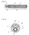
- Figure 7 is a diagrammatic view showing the structure in cross-section of the tubular medical device.
- Figure 8 is a sectional view along line IV-IV in Figure 6.
- Figure 9 is a sectional view along line V-V in Figure 6.
- Figure 10 is an enlarged perspective view of a compression-resisting member used in the tubular medical device of this invention.
- Figure 11 is an enlarged perspective view of an another compression-resisting member used in the tubular medical device of this invention.
- Figure 1 is a perspective view of the whole body of an embodiment of the tubular medical device of this invention which is applied to an endoscope (fiberscope).
- Figure 2 is a perspective view of the distal end portion of the tubular medical device shown in Figure 1.
- Figure 3 is a front view of the distal end portion of the tubular medical device shown in Figure 1.
- Figure 4 is a sectional view along line I-I in Figure 2.
- Figure 5 is a sectional view along line II-II in Figure 3.
- Figure 6 is a sectional view along line III-III in Figure 3.
- the right side end of the endoscope is referred to as the proximal end, and the left side end as the distal end.
- the tubular medical device 1 of this invention is a tubular medical device for insertion into hollow organs, for example blood vessel, and may also be called a catheter tube.
- the tubular medical device 1 for insertion into a body comprises a tubular body 2, a lumen 42 extending in the almost entire length of the tubular body 2, an compression-resisting member 7 inserted in the lumen 42 so that it cannot move in the direction of the axis of the tubular body 2, with its distal end located at a predetermined distance from the distal end of the tubular body 2 toward the proximal end, a pull wire 5 whose distal end is secured near the distal end of the tubular body 2 at a position deviated from the axis of the tubular body 2 and which is led in the tubular body 2 to the proximal end of the tubular body 2, and a pulling mechanism for pulling the pull wire 5 toward the proximal end of the tubular body which is attached to the proximal end of the tubular body 2 and has an manipulation dial 106.
- the tubular medical device 1 is constructed so that the distal end portion (deformable portion) 21 of the tubular body 2 bends when the pull wire 5 is pulled toward the proximal end of the tubular body 2.
- the compression-resisting member 7 consists of a main body ( major portion ) 71 and a secured portion 72 as shown in Figures 6 to 10.
- the compression-resisting member main body 71 constitutes an almost entire part of the compression-resisting member 7, and has a property of resisting compression in the axial direction of the tubular body 2.
- the secured portion may be attached to the main body 71 or formed as one single part together with the main body 71.
- the secured portion retains the main part 71 in place in the lumen 42.
- the main body 71 ( major component) of the compression-resisting member 7 is formed of a long cylindrical or long substantially cylindrical member.
- the tubular medical device 1 of this invention has a tubular body 2.
- the tubular body 2 is formed of a polymer such as soft polyvinyl chloride, polyethylene, polypropylene, polyurethane, polyamide, polytetrafluoroethylene, silicone rubber, or ethylene-vinyl acetate copolymer.
- the tubular body 2 partly or entirely with a radiopaque property so that the tubular device is visible under fluoroscopy.
- a radiopaque substance such as barium sulfate, bismuth oxide, or tungsten
- the material of the tubular body 2 or embedding a marker made of a radiopaque substance as described above in the tubular body 2 or attaching the maker to the surface of the tubular body 2, for example.
- the outside surface of the tubular body 2 may be coated with a friction-reducing substance such as a hydrophilic polymer (maleic anhydride copolymer, for example) or a fluororesin (polytetrafluoroethylene, for example).
- a friction-reducing substance such as a hydrophilic polymer (maleic anhydride copolymer, for example) or a fluororesin (polytetrafluoroethylene, for example).
- a deformable portion (or bendable portion) 21 which bends according to later described wire pulling manipulation is formed.
- a manipulation grip 10 for making manipulation of bending the deformable portion 21 is attached.
- the middle part 22 of the tubular body 2 between the deformable portion 21 and the proximal end 23 has a certain flexibility such that, when the tubular medical device 1 is inserted into a hollow organ such as a blood vessel or the pancreatic duct, it bends following curved and angular parts of the hollow organ, but does not bend to later described wire pulling manipulation.
- a first lumen 42, second lumen 44, third lumen 43, and fourth lumen 41 are formed in the tubular body 2 through its almost entire length as shown in Figure 6.
- the fourth lumen 41 extends from the proximal end to the distal end of the tubular body 2 and is open in the distal end of the tubular body 2 as shown in Figure 6. This is, the fourth lumen 41 has an open end in the distal end of the tubular body 2.
- the first lumen 42, second lumen 44, and third lumen 43 extend from the proximal end of the tubular body 2 to near the distal end of the tubular body 2, with their distal end at a predetermined small distance from the distal end of the tubular body 2 toward the proximal side as shown in Figure 6.
- the distance between the distal end of the tubular body 2 and that of these lumens 42, 44, and 43 is preferably within the range of 1 to 2 mm.
- a fiber optics (a bundle of optical fibers) 9 for viewing inside the hollow organ into which the tubular medical device 1 is inserted is held in the fourth lumen 41.
- the fiber optics 9 is also used for medical treatment such as applying laser light to the inside wall of a hollow organ.
- the fiber optics 9 consists of light transmitting optical fibers (light guide) 91 and light receiving optical fibers (image guide) 92 as shown in Figures 4, 8 and 9.
- the fiber optics 9 is fabricated by embedding these optical fibers in a resin such as an epoxy resin, acrylic resin, or silicone rubber into a bundle.
- the light transmitting and receiving optical fibers 91 and 92 consist of optical fibers made of quartz glass, multicomponent glass, or plastic.
- the fiber optics 9 is equipped with a lens 93 for collecting the light reflected from an examined area in the distal end of the fiber optics 9, and the lens 93 is located near the opening of the distal end of the lumen 41 as shown in Figure 4.
- the fiber optics 9 is preferably fixed to the lumen 41, it may be slidable to the lumen 41 so that the distal end portion of the fiber optics 9 can be protruded from and retracted into the distal end opening of the lumen 41.
- the light generated by a light source (not shown) at the proximal side (right side in Figure 1) of the manipulating grip 10 is guided by the light transmitting optical fibers 91 and emitted from the distal end of the light transmitting optical fibers 92 to an examined area of the inside wall of an organ.
- the light reflected from the inside wall of the organ is collected by the lens 93 and enters the light receiving optical fibers 92 from the distal end.
- the light is then guided by the light receiving optical fibers 92 to an image display device (not shown) at the proximal side of the manipulating grip.
- the lumen 41 can be used to inject medical fluids into the hollow organ in which the tubular medical device 1 is inserted and left.
- the lumen 41 can also be used as a flashing channel to inject a transparent liquid (physiological salt solution or a solution of grape sugar, for example) for washing away body fluids such as blood and bile obstructing the view when examining the interior of a hollow organ by an endoscope.
- the lumen 41 can be used as a channel to pass a guide wire and devices for treatment or test such as forceps, cytological diagnosis brush, injection needle, lithodialysis probe which radiates high frequency electromagnetic waves, ultrasonic waves, or water pressure shock waves for breaking a blood stone, and various types of sensors and their lead wires.
- a guide wire and devices for treatment or test such as forceps, cytological diagnosis brush, injection needle, lithodialysis probe which radiates high frequency electromagnetic waves, ultrasonic waves, or water pressure shock waves for breaking a blood stone, and various types of sensors and their lead wires.
- the first lumen 42 and the second lumen 44 are used for holding an compression-resisting member 7 for preventing the middle part 22 and proximal end portion 23 of the tubular body 2 from bending to the pulling force to manipulate the deformable portion 21.
- the third lumen 43 is used to hold the wire 5 for bending the deformable portion 21.
- These lumens 42, 43, and 44 are disposed near the circumference of the cross section of the tubular body 2, close to each other, with the third lumen 43 between the first and second lumens 42 and 44 as shown in Figures 8 and 9. In other words, these lumens are disposed so that the distance between the first lumen 42 and the second lumen 44 is greater than the distance between the first lumen 42 and the third lumen 43 and that between the second lumen 44 and the third lumen 43.
- a compression-resisting member 7 is set in the portion of the lumens 42 and 44 located in the middle portion 22 and proximal portion 23 of the tubular body 2 as shown in Figure 6.
- the compression-resisting members 7 can also be called as compression-resisting supports.
- Each compression-resisting member 7 comprises a main body 71 which is not compressible in the direction of the axis (length).
- main bodies 71 of the compression-resisting members have secured portions 72a, 72b (or means for fixing the main body to the wall of the lumen), which are coils of a strip (flat wire) closely wound in a spiral substantially with a small gap between adjacent turns attached to their distal and proximal ends of each of main body 71 as shown in Figure 10.
- the coils may be made separately and attached to the main body 71, or may be formed as a single part together with the main body 71.
- the main bodies 71 of the compression-resisting members 7 are substantially not compressible in the direction of their length, and prevent the tubular body 2 from bending to the compressing force applied when the wire 5 is pulled.
- the main body 71 ( major component) of the compression-resisting member 7 is formed of a long cylindrical member.
- the main body 71 of the compression-resisting members 7 is a solid wire, as shown in an enlarged view in Figures 6 and 10.
- the compression-resisting members 7 are placed in the lumens 42 and 44 so that their main body 71 is positioned in the middle portion 22 of the tubular body 2.
- These main bodies 71 are provided with the secured portions 72a, 72b which are dosely wound coils of a flat wire at their distal and proximal ends.
- the main bodies 71 of the compression-resisting members 7 are made of a material which is not compressed in the direction of the length and have an appropriate flexibility to bend a certain amount.
- stainless steel austenitic stainless steel such as SUS304, SUS316, and SUS312; mulaging stainless steel; and precipitation hardening stainless steel, etc.
- super elastic alloy Ni-Ti alloy, etc.
- Cu-Zn alloy copper alloy (Cu-Sn, etc.)
- carbon steel tungsten steel, various elastic metals (aluminium, platinum, etc.), and various hard resins (polyamide, polyethylene, polypropylene, poly allylate, poly(vinyl chloride), polytetrafluoro-ethylene, polyester, polyimide, etc.)
- various hard resins polyamide, polyethylene, polypropylene, poly allylate, poly(vinyl chloride), polytetrafluoro-ethylene, polyester, polyimide, etc.
- the middle portion 22 of the tubular body 2 has an appropriate flexibility which makes insertion of the tubular medical device 1 into a hollow organ such as a blood vessel easy.
- the compression-resisting member main body 71 must not be a solid wire as shown in the Figures, and may be a hollow tube or pipe compression-resisting in the direction of the axis. When such a tube or pipe is used, the above described materials are preferable for the material of the tube or pipe.
- the secured portions 72a and 72b of this embodiment consist of a closely wound coil as shown in Figure 10, respectively.
- a strip or a wire is closely wound on the outside surface of the secured portions 72 so that there is a small gap between adjacent turns. As the result, the secured portions 72 have unevenness formed by the gaps.
- the secured portions 72a of the first and second compression-resisting members are positioned at or near the boundary 24 of the deformable portion 21 and the middle portion 22 of the tubular body 2 and fixed to the inside surface of the lumens 42 and 44 as shown in Figure 6.
- the secured portions 72b of the first and second compression-resisting members are positioned near the proximal end 23 of the tubular body 2 and fixed to the inside surface of the lumens 42 and 44.
- Fixing of the secured portions 72a and 72b to the inside surface of the lumens 42 and 44 can be made by the following method, for example.
- heat-shrinking tubes (not shown) are put on the tubular body 2 so as to cover the outside surface of the boundary region 24 and the proximal end portion 23.
- heat is applied to the heat-shrinking tubes to shrink them, and the shrunk tubes squeeze the tubular body 2. Because of this squeezing force, the inside wall of the lumens 42 an 44 is pressed to the secured portions 72a and 72b, and enters the gaps in the coils. As the result, the secured portions 72a and 72b are firmly held by the inside wall of the lumens 42 and 44.
- the compression-resisting members can be fixed in the lumens easily with a high reliability.
- the positions where secured portions 72 are attached to (or formed on) the main body 71 of the compression-resisting members 7 are not limited to the distal and proximal ends.
- one or more secured portions may be attached to (or formed on) the middle portion of the main body 71.
- the secured portions 72 may be fixed in the lumens by other methods.
- the secured portions 72 can be fixed in the lumens by putting squeezing sleeves (tubular pieces) which can be tightened by caulking on the tubular body 2 and caulking the sleeves. By the squeezing pressure of the caulked sleeves, the inside wall of the lumens is pressed to the outside surface of the secured portions 72 and enters the gaps in the winding of the coils.
- an adhesive agent may be applied between the outside surface of the secured portions 72 and the inside surface of the lumens 42, 44 to increase the reliability of fixing.
- Connection of the secured portions 72 to the compression-resisting member main body 71 can be made by bonding each secured portion 72 and the main portion 71 end to end with an adhesive agent (filler).
- the connection can also be made by forming the distal and proximal end portions of the main body 71 smaller in diameter, inserting each thinner portion into the opening of the coil of a secured portion, and bonding the outside surface of the thinner portion and the inside surface of the coil with an adhesive (filler).
- the lumens 42 and 44 are extended to in the deformable portion 21, and the region of the lumens 42 and 44 between their distal end and the distal-side end of the secured portion 72a is left vacant.
- the tubular medical device 1 has hollow spaces which extend in the bendable portion 21 as shown in Figure 6. Therefore, the deformable portion 21 can be bent easily by pulling the wire.
- the dimensions such as the exterior diameter of the compression-resisting member main body 71 vary according to the conditions such as the material of the main body 71 and the shape, dimensions of the cross section, and material of the tubular body 2.
- the exterior diameter is preferably within the range of 0.05 to 1.0 mm, and more preferably 0.3 to 0.35 mm.
- the interior diameter of the lumens 42 and 44 is preferably about 1.2 to 2.0, more preferably about 1.01 to 1.4 times the exterior diameter of the compression-resisting member main body 71. If the interior diameter of the lumens 42 and 44 is larger than 1.0 time the exterior diameter of the compression-resisting member main body 71, insertion of the compression-resisting member main bodies 71 into the lumens 42 and 44 is easy. If the interior diameter of the lumens 42 and 44 is smaller than twice the exterior diameter of the compression-resisting member main body 71, the exterior diameter of the tubular body 2 does not become too large, and the compression-resisting member main bodies 71 do not bend sinuously too much in the lumens 42 and 44. Further, the middle portion 22 of the tubular body 2 does not buckle when the wire 5 is pulled to the proximal side.
- the ratio of the secured portions 72 to the overall length of the compression-resisting member 7 is within the range of about 0.1% to 10%, more preferably about 0.6% to 1.0%. Specifically, the ratio of the length of each secured portion to the lengthy of the compression-resisting member 7 is within the range of about 0.1% to 10%, more preferably about 0.6% to 1.0%. Therefore, the ratio of the length of the two secured portions 72a and 72b to the length of the compression-resisting member 7 is within the range of about 0.2% to 20%, more preferably about 1.2% to 2.0%.
- the secured portions may also be the one as shown in Figure 11.
- the outside surface of the distal and proximal end portions of a wire (or tube) of the main body 81 is made rough.
- the distal and proximal end portions with the roughened surface serve as secured portions 82a and 82b. Roughening of the surface can be performed by rasping the surface with a file or cutting it with laser light.
- the compression-resisting member 80 of this structure has the secured portions 82a and 82b and the compression-resisting member main body 81 formed together and hence has no joints of the secured portions 82a and 82b and the compression-resisting member main body 81, it does not have the problems with the above described compression-resisting member 80 that the secured portions 82a and 82b can come off from the compression-resisting member main element 81 and that the compression-resisting member 80 prone to bend at the joints (boundaries).
- grooves or ridges in spirals, cirdes, or other shapes may be formed on the surface of the secured portions though not shown in Figures.
- a wire 5 for pulling the deformable portion 21 to bend is extended through the third lumen 43 as shown in Figures 4, 5 and 7.
- the distal end 51 of the wire 5 is buried in the wall of the tubular body 2 between the distal end of the tubular body 2 and that of the lumen 43 to fix to the deformable portion 21.
- the distal end 51 of the wire 5 is fixed in close vicinity to the distal end of the tubular body 2 without being exposed in the distal end of the tubular body 2.
- the wire 5 is held in the third lumen 43 whose the distal end is secured at a position close to the distal end of the tubular body 2.
- the wire 5 is displaced from the axis of the tubular body 2 and whose a proximal end is lead out of a proximal end of said tubular body 2.
- the wire 5 is set in the manner of a off-center arrangement for the tubular body 2 ( the axis of the tubular body 2).
- the distal end 51 of the wire 5 is fixed at a position away from the center in the cross section of the tubular body 2. Specifically, the distal end 51 of the wire 5 is fixed at a position near the circumference. When the wire 5 is pulled to the proximal side, the deformable portion 21 bends to the side (with respect to the center axis) where the distal end of the wire 5 is fixed.
- wire 5 a wire which has an adequate strength and durability not to break from frequent pulls and releases along with a high extensional rigidity is preferable.
- material of the wire 5 metal wire (stainless steel wire, super elastic alloy wire, etc.), high tensile strength resin fiber (polyamide, polyethylene, polyallylate, polyester, polyimide, etc.), or carbon fiber, in singe or strand, can be used.
- the exterior diameter of the wire varies according to the conditions such as the material of the wire and the shape, dimensions (of the cross section) and material of the tubular body 2.
- the exterior diameter of the strand or the wire is within the range of preferably 30 to 500 ⁇ m, especially 50 to 300 ⁇ m.
- the tubular medical device 1 of this embodiment has a structure which encases the compression-resisting, members 7 and the pull wire 5 separately in different lumens.
- the compression-resisting members, the pull wire, and the lumens for encasing them can be made smaller in diameter. As the result it becomes possible to reduce the exterior diameter of the tubular medical device 1.
- the tubular medical device of this invention has the structure as described above, it can be made thin less than or smaller than 2 mm in exterior diameter, especially 1.0 mm to 1.8 mm in exterior diameter. It is because the tubular medical device of this invention has the above structure that its distal end portion can be bent as desired though being a micro-tube.
- the first lumen 42 and the second lumen 44 for encasing the compression-resisting members 7 are disposed in close vicinity of the third lumen 43 for encasing the wire 5.
- the distance between the first lumen 42 and the third lumen 43 and that between the second lumen 44 and the third lumen 43 are preferably 0.2 mm or smaller, more preferably within the range of about 0.1 to 0.2 mm.
- the middle portion 22 does not bend easily to the pulling force by the wire 5, and only the deformable portion 21 bends accurately according to the pulling force applied to the wire 5.
- first and second lumens 42 and 44 are formed with the third lumen 43 between means that the distance between the first lumen 42 and the second lumen 44 is greater than the distance between the first lumen 42 and the third lumen 43 and that between the second lumen 44 and the third lumen 43, not that the third lumen 43 is literally between the first and second lumens.
- the middle portion 22 of the tubular body 2 does not bend, and only the deformable portion 21 bends in the plane passing the center axis of the tubular body 2 and the axis of the wire 5 accurately according to the pulling force applied to the wire 5.
- the exterior diameter of the tubular body 2 can be decreased.
- the tubular medical device 1 of this invention therefore can be inserted into a thinner hollow organ.
- the fourth lumen 41 which is the main lumen, is formed eccentrically to the tubular body 2 at a position away from the axis of the tubular body 2 near the circumferential surface as shown in Figures 8 and 9.
- the fourth lumen 41 the thickness of the wall of the tubular body 2 around the fourth lumen 41 is not uniform, and the thickest part and thinnest part are formed between the fourth lumen 41 and the circumferential surface of the tubular body 2.
- the third lumen 43 is formed in the center of the thickest part. As the result, the line connecting the center of the fourth lumen 41 and that of the third lumen 43 passes the center of the tubular body 2.
- the first lumen 42 and the second lumen 44 are formed in the thick parts of the wall at different sides of the third lumen 43 with the third lumen 43 between, each of them in close vicinity of the third lumen 43.
- a tubular reinforcement 6 is embedded in the circumferential part of the wall of the tubular body 2 in at least the proximal end portion 23 and the middle portion 22 so as to enclose the lumens 41 to 44 as shown in Figures 4 to 9.
- This reinforcement 6 may be extended to the middle part of the deformable portion 21.
- the flexural rigidity of the deformable portion 21 can be adjusted so that it decreases toward the distal end.
- the reinforcement 6 to the proximal portion of the deformable portion 21, the distal end portion of the deformable portion 21 can be made more flexible than the proximal end portion.
- a reinforcement formed of wire or thread of a metal stainless steel, super elastic alloy, etc.
- carbon fiber, or glass fiber is preferable.
- a net formed by braiding any of the above wire or thread is especially preferable.
- the torsional rigidity of the tubular medical device 1 increases, and the turning manipulation of the proximal end is transmitted accurately to the distal end 3.
- the tubular medical device 1 of this invention therefore has a high motion transmission property required to a tubular medical device both for motion around the axis and for motion in the direction of axis. Further, collapsing or narrowing of the lumens 41 to 44 caused by bending of the tubular body 2, especially sharp bending, can be prevented by the reinforcement 6. Furthermore, the flexural aridity of the deformable portion 21 can be changed in steps by the position to which the distal end of the reinforcement 6 is extended so that the deformable portion 21 bends accurately according to wire manipulation.
- the distal end of the reinforcement 6 may be positioned in the region where the secured portions 72a of the compression-resisting members 7 are secured, in the proximal side end portion of the deformable portion 21 as shown in Figures 4, 5 and 6.
- the boundary 24 (the proximal side end of the deformable portion 21) is defined by the distal end of the reinforcement 6.
- the distal end of the reinforcement 6 may also be positioned in the middle portion 22.
- the secured portions 72a of the compression-resisting members 7 extends to a middle portion of the deformable portion 21.
- the distal end of the secured portions 72a is positioned in the deformable portion 21. Therefore, a difference in physical properties between the deformable portion 21 and the middle portion 22 of the tubular medical device 1 ( the boundary 24 of the deformable portion 21 and the middle portion 22) is small.
- the tubular medical device is more smooth and effective to manipulate.
- a manipulation grip or control block 10 is connected at the proximal side of the tubular medical device 1 as shown in Figure 1.
- the manipulation grip 10 has a main body 101.
- the main body 101 of the manipulation grip 10 has a manifold body 102 formed at the proximal side.
- the proximal end portion 23 of the tubular body 2 is inserted and secured in the manifold portion 102.
- the main body 101 has a grip 103 formed at the proximal side.
- the grip 103 has a connector 104 attached on the proximal side end.
- a tube for guiding an endoscope (not shown) is connected to the connector 104, and an endoscope is inserted though the tube and the connector 104 into the fourth lumen 41 of the tubular body 2.
- the grip 103 has a branch which extends obliquely (not shown).
- a connector 105 is attached on the end of the branch.
- a tube for injecting a fluid is connected to the connector 105.
- a control dial 106 for changing the direction of the deformable portion 21 by the wire 5 is disposed on the main body 101 between the manifold portion and the grip 103.
- a reel (not shown) is attached to the axis of the control dial 106, and turns together with the control dial 106.
- the proximal end of the wire 5 is brought out of the proximal end of the third lumen 43, passed inside the main body 101, and wound on the reel.
- a wide area can be viewed by endoscope.
- injection of fluids, suction of body fluids, or various medical treatments can be performed through the lumen 41 on a wide area by a simple dial operation.
- tubular medical device of this invention has been described by the embodiments shown in the drawings. However, the tubular medical device of this invention is not limited to the above described structure.
- the number and disposition of lumens are not limited to those shown in the drawings, and various modifications are possible.
- modified structures which do not have one or both of the first and second lumens 41 and 44 or ones which have one or more lumens in addition to the first to fourth lumens are induded.
- the tubular medical device of this invention may have two or more wires so that the deformable portion 21 of the tubular body 2 can be bent in two or more directions.
- two or more lumens (not shown) for encasing wires are formed along the circumference of the cross section of the tubular body 2 at predetermined intervals.
- Pull wires 5 are inserted in these lumens.
- the distal end of each pull wire is secured in the wall of the tubular body 2 at the distal side of the distal end of each lumen.
- a four wire structure can be embodied by forming four lumens at substantially equal intervals along the circumference of the cross section of the tubular body 2, inserting pull wires 5 in these lumens, and securing the distal end of each wire 5 in dose vicinity of the distal end of the tubular body 2.
- the deformable portion 21 can be bent to four directions to the positions of the wires (up, down, left, and right, for example). Further, by pulling adjacent two wires simultaneously, the deformable portion 21 can be bent in the four directions at 45° with the above four directions. Further, by pulling adjacent two wires simultaneously by different forces, the deformable portion 21 can be bent in any direction between the directions in which the deformable portion 21 is bent by each of the two wires 5.
- the deformable portion 21 thus can be bent in many directions at will, the area of the inside wall of a tubular organ which can be examined by an endoscope or treated by a medical device inserted through a lumen in the tubular body 2, without manipulation of the tubular body 2 such as turning or pushing or pulling. As the result visual examination and medical treatment can be performed easily in a short time.
- the number and disposition of the compression-resisting members 7 are not limited to those shown in the drawings, too, and three or more compression-resisting members may be used.
- the tubular body 2 has two or more lumens extending to the axis of the tubular body and the compression-resisting members is inserted in all the lumens.
- each wire lumen it is preferable to dispose two lumens for compression-resisting members close to each wire lumen with the wire lumen between, in the same manner as in the above embodiment.
- the number of wire lumens is four, eight lumens for compression-resisting members are disposed, in pairs of two for each wire lumen.
- the deformable portion 21 thus can be bent in many directions at will, a wider area of the inside wall of a tubular organ can be examined or treated without delicate manipulation of the tubular body 2, and hence visual examination and medical treatment can be performed easily in a short time.
- the same lumen can be used to hold a pull wire and a compression-resisting member by passing a wire through the opening of a compression-resisting member 7.
- only one compression-resisting member is needed for a wire, and hence only one lumen is need for each pair of a wire and a compression-resisting member.
- the number of wires is four, the number of lumens needed in this structure is four.
- the tubular medical device of this invention can be used as a tubular body of a balloon catheter with a balloon inflated by injection of a fluid, by adding a lumen for injecting a fluid into the balloon.
- the tubular medical device of this invention can be applied not only to a tubular device for endoscopic examination, but also to various types of catheters (abrasion catheter, cardiac output measuring catheter, etc.) and various tubular devices (trocar tube, etc.).
Landscapes
- Health & Medical Sciences (AREA)
- Life Sciences & Earth Sciences (AREA)
- Engineering & Computer Science (AREA)
- Anesthesiology (AREA)
- Biophysics (AREA)
- Pulmonology (AREA)
- Biomedical Technology (AREA)
- Heart & Thoracic Surgery (AREA)
- Hematology (AREA)
- Animal Behavior & Ethology (AREA)
- General Health & Medical Sciences (AREA)
- Public Health (AREA)
- Veterinary Medicine (AREA)
- Mechanical Engineering (AREA)
- Media Introduction/Drainage Providing Device (AREA)
Priority Applications (1)
| Application Number | Priority Date | Filing Date | Title |
|---|---|---|---|
| EP04078329A EP1532998A3 (fr) | 1996-06-03 | 1997-06-03 | Dispositif médical tubulaire |
Applications Claiming Priority (3)
| Application Number | Priority Date | Filing Date | Title |
|---|---|---|---|
| JP140072/96 | 1996-06-03 | ||
| JP14007296 | 1996-06-03 | ||
| JP14007296 | 1996-06-03 |
Related Child Applications (1)
| Application Number | Title | Priority Date | Filing Date |
|---|---|---|---|
| EP04078329A Division EP1532998A3 (fr) | 1996-06-03 | 1997-06-03 | Dispositif médical tubulaire |
Publications (2)
| Publication Number | Publication Date |
|---|---|
| EP0815895A1 true EP0815895A1 (fr) | 1998-01-07 |
| EP0815895B1 EP0815895B1 (fr) | 2005-03-16 |
Family
ID=15260326
Family Applications (2)
| Application Number | Title | Priority Date | Filing Date |
|---|---|---|---|
| EP04078329A Withdrawn EP1532998A3 (fr) | 1996-06-03 | 1997-06-03 | Dispositif médical tubulaire |
| EP97401225A Expired - Lifetime EP0815895B1 (fr) | 1996-06-03 | 1997-06-03 | Appareil medical tubulaire |
Family Applications Before (1)
| Application Number | Title | Priority Date | Filing Date |
|---|---|---|---|
| EP04078329A Withdrawn EP1532998A3 (fr) | 1996-06-03 | 1997-06-03 | Dispositif médical tubulaire |
Country Status (3)
| Country | Link |
|---|---|
| US (2) | US6398776B1 (fr) |
| EP (2) | EP1532998A3 (fr) |
| DE (1) | DE69732742T2 (fr) |
Cited By (17)
| Publication number | Priority date | Publication date | Assignee | Title |
|---|---|---|---|---|
| WO1999033509A1 (fr) * | 1997-12-30 | 1999-07-08 | Cardima, Inc. | Sonde-guide susceptible de s'inflechir |
| WO2000006242A1 (fr) * | 1998-07-31 | 2000-02-10 | Myelotec, Inc. | Catheter guidable comportant une pointe segmentee et une gaine d'introduction monobloc |
| US6146355A (en) * | 1996-12-30 | 2000-11-14 | Myelotec, Inc. | Steerable catheter |
| WO2001078825A3 (fr) * | 2000-04-13 | 2002-07-18 | Boston Scient Ltd | Dispositif guidable pour introduire un appareil diagnostique et therapeutique dans le corps |
| EP1273274A1 (fr) * | 2001-06-29 | 2003-01-08 | Terumo Kabushiki Kaisha | Appareil d'irradiation médical |
| US6544215B1 (en) | 1998-10-02 | 2003-04-08 | Scimed Life Systems, Inc. | Steerable device for introducing diagnostic and therapeutic apparatus into the body |
| US7008416B2 (en) | 2001-06-29 | 2006-03-07 | Terumo Kabushiki Kaisha | Medical energy irradiation apparatus |
| WO2006033721A1 (fr) | 2004-08-09 | 2006-03-30 | Boston Scientific Scimed, Inc. | Catheter d'imagerie a fibres optiques |
| WO2006135774A1 (fr) * | 2005-06-09 | 2006-12-21 | Enpath Medical, Inc. | Bride de fixation de câble symétrique |
| WO2007081706A3 (fr) * | 2006-01-09 | 2007-10-25 | Vance Products Inc | Gaine d’accès à pointe orientable |
| US7922650B2 (en) | 2004-03-23 | 2011-04-12 | Boston Scientific Scimed, Inc. | Medical visualization system with endoscope and mounted catheter |
| US8758231B2 (en) | 2009-05-14 | 2014-06-24 | Cook Medical Technologies Llc | Access sheath with active deflection |
| US9913573B2 (en) | 2003-04-01 | 2018-03-13 | Boston Scientific Scimed, Inc. | Endoscopic imaging system |
| EP3375477A1 (fr) | 2017-03-16 | 2018-09-19 | Basecamp Vascular | Structure souple allongée présentant une extrémité orientable |
| CN110559544A (zh) * | 2014-06-17 | 2019-12-13 | 圣犹达医疗用品心脏病学部门有限公司 | 非对称的弯曲形状的导管 |
| WO2023092797A1 (fr) * | 2021-11-24 | 2023-06-01 | 南微医学科技股份有限公司 | Structure orientable et dispositif de drainage de lavage orientable |
| US11819192B2 (en) | 2004-03-23 | 2023-11-21 | Boston Scientific Scimed, Inc. | In-vivo visualization system |
Families Citing this family (103)
| Publication number | Priority date | Publication date | Assignee | Title |
|---|---|---|---|---|
| US6379334B1 (en) | 1997-02-10 | 2002-04-30 | Essex Technology, Inc. | Rotate advance catheterization system |
| AU7720100A (en) | 1999-09-27 | 2001-04-30 | Essex Technology, Inc. | Rotate-to-advance catheterization system |
| US6524251B2 (en) | 1999-10-05 | 2003-02-25 | Omnisonics Medical Technologies, Inc. | Ultrasonic device for tissue ablation and sheath for use therewith |
| US6551337B1 (en) | 1999-10-05 | 2003-04-22 | Omnisonics Medical Technologies, Inc. | Ultrasonic medical device operating in a transverse mode |
| US20040097996A1 (en) | 1999-10-05 | 2004-05-20 | Omnisonics Medical Technologies, Inc. | Apparatus and method of removing occlusions using an ultrasonic medical device operating in a transverse mode |
| DE10050648C2 (de) * | 2000-10-12 | 2003-11-06 | Fraunhofer Ges Forschung | Chirurgisches Instrument |
| US6530914B1 (en) * | 2000-10-24 | 2003-03-11 | Scimed Life Systems, Inc. | Deflectable tip guide in guide system |
| US6814728B2 (en) * | 2001-02-26 | 2004-11-09 | Pentax Corporation | Endoscope having an operation wire |
| US20070167681A1 (en) | 2001-10-19 | 2007-07-19 | Gill Thomas J | Portable imaging system employing a miniature endoscope |
| US6929635B2 (en) * | 2002-08-20 | 2005-08-16 | Scimed Life Systems, Inc. | Reinforced multi-lumen medical shaft |
| US20050256452A1 (en) * | 2002-11-15 | 2005-11-17 | Demarchi Thomas | Steerable vascular sheath |
| US7833154B2 (en) * | 2002-11-18 | 2010-11-16 | Olympus Corporation | Autoclave sterilization-compatible endoscope |
| US20040176686A1 (en) * | 2002-12-23 | 2004-09-09 | Omnisonics Medical Technologies, Inc. | Apparatus and method for ultrasonic medical device with improved visibility in imaging procedures |
| US6730048B1 (en) * | 2002-12-23 | 2004-05-04 | Omnisonics Medical Technologies, Inc. | Apparatus and method for ultrasonic medical device with improved visibility in imaging procedures |
| US6945956B2 (en) * | 2002-12-23 | 2005-09-20 | Medtronic, Inc. | Steerable catheter |
| WO2005011791A2 (fr) * | 2003-07-31 | 2005-02-10 | Wilson-Cook Medical Inc. | Support de guide-fil |
| AU2006335685B9 (en) * | 2003-07-31 | 2012-05-03 | Cook Medical Technologies Llc | Wire guide holder with wire guide deflector |
| US7794414B2 (en) | 2004-02-09 | 2010-09-14 | Emigrant Bank, N.A. | Apparatus and method for an ultrasonic medical device operating in torsional and transverse modes |
| US7708689B2 (en) * | 2004-05-12 | 2010-05-04 | Linvatec Corporation | Endoscope and related system |
| WO2006093976A1 (fr) | 2005-02-28 | 2006-09-08 | Spirus Medical Inc. | Systeme de sondage de type a avancement-rotation |
| US20060252993A1 (en) * | 2005-03-23 | 2006-11-09 | Freed David I | Medical devices and systems |
| US8235942B2 (en) | 2005-05-04 | 2012-08-07 | Olympus Endo Technology America Inc. | Rotate-to-advance catheterization system |
| US8414477B2 (en) | 2005-05-04 | 2013-04-09 | Olympus Endo Technology America Inc. | Rotate-to-advance catheterization system |
| US8343040B2 (en) | 2005-05-04 | 2013-01-01 | Olympus Endo Technology America Inc. | Rotate-to-advance catheterization system |
| US8317678B2 (en) | 2005-05-04 | 2012-11-27 | Olympus Endo Technology America Inc. | Rotate-to-advance catheterization system |
| US7780650B2 (en) | 2005-05-04 | 2010-08-24 | Spirus Medical, Inc. | Rotate-to-advance catheterization system |
| US8376990B2 (en) | 2005-05-19 | 2013-02-19 | Biosense Webster, Inc. | Steerable catheter with distal tip orientation sheaths |
| US8574220B2 (en) | 2006-02-28 | 2013-11-05 | Olympus Endo Technology America Inc. | Rotate-to-advance catheterization system |
| US8435229B2 (en) | 2006-02-28 | 2013-05-07 | Olympus Endo Technology America Inc. | Rotate-to-advance catheterization system |
| US20070265564A1 (en) * | 2006-05-15 | 2007-11-15 | Medtronic Vascular, Inc. | Catheter Having Non-Blood-Contacting Exit Markers |
| US8211084B2 (en) * | 2006-06-30 | 2012-07-03 | Cvdevices, Llc | Devices, systems, and methods for accessing the epicardial surface of the heart |
| CA2656341C (fr) * | 2006-06-30 | 2015-12-29 | Cvdevices, Llc | Acces intravasculaire percutane au tissu cardiaque |
| US8328752B2 (en) * | 2006-06-30 | 2012-12-11 | Cvdevices, Llc | Devices, systems, and methods for promotion of infarct healing and reinforcement of border zone |
| US9023075B2 (en) * | 2006-06-30 | 2015-05-05 | Cvdevices, Llc | Devices, systems, and methods for lead delivery |
| US8118803B1 (en) * | 2006-12-19 | 2012-02-21 | Abbott Cardiovascular Systems Inc. | Deflectable catheter assembly |
| US9028520B2 (en) | 2006-12-22 | 2015-05-12 | The Spectranetics Corporation | Tissue separating systems and methods |
| US8961551B2 (en) | 2006-12-22 | 2015-02-24 | The Spectranetics Corporation | Retractable separating systems and methods |
| US10278682B2 (en) * | 2007-01-30 | 2019-05-07 | Loma Vista Medical, Inc. | Sheaths for medical devices |
| WO2008095052A2 (fr) | 2007-01-30 | 2008-08-07 | Loma Vista Medical, Inc., | Dispositif de navigation biologique |
| US8540674B2 (en) | 2007-04-27 | 2013-09-24 | Cvdevices, Llc | Devices, systems, and methods for transeptal atrial puncture using an engagement catheter platform |
| JP5174891B2 (ja) | 2007-04-27 | 2013-04-03 | シーヴィ デヴァイシズ,エルエルシー | 心臓の心外膜表面にアクセスするための装置、システム、および方法 |
| US9050064B2 (en) * | 2007-04-27 | 2015-06-09 | Cvdevices, Llc | Systems for engaging a bodily tissue and methods of using the same |
| US8870755B2 (en) | 2007-05-18 | 2014-10-28 | Olympus Endo Technology America Inc. | Rotate-to-advance catheterization system |
| US8613753B2 (en) | 2007-08-31 | 2013-12-24 | BiO2 Medical, Inc. | Multi-lumen central access vena cava filter apparatus and method of using same |
| US10376685B2 (en) | 2007-08-31 | 2019-08-13 | Mermaid Medical Vascular Aps | Thrombus detection device and method |
| US9687333B2 (en) | 2007-08-31 | 2017-06-27 | BiO2 Medical, Inc. | Reduced profile central venous access catheter with vena cava filter and method |
| CA2711593C (fr) | 2008-01-14 | 2017-04-25 | Boston Scientific Scimed, Inc. | Catheter a position stable pendant l'echange de fil guide |
| NZ587007A (en) * | 2008-02-05 | 2013-03-28 | Cvdevices Llc | Steering engagement catheter devices, systems and methods |
| US9986896B2 (en) * | 2008-03-05 | 2018-06-05 | The Board Of Regents Of The University Of Texas System | Disposable sheath designs for the stimulating endoscope and needle endoscopes having distal electrodes for nerve block under direct vision and methods for making and using same |
| US20090240106A1 (en) * | 2008-03-05 | 2009-09-24 | Board Of Regents, The University Of Texas System | Endoscope With a Stimulating Electrode For Peripheral Nerve Blocks Under Direct Vision |
| US20090240109A1 (en) * | 2008-03-24 | 2009-09-24 | Boston Scientific Scimed, Inc. | Flexible endoscope with core member |
| EP2300094B1 (fr) | 2008-06-02 | 2013-07-24 | Loma Vista Medical, Inc., | Dispositifs médicaux gonflables |
| US20110224720A1 (en) * | 2010-03-11 | 2011-09-15 | Cvdevices, Llc | Devices, systems, and methods for closing a hole in cardiac tissue |
| EP3552655B1 (fr) | 2010-07-13 | 2020-12-23 | Loma Vista Medical, Inc. | Dispositifs médicaux gonflables |
| US9504802B2 (en) * | 2010-07-19 | 2016-11-29 | Sukhjit Gill | Guiding catheter stabilization system |
| US20130116549A1 (en) * | 2010-10-18 | 2013-05-09 | Erhan H. Gunday | Anchored Working Channel |
| US10188436B2 (en) | 2010-11-09 | 2019-01-29 | Loma Vista Medical, Inc. | Inflatable medical devices |
| US9198561B2 (en) * | 2011-01-31 | 2015-12-01 | Boston Scientific Scimed, Inc. | Articulation section with locking |
| WO2013016275A1 (fr) | 2011-07-22 | 2013-01-31 | Cook Medical Technologies Llc | Dispositifs d'irrigation utilisés avec une source de lumière pour identifier et traiter les voies corporelles |
| US9211134B2 (en) | 2012-04-09 | 2015-12-15 | Carefusion 2200, Inc. | Wrist assembly for articulating laparoscopic surgical instruments |
| US20140081289A1 (en) | 2012-09-14 | 2014-03-20 | The Spectranetics Corporation | Lead removal sleeve |
| US9314593B2 (en) | 2012-09-24 | 2016-04-19 | Cook Medical Technologies Llc | Medical devices for the identification and treatment of bodily passages |
| WO2014134257A1 (fr) | 2013-02-28 | 2014-09-04 | Cook Medical Technologies Llc | Systèmes et dispositifs médicaux, et procédés de visualisation et de traitement de passages corporels |
| WO2014137600A1 (fr) * | 2013-03-05 | 2014-09-12 | BiO2 Medical, Inc. | Cathéter d'accès veineux central à profil réduit avec un filtre de veine cave et procédé |
| US9883885B2 (en) | 2013-03-13 | 2018-02-06 | The Spectranetics Corporation | System and method of ablative cutting and pulsed vacuum aspiration |
| US9283040B2 (en) | 2013-03-13 | 2016-03-15 | The Spectranetics Corporation | Device and method of ablative cutting with helical tip |
| US9456872B2 (en) * | 2013-03-13 | 2016-10-04 | The Spectranetics Corporation | Laser ablation catheter |
| US9291663B2 (en) | 2013-03-13 | 2016-03-22 | The Spectranetics Corporation | Alarm for lead insulation abnormality |
| US10383691B2 (en) | 2013-03-13 | 2019-08-20 | The Spectranetics Corporation | Last catheter with helical internal lumen |
| US9775675B2 (en) * | 2013-03-14 | 2017-10-03 | The Charlotte-Mecklenburg Hospital Authority | Ureteroscope and associated method for the minimally invasive treatment of urinary stones |
| US10835279B2 (en) | 2013-03-14 | 2020-11-17 | Spectranetics Llc | Distal end supported tissue slitting apparatus |
| US10448999B2 (en) | 2013-03-15 | 2019-10-22 | The Spectranetics Corporation | Surgical instrument for removing an implanted object |
| US9925366B2 (en) | 2013-03-15 | 2018-03-27 | The Spectranetics Corporation | Surgical instrument for removing an implanted object |
| US10842532B2 (en) | 2013-03-15 | 2020-11-24 | Spectranetics Llc | Medical device for removing an implanted object |
| US9603618B2 (en) | 2013-03-15 | 2017-03-28 | The Spectranetics Corporation | Medical device for removing an implanted object |
| EP3341071B1 (fr) | 2013-03-15 | 2020-01-29 | The Spectranetics Corporation | Dispositif médical pour extraction d'un objet implanté, utilisant des tubes hypodermiques découpés au laser |
| US9668765B2 (en) | 2013-03-15 | 2017-06-06 | The Spectranetics Corporation | Retractable blade for lead removal device |
| US9549748B2 (en) | 2013-08-01 | 2017-01-24 | Cook Medical Technologies Llc | Methods of locating and treating tissue in a wall defining a bodily passage |
| US20150099927A1 (en) * | 2013-10-03 | 2015-04-09 | Ali Sadoughi | Devices, systems and methods for improved intubation and management of airways |
| US9937323B2 (en) | 2014-02-28 | 2018-04-10 | Cook Medical Technologies Llc | Deflectable catheters, systems, and methods for the visualization and treatment of bodily passages |
| EP3113701B1 (fr) | 2014-03-03 | 2020-07-22 | The Spectranetics Corporation | Dispositif de coupe chirurgical à configurations multiples |
| US12053203B2 (en) | 2014-03-03 | 2024-08-06 | Spectranetics, Llc | Multiple configuration surgical cutting device |
| US10405924B2 (en) | 2014-05-30 | 2019-09-10 | The Spectranetics Corporation | System and method of ablative cutting and vacuum aspiration through primary orifice and auxiliary side port |
| US10195398B2 (en) | 2014-08-13 | 2019-02-05 | Cook Medical Technologies Llc | Tension member seal and securing mechanism for medical devices |
| CN107072470B (zh) * | 2014-09-02 | 2020-06-05 | 皇家飞利浦有限公司 | 用于光学形状感测的导丝 |
| CN104510436A (zh) * | 2014-12-10 | 2015-04-15 | 张秀英 | 置入器 |
| USD770616S1 (en) | 2015-02-20 | 2016-11-01 | The Spectranetics Corporation | Medical device handle |
| USD765243S1 (en) | 2015-02-20 | 2016-08-30 | The Spectranetics Corporation | Medical device handle |
| CN109310274B (zh) | 2016-05-03 | 2021-12-17 | 库克医学技术有限责任公司 | 丝锁定组件 |
| KR102657753B1 (ko) | 2016-07-14 | 2024-04-17 | 인튜어티브 서지컬 오퍼레이션즈 인코포레이티드 | 수술 기구의 바디 내에 내장된 압력 시험 포트 |
| WO2018013204A1 (fr) | 2016-07-14 | 2018-01-18 | Intuitive Surgical Operations, Inc. | Endoscope comprenant une pluralité de sous-ensembles pouvant être testés individuellement |
| US10786651B2 (en) * | 2017-03-07 | 2020-09-29 | Talon Medical, LLC | Steerable guide catheter |
| US10966829B2 (en) * | 2017-03-14 | 2021-04-06 | Boston Scientific Scimed, Inc. | Medical device shaft including a liner |
| JP2020518422A (ja) * | 2017-05-06 | 2020-06-25 | ナインポイント メディカル インコーポレイテッド | 組織除去チャネルを有するイメージング装置 |
| JP7660914B2 (ja) * | 2019-08-02 | 2025-04-14 | ビザラメド, インコーポレイテッド | 操向可能シース |
| US12396852B2 (en) | 2021-01-26 | 2025-08-26 | Boston Scientific Scimed, Inc. | Medical device including attachable components |
| US12521242B2 (en) | 2021-01-26 | 2026-01-13 | Boston Scientific Scimed, Inc. | Motorized medical device delivery system with manual bailout |
| US12016777B2 (en) | 2021-01-26 | 2024-06-25 | Boston Scientific Scimed, Inc. | Medical device including attachable components |
| CN114377279A (zh) * | 2021-03-31 | 2022-04-22 | 常州朗合医疗器械有限公司 | 医疗导管 |
| EP4124309B1 (fr) | 2021-07-29 | 2025-04-30 | Merit Medical Systems, Inc. | Dispositifs médicaux comprenant un ensemble de déclenchement pour un cathéter rotatif |
| EP4422470A4 (fr) * | 2021-10-28 | 2025-09-03 | Vivo Surgical Private Ltd | Dispositif endoscope flexible |
| WO2025257402A1 (fr) | 2024-06-13 | 2025-12-18 | Ovalo Gmbh | Réducteur à engrenages à onde de déformation |
| WO2026082539A1 (fr) | 2024-10-14 | 2026-04-23 | Novo Nordisk A/S | Cathéter combiné orientable avec embase de rinçage |
Citations (7)
| Publication number | Priority date | Publication date | Assignee | Title |
|---|---|---|---|---|
| DE4210645A1 (de) * | 1991-04-08 | 1992-10-15 | Machida Endoscope Co Ltd | Biegevorrichtung |
| US5199950A (en) * | 1990-12-07 | 1993-04-06 | Willy Rusch Ag | Medical instrument |
| WO1994010897A1 (fr) * | 1992-11-17 | 1994-05-26 | Omega Universal Limited | Instrument medical flexible |
| EP0630657A1 (fr) * | 1993-06-24 | 1994-12-28 | Peter Dr. Ing. Osypka | Cathéter de matière plastique pliable |
| WO1995005771A1 (fr) * | 1993-08-23 | 1995-03-02 | Webster Wilton W Jr | Catheter orientable a lumieres ouvertes |
| US5395328A (en) * | 1994-01-19 | 1995-03-07 | Daig Corporation | Steerable catheter tip having an X-shaped lumen |
| WO1996040344A1 (fr) * | 1995-06-07 | 1996-12-19 | C.R. Bard, Inc. | Catheter de guidage bidirectionnel |
Family Cites Families (5)
| Publication number | Priority date | Publication date | Assignee | Title |
|---|---|---|---|---|
| JP3098062B2 (ja) | 1990-09-19 | 2000-10-10 | テルモ株式会社 | カテーテルチューブ |
| US5399164A (en) * | 1992-11-02 | 1995-03-21 | Catheter Imaging Systems | Catheter having a multiple durometer |
| US5472017A (en) * | 1992-11-17 | 1995-12-05 | Life Medical Technologies, Inc. | Deflectable catheter |
| US5549542A (en) * | 1992-11-17 | 1996-08-27 | Life Medical Technologies, Inc. | Deflectable endoscope |
| JPH06343702A (ja) | 1993-06-04 | 1994-12-20 | Terumo Corp | カテーテルチューブ |
-
1997
- 1997-06-02 US US08/867,508 patent/US6398776B1/en not_active Expired - Lifetime
- 1997-06-03 DE DE69732742T patent/DE69732742T2/de not_active Expired - Lifetime
- 1997-06-03 EP EP04078329A patent/EP1532998A3/fr not_active Withdrawn
- 1997-06-03 EP EP97401225A patent/EP0815895B1/fr not_active Expired - Lifetime
-
2002
- 2002-04-25 US US10/131,071 patent/US6595982B2/en not_active Expired - Lifetime
Patent Citations (7)
| Publication number | Priority date | Publication date | Assignee | Title |
|---|---|---|---|---|
| US5199950A (en) * | 1990-12-07 | 1993-04-06 | Willy Rusch Ag | Medical instrument |
| DE4210645A1 (de) * | 1991-04-08 | 1992-10-15 | Machida Endoscope Co Ltd | Biegevorrichtung |
| WO1994010897A1 (fr) * | 1992-11-17 | 1994-05-26 | Omega Universal Limited | Instrument medical flexible |
| EP0630657A1 (fr) * | 1993-06-24 | 1994-12-28 | Peter Dr. Ing. Osypka | Cathéter de matière plastique pliable |
| WO1995005771A1 (fr) * | 1993-08-23 | 1995-03-02 | Webster Wilton W Jr | Catheter orientable a lumieres ouvertes |
| US5395328A (en) * | 1994-01-19 | 1995-03-07 | Daig Corporation | Steerable catheter tip having an X-shaped lumen |
| WO1996040344A1 (fr) * | 1995-06-07 | 1996-12-19 | C.R. Bard, Inc. | Catheter de guidage bidirectionnel |
Cited By (43)
| Publication number | Priority date | Publication date | Assignee | Title |
|---|---|---|---|---|
| US6146355A (en) * | 1996-12-30 | 2000-11-14 | Myelotec, Inc. | Steerable catheter |
| WO1999033509A1 (fr) * | 1997-12-30 | 1999-07-08 | Cardima, Inc. | Sonde-guide susceptible de s'inflechir |
| US6251092B1 (en) | 1997-12-30 | 2001-06-26 | Medtronic, Inc. | Deflectable guiding catheter |
| WO2000006242A1 (fr) * | 1998-07-31 | 2000-02-10 | Myelotec, Inc. | Catheter guidable comportant une pointe segmentee et une gaine d'introduction monobloc |
| US7972323B1 (en) | 1998-10-02 | 2011-07-05 | Boston Scientific Scimed, Inc. | Steerable device for introducing diagnostic and therapeutic apparatus into the body |
| US6544215B1 (en) | 1998-10-02 | 2003-04-08 | Scimed Life Systems, Inc. | Steerable device for introducing diagnostic and therapeutic apparatus into the body |
| US6991616B2 (en) | 1998-10-02 | 2006-01-31 | Boston Scientific Scimed, Inc. | Steerable device for introducing diagnostic and therapeutic apparatus into the body |
| US7731682B2 (en) | 1998-10-02 | 2010-06-08 | Boston Scientific Scimed, Inc. | Steerable device for introducing diagnostic and therapeutic apparatus into the body |
| US7695451B2 (en) | 1998-10-02 | 2010-04-13 | Boston Scientific Scimed, Inc. | Steerable device for introducing diagnostic and therapeutic apparatus into the body |
| WO2001078825A3 (fr) * | 2000-04-13 | 2002-07-18 | Boston Scient Ltd | Dispositif guidable pour introduire un appareil diagnostique et therapeutique dans le corps |
| US7022118B2 (en) | 2001-06-29 | 2006-04-04 | Terumo Kabushiki Kaisha | Medical energy irradiation apparatus |
| US7008416B2 (en) | 2001-06-29 | 2006-03-07 | Terumo Kabushiki Kaisha | Medical energy irradiation apparatus |
| EP1273274A1 (fr) * | 2001-06-29 | 2003-01-08 | Terumo Kabushiki Kaisha | Appareil d'irradiation médical |
| US9913573B2 (en) | 2003-04-01 | 2018-03-13 | Boston Scientific Scimed, Inc. | Endoscopic imaging system |
| US11324395B2 (en) | 2003-04-01 | 2022-05-10 | Boston Scientific Scimed, Inc. | Endoscopic imaging system |
| US10765307B2 (en) | 2003-04-01 | 2020-09-08 | Boston Scientific Scimed, Inc. | Endoscopic imaging system |
| US12213650B2 (en) | 2004-03-23 | 2025-02-04 | Boston Scientific Scimed, Inc. | In-vivo visualization system |
| US11832793B2 (en) | 2004-03-23 | 2023-12-05 | Boston Scientific Scimed, Inc. | Vivo visualization system |
| US11819192B2 (en) | 2004-03-23 | 2023-11-21 | Boston Scientific Scimed, Inc. | In-vivo visualization system |
| US11064869B2 (en) | 2004-03-23 | 2021-07-20 | Boston Scientific Scimed, Inc. | In-vivo visualization system |
| US7922650B2 (en) | 2004-03-23 | 2011-04-12 | Boston Scientific Scimed, Inc. | Medical visualization system with endoscope and mounted catheter |
| EP3175785A1 (fr) * | 2004-08-09 | 2017-06-07 | Boston Scientific Scimed, Inc. | Cathéter d'imagerie par fibre optique |
| US10058236B2 (en) | 2004-08-09 | 2018-08-28 | Boston Scientific Scimed, Inc. | Fiber optic imaging catheter |
| WO2006033721A1 (fr) | 2004-08-09 | 2006-03-30 | Boston Scientific Scimed, Inc. | Catheter d'imagerie a fibres optiques |
| US7922654B2 (en) | 2004-08-09 | 2011-04-12 | Boston Scientific Scimed, Inc. | Fiber optic imaging catheter |
| AU2005287330B2 (en) * | 2004-08-09 | 2011-06-09 | Boston Scientific Scimed, Inc. | Fiber optic imaging catheter |
| US9215970B2 (en) | 2004-08-09 | 2015-12-22 | Boston Scientific Scimed, Inc. | Fiber optic imaging catheter |
| EP2417898A1 (fr) * | 2004-08-09 | 2012-02-15 | Boston Scientific Scimed, Inc. | Cathéter d'imagerie optique |
| US7553305B2 (en) | 2005-06-09 | 2009-06-30 | Enpath Medical, Inc. | Push-pull wire anchor |
| US8056207B2 (en) | 2005-06-09 | 2011-11-15 | Greatbatch Ltd. | Push/pull wire anchor |
| WO2006135774A1 (fr) * | 2005-06-09 | 2006-12-21 | Enpath Medical, Inc. | Bride de fixation de câble symétrique |
| US8540697B2 (en) | 2005-06-09 | 2013-09-24 | Greatbatch Ltd. | Push/pull wire anchor |
| WO2007081706A3 (fr) * | 2006-01-09 | 2007-10-25 | Vance Products Inc | Gaine d’accès à pointe orientable |
| US7803130B2 (en) | 2006-01-09 | 2010-09-28 | Vance Products Inc. | Deflectable tip access sheath |
| EP2491870A1 (fr) * | 2006-01-09 | 2012-08-29 | Cook Medical Technologies LLC | Gaine d'accès à pointe orientable |
| US8758231B2 (en) | 2009-05-14 | 2014-06-24 | Cook Medical Technologies Llc | Access sheath with active deflection |
| CN110559544A (zh) * | 2014-06-17 | 2019-12-13 | 圣犹达医疗用品心脏病学部门有限公司 | 非对称的弯曲形状的导管 |
| CN110559544B (zh) * | 2014-06-17 | 2021-09-10 | 圣犹达医疗用品心脏病学部门有限公司 | 非对称的弯曲形状的导管 |
| US11957847B2 (en) | 2014-06-17 | 2024-04-16 | St. Jude Medical, Cardiology Division, Inc. | Asymmetric catheter curve shapes |
| US11338110B2 (en) | 2017-03-16 | 2022-05-24 | Basecamp Vascular | Flexible elongated structure having a steerable end |
| WO2018167300A1 (fr) | 2017-03-16 | 2018-09-20 | Basecamp Vascular | Structure allongée souple comportant une extrémité orientable |
| EP3375477A1 (fr) | 2017-03-16 | 2018-09-19 | Basecamp Vascular | Structure souple allongée présentant une extrémité orientable |
| WO2023092797A1 (fr) * | 2021-11-24 | 2023-06-01 | 南微医学科技股份有限公司 | Structure orientable et dispositif de drainage de lavage orientable |
Also Published As
| Publication number | Publication date |
|---|---|
| EP1532998A3 (fr) | 2005-12-07 |
| DE69732742T2 (de) | 2005-09-15 |
| EP0815895B1 (fr) | 2005-03-16 |
| EP1532998A2 (fr) | 2005-05-25 |
| US20020115983A1 (en) | 2002-08-22 |
| DE69732742D1 (de) | 2005-04-21 |
| US6398776B1 (en) | 2002-06-04 |
| US6595982B2 (en) | 2003-07-22 |
Similar Documents
| Publication | Publication Date | Title |
|---|---|---|
| EP0815895B1 (fr) | Appareil medical tubulaire | |
| US8636270B2 (en) | Structure for use as part of a medical device | |
| US5318526A (en) | Flexible endoscope with hypotube activating wire support | |
| US4941473A (en) | Guide for mechanical guiding of a catheter in connection with cardio and vascular examination | |
| US4745908A (en) | Inspection instrument fexible shaft having deflection compensation means | |
| US20070260225A1 (en) | Steerable sheath actuator | |
| US20050256452A1 (en) | Steerable vascular sheath | |
| JP3775831B2 (ja) | カテーテルチューブ | |
| EP1457230A1 (fr) | Cathéter | |
| EP0661072A1 (fr) | Cathéter | |
| JP2010527653A (ja) | トルクに強い連接する中空デバイス | |
| EP0598025A4 (en) | Variable stiffness catheter. | |
| JP2004136121A (ja) | カテーテル用ハイブリッドチューブ状案内ワイヤ | |
| JP2000513950A (ja) | 可変的な堅さを有するバルーンカテーテル | |
| AU2005254572A1 (en) | Steerable vascular sheath | |
| JP3628385B2 (ja) | カテーテルチューブ | |
| JP3780066B2 (ja) | 医療用チューブ | |
| JP3712750B2 (ja) | 医療用チューブ | |
| JP3549264B2 (ja) | カテーテルチューブ | |
| EP2268187A1 (fr) | Endoscope flexible à élément de c ur | |
| JP3727407B2 (ja) | カテーテルチューブ | |
| JPH08317986A (ja) | 医療用チューブ | |
| JP3895755B2 (ja) | 医療用チューブ | |
| JP3632932B2 (ja) | カテーテルチューブ | |
| JPH065763Y2 (ja) | カテーテル形ファイバスコープ |
Legal Events
| Date | Code | Title | Description |
|---|---|---|---|
| PUAI | Public reference made under article 153(3) epc to a published international application that has entered the european phase |
Free format text: ORIGINAL CODE: 0009012 |
|
| AK | Designated contracting states |
Kind code of ref document: A1 Designated state(s): BE DE FR GB IT NL SE |
|
| 17P | Request for examination filed |
Effective date: 19980702 |
|
| AKX | Designation fees paid |
Free format text: BE DE FR GB IT NL SE |
|
| RBV | Designated contracting states (corrected) |
Designated state(s): BE DE FR GB IT NL SE |
|
| 17Q | First examination report despatched |
Effective date: 20030220 |
|
| GRAP | Despatch of communication of intention to grant a patent |
Free format text: ORIGINAL CODE: EPIDOSNIGR1 |
|
| GRAS | Grant fee paid |
Free format text: ORIGINAL CODE: EPIDOSNIGR3 |
|
| GRAA | (expected) grant |
Free format text: ORIGINAL CODE: 0009210 |
|
| AK | Designated contracting states |
Kind code of ref document: B1 Designated state(s): BE DE FR GB IT NL SE |
|
| PG25 | Lapsed in a contracting state [announced via postgrant information from national office to epo] |
Ref country code: NL Free format text: LAPSE BECAUSE OF FAILURE TO SUBMIT A TRANSLATION OF THE DESCRIPTION OR TO PAY THE FEE WITHIN THE PRESCRIBED TIME-LIMIT Effective date: 20050316 Ref country code: BE Free format text: LAPSE BECAUSE OF FAILURE TO SUBMIT A TRANSLATION OF THE DESCRIPTION OR TO PAY THE FEE WITHIN THE PRESCRIBED TIME-LIMIT Effective date: 20050316 |
|
| REG | Reference to a national code |
Ref country code: GB Ref legal event code: FG4D |
|
| REF | Corresponds to: |
Ref document number: 69732742 Country of ref document: DE Date of ref document: 20050421 Kind code of ref document: P |
|
| NLV1 | Nl: lapsed or annulled due to failure to fulfill the requirements of art. 29p and 29m of the patents act | ||
| PLBE | No opposition filed within time limit |
Free format text: ORIGINAL CODE: 0009261 |
|
| STAA | Information on the status of an ep patent application or granted ep patent |
Free format text: STATUS: NO OPPOSITION FILED WITHIN TIME LIMIT |
|
| 26N | No opposition filed |
Effective date: 20051219 |
|
| ET | Fr: translation filed | ||
| PG25 | Lapsed in a contracting state [announced via postgrant information from national office to epo] |
Ref country code: SE Free format text: LAPSE BECAUSE OF FAILURE TO SUBMIT A TRANSLATION OF THE DESCRIPTION OR TO PAY THE FEE WITHIN THE PRESCRIBED TIME-LIMIT Effective date: 20050616 |
|
| PGFP | Annual fee paid to national office [announced via postgrant information from national office to epo] |
Ref country code: DE Payment date: 20120530 Year of fee payment: 16 |
|
| PGFP | Annual fee paid to national office [announced via postgrant information from national office to epo] |
Ref country code: FR Payment date: 20120619 Year of fee payment: 16 Ref country code: GB Payment date: 20120530 Year of fee payment: 16 |
|
| PGFP | Annual fee paid to national office [announced via postgrant information from national office to epo] |
Ref country code: IT Payment date: 20120619 Year of fee payment: 16 |
|
| GBPC | Gb: european patent ceased through non-payment of renewal fee |
Effective date: 20130603 |
|
| REG | Reference to a national code |
Ref country code: DE Ref legal event code: R119 Ref document number: 69732742 Country of ref document: DE Effective date: 20140101 |
|
| REG | Reference to a national code |
Ref country code: FR Ref legal event code: ST Effective date: 20140228 |
|
| PG25 | Lapsed in a contracting state [announced via postgrant information from national office to epo] |
Ref country code: GB Free format text: LAPSE BECAUSE OF NON-PAYMENT OF DUE FEES Effective date: 20130603 Ref country code: DE Free format text: LAPSE BECAUSE OF NON-PAYMENT OF DUE FEES Effective date: 20140101 |
|
| PG25 | Lapsed in a contracting state [announced via postgrant information from national office to epo] |
Ref country code: IT Free format text: LAPSE BECAUSE OF NON-PAYMENT OF DUE FEES Effective date: 20130603 Ref country code: FR Free format text: LAPSE BECAUSE OF NON-PAYMENT OF DUE FEES Effective date: 20130701 |