EP0815973A1 - Procédé et dispositif d'enroulement - Google Patents
Procédé et dispositif d'enroulement Download PDFInfo
- Publication number
- EP0815973A1 EP0815973A1 EP97109803A EP97109803A EP0815973A1 EP 0815973 A1 EP0815973 A1 EP 0815973A1 EP 97109803 A EP97109803 A EP 97109803A EP 97109803 A EP97109803 A EP 97109803A EP 0815973 A1 EP0815973 A1 EP 0815973A1
- Authority
- EP
- European Patent Office
- Prior art keywords
- drum
- loop
- forming head
- speed
- coiling
- Prior art date
- Legal status (The legal status is an assumption and is not a legal conclusion. Google has not performed a legal analysis and makes no representation as to the accuracy of the status listed.)
- Granted
Links
Images


Classifications
-
- B—PERFORMING OPERATIONS; TRANSPORTING
- B21—MECHANICAL METAL-WORKING WITHOUT ESSENTIALLY REMOVING MATERIAL; PUNCHING METAL
- B21C—MANUFACTURE OF METAL SHEETS, WIRE, RODS, TUBES, PROFILES OR LIKE SEMI-MANUFACTURED PRODUCTS OTHERWISE THAN BY ROLLING; AUXILIARY OPERATIONS USED IN CONNECTION WITH METAL-WORKING WITHOUT ESSENTIALLY REMOVING MATERIAL
- B21C47/00—Winding-up, coiling or winding-off metal wire, metal band or other flexible metal material characterised by features relevant to metal processing only
- B21C47/02—Winding-up or coiling
- B21C47/10—Winding-up or coiling by means of a moving guide
- B21C47/14—Winding-up or coiling by means of a moving guide by means of a rotating guide, e.g. laying the material around a stationary reel or drum
- B21C47/146—Controlling or influencing the laying pattern of the coils
-
- B—PERFORMING OPERATIONS; TRANSPORTING
- B21—MECHANICAL METAL-WORKING WITHOUT ESSENTIALLY REMOVING MATERIAL; PUNCHING METAL
- B21C—MANUFACTURE OF METAL SHEETS, WIRE, RODS, TUBES, PROFILES OR LIKE SEMI-MANUFACTURED PRODUCTS OTHERWISE THAN BY ROLLING; AUXILIARY OPERATIONS USED IN CONNECTION WITH METAL-WORKING WITHOUT ESSENTIALLY REMOVING MATERIAL
- B21C47/00—Winding-up, coiling or winding-off metal wire, metal band or other flexible metal material characterised by features relevant to metal processing only
- B21C47/02—Winding-up or coiling
- B21C47/04—Winding-up or coiling on or in reels or drums, without using a moving guide
- B21C47/045—Winding-up or coiling on or in reels or drums, without using a moving guide in rotating drums
-
- B—PERFORMING OPERATIONS; TRANSPORTING
- B21—MECHANICAL METAL-WORKING WITHOUT ESSENTIALLY REMOVING MATERIAL; PUNCHING METAL
- B21C—MANUFACTURE OF METAL SHEETS, WIRE, RODS, TUBES, PROFILES OR LIKE SEMI-MANUFACTURED PRODUCTS OTHERWISE THAN BY ROLLING; AUXILIARY OPERATIONS USED IN CONNECTION WITH METAL-WORKING WITHOUT ESSENTIALLY REMOVING MATERIAL
- B21C47/00—Winding-up, coiling or winding-off metal wire, metal band or other flexible metal material characterised by features relevant to metal processing only
- B21C47/02—Winding-up or coiling
- B21C47/10—Winding-up or coiling by means of a moving guide
- B21C47/14—Winding-up or coiling by means of a moving guide by means of a rotating guide, e.g. laying the material around a stationary reel or drum
- B21C47/143—Winding-up or coiling by means of a moving guide by means of a rotating guide, e.g. laying the material around a stationary reel or drum the guide being a tube
Definitions
- This invention concerns a method to coil metal wire and the relative device as set forth in the relative main claims.
- the invention is applied in the field of steel production, to coil semi-worked products arriving directly from hot or cold rolling plants, such as wire, wire rods, round pieces or the like, made of steel.
- the state of the art covers various methods to coil semi-worked products from the rolling plant.
- a loop-forming head is combined with a roller way system and a coil forming pit where the loops, produced by the head and made to fall progressively onto the roller system, are discharged into the coil forming pit, and superimpose themselves around a core and form the coil.
- the coils formed according to this method have a low density coefficient of the loops, which is given by the ratio between the effective volume of the loops and the total bulk volume of the coil; in this case it is at most 0.15.
- GB-A-924.409 teaches to prepare coils of copper wire by making a stationary container cooperate with a rotary loop-forming head which is movable axially.
- the coils are deposited gradually on successive levels by force of thrust and are deposited stationary, so it is only the force of thrust generated by a drawing assembly which gives the coils the strength to maintain the position in which they are deposited.
- US-A-3.111.286 includes a loop-forming head which diverts the steel round piece by 90° and more before delivering it to the loop-forming head proper.
- the loop-forming head cooperates with a rotary drum wherein the loops drop by their own weight as they form.
- FR-A-1.425.167 includes a stationary vase or container inside which a loop-forming head cooperates; the reciprocal positions of the vase and the loop-forming head can be axially modified.
- a drawing device gives the metallic wire the thrust to rest the loops under pressure on the wall of the vase or container.
- the loop-forming head rotates, and the rotation can be adjusted with friction-generating means in order to control the resistance to rotation and therefore the thrust which can be exerted by the loops against the container.
- the entity of this elastic force which tends to widen the loops, depends on the characteristics of the rolled material and its physical condition; it depends for example on the temperature, which is around 700 ⁇ 800°C.
- the elastic reaction may be particularly low and insufficient to hold the loops stationary on the coil.
- the purpose of the invention is to achieve a method to coil wire, and the relative device, which will allow the rapid formation of stable coils, of limited bulk, with a high filling coefficient, not subject to deforming stresses and where the loops do not become slack and/or fall.
- a further purpose of the invention is to achieve a method which allows the rolled product to be coiled as it arrives from a rolling mill in a continuous cycle and which uses simple devices which are not bulky and are not expensive to achieve.
- the device according to the invention is essentially composed of a rotating loop-forming head which cooperates with a hollow drum to contain the reel of coiled wire.
- the drum is made to rotate with respect to the loop-forming head.
- the rotary movement of the drum generates centrifugal radial forces of a value which can be programmed, and which are added to the elastic reaction in compressing the loops against the wall of the container, in such a way that the loops are prevented from slackening and therefore from falling; the loops however are not subjected to damaging deforming stresses, on the contrary, their stability is further ensured.
- the drum, or container, and the loop-forming head have a reciprocal axial position which can be varied in a programmed manner.
- the loop-forming head during the coiling step is progressively positioned inside the drum for the whole height thereof.
- the loops fed by the loop-forming head are deposited in a controlled manner directly on the wall of the drum, or container, or on the layer of already-formed loops, always maintaining the smallest distance possible between the outlet of the loop and the surface on which it is deposited.
- the drum, or container is mounted on a sliding element which allows it to be moved in an alternate axial way, during the progressive formation of the coil, and permitting the uniform distribution of the loops by the loop-forming head.
- the drum, or container is arranged with its axis substantially aligned with the axis of feed of the rolled product and substantially coaxial to the axis of the loop-forming head.
- the loop-forming head and the drum are arranged inclined at a reduced angle, up to a maximum value of about 20°, with respect to the axis of feed of the rolled product.
- the axis of the container and the axis of the loop-forming head are eccentric, substantially parallel but not coincident.
- the sliding element in order to prevent the loops from being superimposed when the sliding element reverses its movement, the latter is mounted on a second supplementary sliding element which can be moved in the opposite direction.
- the speeds of the two sliding elements are modulated in such a way that the sum of the speeds determines an alternate movement of the drum, or container, at a desired constant speed, allowing the loops to be distributed in an extremely uniform way inside the drum itself.
- the speed of rotation of the loop-forming head is modulated during the coiling step, in order to control and instantly regulate the diameter of the loop and therefore to obtain the formation of a coil of optimum quality.
- the regulation and control of the diameter of the loop are based on the fact that, if the tangential speed of the loop-forming head is less than the speed of feed of the wire being coiled, the loops produced have a greater diameter than the outlet diameter of the head which produces them.
- the diameter of the loops will be progressively less and less, and according to the layer of coiling in progress.
- the coils which are formed are not subjected in this way to deforming stresses caused by their being adapted to a lesser diameter, and can thus be distributed more uniformly inside the drum itself.
- the increase in the relative speed, as coiling proceeds, of the loop-forming head and the drum is obtained by progressively increasing the speed of rotation of the drum, and keeping the speed of the loop-forming head constant.
- the drum is made to rotate counter to the loop-forming head.
- both the speed of the loop-forming head and the speed of the drum are progressively increased, according to a correlated value, in order to increase the relative speed with respect to the speed of feed of the wire.
- only the speed of rotation of the loop-forming head is increased, in such a way that the diameters of the loops are progressively smaller with each pass, and the desired thickness of the reel of wound wire is obtained.
- the finished coil can be rotated on a vertical axis so as to be extracted from the drum-container.
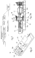
- the coiling device 10 is used to produce coils 13 of wire, round pieces or wire rods arriving directly from the rolling train.
- the coiling device 10 is placed immediately downstream of the cropping shears as shown in Fig. 1.
- the coiling device 10 comprises a rotating loop-forming head 11, of a structure substantially known, cooperating with a hollow drum 12 horizontal in development and containing the reel 13a of coiled wire.
- the loop-forming head 11 has a guide conduit 16.
- the drum 12 is mounted on a moving system 14 which moves the drum in an alternate axial manner.
- the moving system 14 enables the drum 12 to be rotated vertically, in this case by 90°, during the extraction and discharge of the completed reel 13a.
- the moving system 14 rotates the drum 12 around its longitudinal axis, in the same direction as, or the opposite direction to, the rotation of the loop-forming head 11.
- This rotary movement of the drum 12 generates contrasting radial forces able to prevent the reel 13 from slackening and/or the loops from falling, without however causing unwanted plastic deformations on the loops themselves.
- the drum 12 is taken, by the moving system 14, to a position mating with the loop-forming head 11 in such a way that the outlet mouth 11a of the head 11 is inside the drum 12, advantageously at an end position.
- the drum 12 is moved with a continuous and alternate axial movement in such a way that the outlet mouth 11a of the loop-forming head 11 is always placed in a position inside the drum 12, from one end point 12a to the other end point 12b of the working depth, or height, of the drum and vice versa.
- Each cycle of movement of the drum 12 therefore comprises a to-and-fro movement.
- the loop-forming head 11 gradually deposits a series of loops occupying the whole depth, or height, of the drum 12, the loops being distributed one on top of the other in layers along the height "h" of the drum 12.
- the loops are deposited in the opposite direction and inside the loops already deposited during the preceding step.
- the drum 12 is associated with a moving system 14 composed of two sliding elements, of which the first 14a is mounted on the second 14b.
- the two sliding elements 14a 14b move in opposite directions and at such a speed that the sum of their speeds always gives a substantially constant axial speed of the drum 12.
- the accelerations/decelerations of the first sliding element 14a during the reversals of movement are compensated for by the second sliding element 14b and vice versa, which allows the alternate axial movement of the drum 12 at a constant desired speed for the entire coiling step, the speed being correlated to the speed at which the loops leave the loop-forming head 11.
- the loops are deposited in spiral-shaped layers lying one next to the other progressively more inside on the width "l" of the coil.
- the layers of loops are deposited progressively staggered in such a way that they are arranged substantially in a petal shape.
- This distribution is obtained advantageously by arranging the loop-forming head 11 and the drum 12 inclined at a certain angle, for example between 10° and 20°, with respect to the direction of feed of the rolled product (Fig. 4), and by achieving a desired eccentricity "e" between the axis of the loop-forming head 11 and the axis of the drum 12.
- the relative speed of the loop-forming head 11 and the drum 12 is modulated during coiling in order to control the diameter of the loops produced, allowing a more compact distribution of the loops inside the drum 12 and a reduced risk of permanent deformations in the material.
- the speed of rotation of the loop-forming head 11 is progressively increased while the speed of the drum is maintained constant, in coordination with the coiling rate, from an initial value less than the speed of feed of the wire, which determines the formation of loops of an always decreasing diameter, said diameter mating with the layer which is always further inside the reel 13a of the coiled wire being formed (see Figs. 6a and 6b).
- the speed of the loop-forming head 11 is maintained substantially constant, while the speed of counter-rotation of the drum 12 is progressively increased.
- both the speed of the loop-forming head 11 and that of the drum 12 are regulated in a correlated way during the coiling step in order to obtain the desired progressive increase as the inner layers of the reel 13a of coiled wire are formed.
- the speed of the loop-forming head 11 is gradually increased at the end of every pass and thus with every formation of the outer layer of the coil in the direction of the height "h" of the coil 12.
- the speed of the loop-forming head 11 is progressively increased for every layer deposited along the width "l" of the coil, and is then cyclically slowed down again so as to form the adjacent layer.
- a station comprising two coiling devices 10 alternately fed by two pinch roll devices 15 with the product arriving from the cropping shears, can operate continuously without interruptions needed to discharge the reels 13a.
- the cropping shears can also function as a switching device to direct the wire to be coiled alternately to one or the other of the devices 10.
- the reels 13a can be removed by means of the device 17 as shown in Fig. 3b, comprising an extraction plane 21 which lifts the reel 13 outside the drum 12, and a rotary support 22 with a trolley 24 movable by jack means 23.
- the movable trolley 24 includes vertical guide means 25 on which a fork system 20 can slide, the fork system 20 being suitable to lift the reel 13a from the extraction plane 21, and means 19 for the lateral control of the coil 13.
- the device 17 is able to extract the reels 13a when they have been completed and deposit them, by means of the rotation of the rotary support 22 and the lowering of the fork system 20, onto a discharge system composed of, for example, a pinch roll device.
Landscapes
- Engineering & Computer Science (AREA)
- Mechanical Engineering (AREA)
- Winding, Rewinding, Material Storage Devices (AREA)
- Windings For Motors And Generators (AREA)
- Coiling Of Filamentary Materials In General (AREA)
Applications Claiming Priority (4)
| Application Number | Priority Date | Filing Date | Title |
|---|---|---|---|
| ITUD960111 | 1996-06-26 | ||
| ITUD960112 | 1996-06-26 | ||
| ITUD960111 IT1288934B1 (it) | 1996-06-26 | 1996-06-26 | Procedimento di bobinatura per fili metallici e relativo dispositivo |
| ITUD960112 IT1288935B1 (it) | 1996-06-26 | 1996-06-26 | Sistema di estrazione e scarico rotoli di filo metallico |
Publications (2)
| Publication Number | Publication Date |
|---|---|
| EP0815973A1 true EP0815973A1 (fr) | 1998-01-07 |
| EP0815973B1 EP0815973B1 (fr) | 2002-03-13 |
Family
ID=26332526
Family Applications (1)
| Application Number | Title | Priority Date | Filing Date |
|---|---|---|---|
| EP97109803A Expired - Lifetime EP0815973B1 (fr) | 1996-06-26 | 1997-06-17 | Procédé et dispositif d'enroulement |
Country Status (5)
| Country | Link |
|---|---|
| US (1) | US6149091A (fr) |
| EP (1) | EP0815973B1 (fr) |
| AT (1) | ATE214310T1 (fr) |
| DE (1) | DE69710955T2 (fr) |
| ES (1) | ES2174148T3 (fr) |
Cited By (3)
| Publication number | Priority date | Publication date | Assignee | Title |
|---|---|---|---|---|
| EP1477244A3 (fr) * | 2003-05-14 | 2005-01-19 | Morgan Construction Company | Méthode et dispositif pour décélérer et accumuler temporairement des produits obtenus par laminage à chaud |
| US7316145B1 (en) | 2007-02-15 | 2008-01-08 | Morgan Construction Company | Multiple outlet rolling mill |
| US8024949B2 (en) | 2008-11-17 | 2011-09-27 | Siemens Industry, Inc. | Apparatus for decelerating and temporarily accumulating hot rolled product |
Families Citing this family (7)
| Publication number | Priority date | Publication date | Assignee | Title |
|---|---|---|---|---|
| IT1310529B1 (it) * | 1999-01-26 | 2002-02-18 | Danieli Off Mecc | Testa forma spire |
| US7055244B2 (en) * | 2002-03-14 | 2006-06-06 | Anand Waman Bhagwat | Method of manufacturing flat wire coil springs to improve fatigue life and avoid blue brittleness |
| RU2224609C1 (ru) * | 2002-07-29 | 2004-02-27 | Некипелов Владимир Станиславович | Способ формирования бунта высокопрочной катанки и устройство для его осуществления |
| RU2256519C1 (ru) * | 2004-02-05 | 2005-07-20 | Некипелов Владимир Станиславович | Способ намотки тонкой ленты в рулон и устройство для его осуществления |
| US8997540B2 (en) * | 2011-09-27 | 2015-04-07 | Primetals Technologies USA LLC | Tail end ring control in a curved guide of a coiler |
| CN112105467A (zh) * | 2018-05-07 | 2020-12-18 | 鲁苏拉公司 | 线圈形成吐线机系统 |
| CN112676377B (zh) * | 2020-12-04 | 2022-11-01 | 江西同心铜业有限公司 | 一种可调节卷绕速度的铜带压延加工用卷绕机构 |
Citations (8)
| Publication number | Priority date | Publication date | Assignee | Title |
|---|---|---|---|---|
| FR994543A (fr) * | 1949-07-07 | 1951-11-19 | Construction D Installations M | Machine à bobiner du fil |
| GB759575A (en) * | 1953-08-18 | 1956-10-17 | Continental Can Co | Improvements in or relating to a method of packaging wire and a machine for carrying out the method |
| GB924409A (en) * | 1961-03-27 | 1963-04-24 | Ets Andouart Soc | Improvements in or relating to apparatus for winding coils |
| US3111286A (en) * | 1959-10-02 | 1963-11-19 | Anaconda Wire & Cable Co | Wire coiling apparatus |
| FR1425167A (fr) * | 1964-02-24 | 1966-01-14 | American Chain & Cable Co | Bobine de fil métallique |
| GB1225420A (fr) * | 1967-08-03 | 1971-03-17 | ||
| US3822045A (en) * | 1972-06-30 | 1974-07-02 | Gen Electric | Archimedes spiral wobble control |
| DE2418184A1 (de) * | 1974-04-13 | 1975-11-06 | Kocks Gmbh Friedrich | Haspelvorrichtung |
Family Cites Families (4)
| Publication number | Priority date | Publication date | Assignee | Title |
|---|---|---|---|---|
| DE2015046B2 (de) * | 1970-03-28 | 1972-05-18 | Demag Ag, 4100 Duisburg | Hebe- und uebergabevorrichtung fuer drahtbunde |
| US3675865A (en) * | 1970-11-23 | 1972-07-11 | Deering Milliken Res Corp | Apparatus for increasing the density of yarn packages |
| US3703261A (en) * | 1971-04-07 | 1972-11-21 | Southwire Co | Orbital coiler |
| DE4213459A1 (de) * | 1992-04-24 | 1993-10-28 | Schloemann Siemag Ag | Vorrichtung zum Transport von zu Ringen gewickeltem Walzgut im Haspelbereich |
-
1997
- 1997-06-17 ES ES97109803T patent/ES2174148T3/es not_active Expired - Lifetime
- 1997-06-17 EP EP97109803A patent/EP0815973B1/fr not_active Expired - Lifetime
- 1997-06-17 AT AT97109803T patent/ATE214310T1/de not_active IP Right Cessation
- 1997-06-17 DE DE69710955T patent/DE69710955T2/de not_active Expired - Fee Related
- 1997-06-25 US US08/882,494 patent/US6149091A/en not_active Expired - Fee Related
Patent Citations (8)
| Publication number | Priority date | Publication date | Assignee | Title |
|---|---|---|---|---|
| FR994543A (fr) * | 1949-07-07 | 1951-11-19 | Construction D Installations M | Machine à bobiner du fil |
| GB759575A (en) * | 1953-08-18 | 1956-10-17 | Continental Can Co | Improvements in or relating to a method of packaging wire and a machine for carrying out the method |
| US3111286A (en) * | 1959-10-02 | 1963-11-19 | Anaconda Wire & Cable Co | Wire coiling apparatus |
| GB924409A (en) * | 1961-03-27 | 1963-04-24 | Ets Andouart Soc | Improvements in or relating to apparatus for winding coils |
| FR1425167A (fr) * | 1964-02-24 | 1966-01-14 | American Chain & Cable Co | Bobine de fil métallique |
| GB1225420A (fr) * | 1967-08-03 | 1971-03-17 | ||
| US3822045A (en) * | 1972-06-30 | 1974-07-02 | Gen Electric | Archimedes spiral wobble control |
| DE2418184A1 (de) * | 1974-04-13 | 1975-11-06 | Kocks Gmbh Friedrich | Haspelvorrichtung |
Cited By (4)
| Publication number | Priority date | Publication date | Assignee | Title |
|---|---|---|---|---|
| EP1477244A3 (fr) * | 2003-05-14 | 2005-01-19 | Morgan Construction Company | Méthode et dispositif pour décélérer et accumuler temporairement des produits obtenus par laminage à chaud |
| US7021103B2 (en) | 2003-05-14 | 2006-04-04 | Morgan Construction Company | Method and apparatus for decelerating and temporarily accumulating a hot rolled product |
| US7316145B1 (en) | 2007-02-15 | 2008-01-08 | Morgan Construction Company | Multiple outlet rolling mill |
| US8024949B2 (en) | 2008-11-17 | 2011-09-27 | Siemens Industry, Inc. | Apparatus for decelerating and temporarily accumulating hot rolled product |
Also Published As
| Publication number | Publication date |
|---|---|
| EP0815973B1 (fr) | 2002-03-13 |
| ES2174148T3 (es) | 2002-11-01 |
| DE69710955D1 (de) | 2002-04-18 |
| DE69710955T2 (de) | 2004-01-29 |
| ATE214310T1 (de) | 2002-03-15 |
| US6149091A (en) | 2000-11-21 |
Similar Documents
| Publication | Publication Date | Title |
|---|---|---|
| EP0815973B1 (fr) | Procédé et dispositif d'enroulement | |
| EP1126934B1 (fr) | Machine de bobinage pour materiau lamine | |
| CA1115671A (fr) | Systeme de boudinage de torons metalliques | |
| US5343934A (en) | Multiple pinch roll apparatus and method for advancing a continuous rod | |
| US6915978B2 (en) | Method of rod coil forming and set of equipment for its realization | |
| EP0200432B1 (fr) | Tuyau métallique flexible enclenché | |
| US5293927A (en) | Method and apparatus for making strips, bars and wire rods | |
| KR100572643B1 (ko) | 열간 압연 생산품을 감속 및 임시 축적하기 위한 방법 및장치 | |
| KR0137868B1 (ko) | 고속코일링장치 | |
| EP0686438B1 (fr) | Dispositif pour déposer asymétriquement des boucles | |
| KR101008136B1 (ko) | 선재 권취 가이드장치 | |
| EP1126935B1 (fr) | Dispositif spiraleur pour bobineuse de produits demi-finis lamines | |
| EP0979689B1 (fr) | Dispositif pour minimiser la hauteur de bobines de fil dans un tambour de réformation de spires de fil | |
| KR20200138781A (ko) | 열간 압연 제품의 코일 권선 방법 및 시스템 | |
| EP1706223B1 (fr) | Dispositif et methode de bobinage de produits longs lamines ou etires | |
| RU2110385C1 (ru) | Линия для производства порошковой проволоки в металлической оболочке | |
| KR101008151B1 (ko) | 선재코일 집적기의 코일 정리장치 | |
| CN216730174U (zh) | 一种自动化药芯焊丝生产线 | |
| US3872702A (en) | Coiling elongated materials | |
| US3481172A (en) | Wire-bending machine | |
| AU2004240904B2 (en) | Method and apparatus for decelerating and temporarily accumulating a hot rolled product | |
| BE719957A (fr) | ||
| ITUD960111A1 (it) | Procedimento di bobinatura per fili metallici e relativo dispositivo | |
| SA04250205A (ar) | طريقة وجهاز لابطاء السرعة والرص المؤقت لمنتج مدرفل على الساخن |
Legal Events
| Date | Code | Title | Description |
|---|---|---|---|
| PUAI | Public reference made under article 153(3) epc to a published international application that has entered the european phase |
Free format text: ORIGINAL CODE: 0009012 |
|
| AK | Designated contracting states |
Kind code of ref document: A1 Designated state(s): AT BE DE ES FR GB IT SE |
|
| 17P | Request for examination filed |
Effective date: 19980630 |
|
| AKX | Designation fees paid |
Free format text: AT BE DE ES FR GB IT SE |
|
| RBV | Designated contracting states (corrected) |
Designated state(s): AT BE DE ES FR GB IT SE |
|
| 17Q | First examination report despatched |
Effective date: 20000221 |
|
| GRAG | Despatch of communication of intention to grant |
Free format text: ORIGINAL CODE: EPIDOS AGRA |
|
| GRAG | Despatch of communication of intention to grant |
Free format text: ORIGINAL CODE: EPIDOS AGRA |
|
| GRAG | Despatch of communication of intention to grant |
Free format text: ORIGINAL CODE: EPIDOS AGRA |
|
| GRAH | Despatch of communication of intention to grant a patent |
Free format text: ORIGINAL CODE: EPIDOS IGRA |
|
| GRAH | Despatch of communication of intention to grant a patent |
Free format text: ORIGINAL CODE: EPIDOS IGRA |
|
| REG | Reference to a national code |
Ref country code: GB Ref legal event code: IF02 |
|
| GRAA | (expected) grant |
Free format text: ORIGINAL CODE: 0009210 |
|
| RAP1 | Party data changed (applicant data changed or rights of an application transferred) |
Owner name: DANIELI & C. OFFICINE MECCANICHE SPA |
|
| AK | Designated contracting states |
Kind code of ref document: B1 Designated state(s): AT BE CH DE ES FI FR GB GR IT LI NL SE |
|
| PG25 | Lapsed in a contracting state [announced via postgrant information from national office to epo] |
Ref country code: NL Free format text: LAPSE BECAUSE OF FAILURE TO SUBMIT A TRANSLATION OF THE DESCRIPTION OR TO PAY THE FEE WITHIN THE PRESCRIBED TIME-LIMIT Effective date: 20020313 Ref country code: LI Free format text: LAPSE BECAUSE OF FAILURE TO SUBMIT A TRANSLATION OF THE DESCRIPTION OR TO PAY THE FEE WITHIN THE PRESCRIBED TIME-LIMIT Effective date: 20020313 Ref country code: GR Free format text: LAPSE BECAUSE OF FAILURE TO SUBMIT A TRANSLATION OF THE DESCRIPTION OR TO PAY THE FEE WITHIN THE PRESCRIBED TIME-LIMIT Effective date: 20020313 Ref country code: FI Free format text: LAPSE BECAUSE OF FAILURE TO SUBMIT A TRANSLATION OF THE DESCRIPTION OR TO PAY THE FEE WITHIN THE PRESCRIBED TIME-LIMIT Effective date: 20020313 Ref country code: CH Free format text: LAPSE BECAUSE OF FAILURE TO SUBMIT A TRANSLATION OF THE DESCRIPTION OR TO PAY THE FEE WITHIN THE PRESCRIBED TIME-LIMIT Effective date: 20020313 Ref country code: BE Free format text: LAPSE BECAUSE OF FAILURE TO SUBMIT A TRANSLATION OF THE DESCRIPTION OR TO PAY THE FEE WITHIN THE PRESCRIBED TIME-LIMIT Effective date: 20020313 |
|
| REF | Corresponds to: |
Ref document number: 214310 Country of ref document: AT Date of ref document: 20020315 Kind code of ref document: T |
|
| REG | Reference to a national code |
Ref country code: CH Ref legal event code: EP |
|
| REF | Corresponds to: |
Ref document number: 69710955 Country of ref document: DE Date of ref document: 20020418 |
|
| ET | Fr: translation filed | ||
| PG25 | Lapsed in a contracting state [announced via postgrant information from national office to epo] |
Ref country code: SE Free format text: LAPSE BECAUSE OF FAILURE TO SUBMIT A TRANSLATION OF THE DESCRIPTION OR TO PAY THE FEE WITHIN THE PRESCRIBED TIME-LIMIT Effective date: 20020613 |
|
| NLV1 | Nl: lapsed or annulled due to failure to fulfill the requirements of art. 29p and 29m of the patents act | ||
| REG | Reference to a national code |
Ref country code: CH Ref legal event code: PL |
|
| REG | Reference to a national code |
Ref country code: ES Ref legal event code: FG2A Ref document number: 2174148 Country of ref document: ES Kind code of ref document: T3 |
|
| PLBE | No opposition filed within time limit |
Free format text: ORIGINAL CODE: 0009261 |
|
| STAA | Information on the status of an ep patent application or granted ep patent |
Free format text: STATUS: NO OPPOSITION FILED WITHIN TIME LIMIT |
|
| 26N | No opposition filed |
Effective date: 20021216 |
|
| PGFP | Annual fee paid to national office [announced via postgrant information from national office to epo] |
Ref country code: ES Payment date: 20080606 Year of fee payment: 12 |
|
| PGFP | Annual fee paid to national office [announced via postgrant information from national office to epo] |
Ref country code: AT Payment date: 20080526 Year of fee payment: 12 |
|
| PGFP | Annual fee paid to national office [announced via postgrant information from national office to epo] |
Ref country code: IT Payment date: 20080614 Year of fee payment: 12 |
|
| PGFP | Annual fee paid to national office [announced via postgrant information from national office to epo] |
Ref country code: DE Payment date: 20080617 Year of fee payment: 12 |
|
| PGFP | Annual fee paid to national office [announced via postgrant information from national office to epo] |
Ref country code: FR Payment date: 20080630 Year of fee payment: 12 |
|
| PGFP | Annual fee paid to national office [announced via postgrant information from national office to epo] |
Ref country code: GB Payment date: 20080527 Year of fee payment: 12 |
|
| GBPC | Gb: european patent ceased through non-payment of renewal fee |
Effective date: 20090617 |
|
| REG | Reference to a national code |
Ref country code: FR Ref legal event code: ST Effective date: 20100226 |
|
| PG25 | Lapsed in a contracting state [announced via postgrant information from national office to epo] |
Ref country code: FR Free format text: LAPSE BECAUSE OF NON-PAYMENT OF DUE FEES Effective date: 20090630 |
|
| PG25 | Lapsed in a contracting state [announced via postgrant information from national office to epo] |
Ref country code: GB Free format text: LAPSE BECAUSE OF NON-PAYMENT OF DUE FEES Effective date: 20090617 |
|
| PG25 | Lapsed in a contracting state [announced via postgrant information from national office to epo] |
Ref country code: DE Free format text: LAPSE BECAUSE OF NON-PAYMENT OF DUE FEES Effective date: 20100101 Ref country code: AT Free format text: LAPSE BECAUSE OF NON-PAYMENT OF DUE FEES Effective date: 20090617 |
|
| REG | Reference to a national code |
Ref country code: ES Ref legal event code: FD2A Effective date: 20090618 |
|
| PG25 | Lapsed in a contracting state [announced via postgrant information from national office to epo] |
Ref country code: ES Free format text: LAPSE BECAUSE OF NON-PAYMENT OF DUE FEES Effective date: 20090618 |
|
| PG25 | Lapsed in a contracting state [announced via postgrant information from national office to epo] |
Ref country code: IT Free format text: LAPSE BECAUSE OF NON-PAYMENT OF DUE FEES Effective date: 20090617 |