EP0816091B1 - Procédé de commande d'une tête d'enregistement comportant plusieurs éléments chauffants par buse - Google Patents
Procédé de commande d'une tête d'enregistement comportant plusieurs éléments chauffants par buse Download PDFInfo
- Publication number
- EP0816091B1 EP0816091B1 EP97304658A EP97304658A EP0816091B1 EP 0816091 B1 EP0816091 B1 EP 0816091B1 EP 97304658 A EP97304658 A EP 97304658A EP 97304658 A EP97304658 A EP 97304658A EP 0816091 B1 EP0816091 B1 EP 0816091B1
- Authority
- EP
- European Patent Office
- Prior art keywords
- electro
- ink
- thermal transducer
- transducer element
- discharge
- Prior art date
- Legal status (The legal status is an assumption and is not a legal conclusion. Google has not performed a legal analysis and makes no representation as to the accuracy of the status listed.)
- Expired - Lifetime
Links
Images


Classifications
-
- B—PERFORMING OPERATIONS; TRANSPORTING
- B41—PRINTING; LINING MACHINES; TYPEWRITERS; STAMPS
- B41J—TYPEWRITERS; SELECTIVE PRINTING MECHANISMS, i.e. MECHANISMS PRINTING OTHERWISE THAN FROM A FORME; CORRECTION OF TYPOGRAPHICAL ERRORS
- B41J2/00—Typewriters or selective printing mechanisms characterised by the printing or marking process for which they are designed
- B41J2/005—Typewriters or selective printing mechanisms characterised by the printing or marking process for which they are designed characterised by bringing liquid or particles selectively into contact with a printing material
- B41J2/01—Ink jet
- B41J2/015—Ink jet characterised by the jet generation process
- B41J2/04—Ink jet characterised by the jet generation process generating single droplets or particles on demand
- B41J2/045—Ink jet characterised by the jet generation process generating single droplets or particles on demand by pressure, e.g. electromechanical transducers
- B41J2/04501—Control methods or devices therefor, e.g. driver circuits, control circuits
- B41J2/04563—Control methods or devices therefor, e.g. driver circuits, control circuits detecting head temperature; Ink temperature
-
- B—PERFORMING OPERATIONS; TRANSPORTING
- B41—PRINTING; LINING MACHINES; TYPEWRITERS; STAMPS
- B41J—TYPEWRITERS; SELECTIVE PRINTING MECHANISMS, i.e. MECHANISMS PRINTING OTHERWISE THAN FROM A FORME; CORRECTION OF TYPOGRAPHICAL ERRORS
- B41J2/00—Typewriters or selective printing mechanisms characterised by the printing or marking process for which they are designed
- B41J2/005—Typewriters or selective printing mechanisms characterised by the printing or marking process for which they are designed characterised by bringing liquid or particles selectively into contact with a printing material
- B41J2/01—Ink jet
- B41J2/015—Ink jet characterised by the jet generation process
- B41J2/04—Ink jet characterised by the jet generation process generating single droplets or particles on demand
- B41J2/045—Ink jet characterised by the jet generation process generating single droplets or particles on demand by pressure, e.g. electromechanical transducers
- B41J2/04501—Control methods or devices therefor, e.g. driver circuits, control circuits
- B41J2/0458—Control methods or devices therefor, e.g. driver circuits, control circuits controlling heads based on heating elements forming bubbles
-
- B—PERFORMING OPERATIONS; TRANSPORTING
- B41—PRINTING; LINING MACHINES; TYPEWRITERS; STAMPS
- B41J—TYPEWRITERS; SELECTIVE PRINTING MECHANISMS, i.e. MECHANISMS PRINTING OTHERWISE THAN FROM A FORME; CORRECTION OF TYPOGRAPHICAL ERRORS
- B41J2/00—Typewriters or selective printing mechanisms characterised by the printing or marking process for which they are designed
- B41J2/005—Typewriters or selective printing mechanisms characterised by the printing or marking process for which they are designed characterised by bringing liquid or particles selectively into contact with a printing material
- B41J2/01—Ink jet
- B41J2/015—Ink jet characterised by the jet generation process
- B41J2/04—Ink jet characterised by the jet generation process generating single droplets or particles on demand
- B41J2/045—Ink jet characterised by the jet generation process generating single droplets or particles on demand by pressure, e.g. electromechanical transducers
- B41J2/04501—Control methods or devices therefor, e.g. driver circuits, control circuits
- B41J2/04591—Width of the driving signal being adjusted
-
- B—PERFORMING OPERATIONS; TRANSPORTING
- B41—PRINTING; LINING MACHINES; TYPEWRITERS; STAMPS
- B41J—TYPEWRITERS; SELECTIVE PRINTING MECHANISMS, i.e. MECHANISMS PRINTING OTHERWISE THAN FROM A FORME; CORRECTION OF TYPOGRAPHICAL ERRORS
- B41J2/00—Typewriters or selective printing mechanisms characterised by the printing or marking process for which they are designed
- B41J2/005—Typewriters or selective printing mechanisms characterised by the printing or marking process for which they are designed characterised by bringing liquid or particles selectively into contact with a printing material
- B41J2/01—Ink jet
- B41J2/135—Nozzles
- B41J2/14—Structure thereof only for on-demand ink jet heads
- B41J2/14016—Structure of bubble jet print heads
- B41J2/14032—Structure of the pressure chamber
- B41J2/14056—Plural heating elements per ink chamber
-
- B—PERFORMING OPERATIONS; TRANSPORTING
- B41—PRINTING; LINING MACHINES; TYPEWRITERS; STAMPS
- B41J—TYPEWRITERS; SELECTIVE PRINTING MECHANISMS, i.e. MECHANISMS PRINTING OTHERWISE THAN FROM A FORME; CORRECTION OF TYPOGRAPHICAL ERRORS
- B41J2/00—Typewriters or selective printing mechanisms characterised by the printing or marking process for which they are designed
- B41J2/005—Typewriters or selective printing mechanisms characterised by the printing or marking process for which they are designed characterised by bringing liquid or particles selectively into contact with a printing material
- B41J2/01—Ink jet
- B41J2/135—Nozzles
- B41J2/14—Structure thereof only for on-demand ink jet heads
- B41J2/14016—Structure of bubble jet print heads
- B41J2/14072—Electrical connections, e.g. details on electrodes, connecting the chip to the outside...
Definitions
- the present invention relates to an ink discharging method using an ink jet head for discharging ink toward a medium (sheet, cap, etc.) by an input of an electrical signal, and an ink jet recording apparatus for implementing the ink discharging method and an ink jet recording head to be mounted on the apparatus. More particularly, the present invention relates to the drive of a recording head having a plurality of heaters arranged in each nozzle.
- the ink jet recording apparatus have been known as printing apparatus in such equipments as printers, facsimile machines, word processors and copying machines.
- the ink jet recording apparatus of a system using thermal energy as energy to be utilized for the ink discharge that is, a system which generates bubbles in ink by the thermal energy and discharges the ink by using a pressure in generating the bubbles has recently been widely used.
- an ink jet dying apparatus which prints a predetermined pattern or picture or a synthesized image on cloth has recently been developed.
- the ink jet recording head used in the above ink jet recording apparatus uses electro-thermal transducer elements (hereinafter also referred to as heaters) to generate the thermal energy.
- the heaters are normally arranged in an ink flow path (hereinafter also referred to as a nozzle) connected to an orifice.
- a nozzle ink flow path
- such an ink jet recording head adopts an arrangement of providing one heater for one nozzle.
- a distance from a center of gravity of the heater to the orifice (hereinafter referred to as OH) is a significant factor which influences a discharge characteristic of the ink jet recording head such as a discharge rate of ink droplets and a refill frequency.
- a discharge characteristic of the ink jet recording head such as a discharge rate of ink droplets and a refill frequency.
- the discharge rate is higher as the OH is shorter, and for the refill frequency, the frequency is lower as the OH is shorter.
- the print dots must be increased because the one-dot area displayed by the small ink droplet is reduced, and a higher print speed than that in the prior art, particularly the improvement of the refill frequency is required.
- the refill frequency is lowered as the OH is reduced, the print speed is lower than that of the prior art when the above method is used.
- the predischarge which is conducted as a part of the discharge recovery process.
- the ink which does not serve to the recording is discharged from the ink jet recording head at a predetermined position in the apparatus. In this manner, the high viscosity ink in the ink jet recording head is removed to keep good ink discharge condition.
- Such predischarge is normally conducted immediately after the power-on of the apparatus and periodically during the printing.
- the printing is conducted by the small ink droplets or in the low temperature/low humidity environment, it is necessary to reduce the interval between predischarges. Because the discharge power by the small ink droplets is low and the high viscosity ink may not be stably discharged depending on the condition of the viscosity of the ink due to the evaporation of water at the orifice.
- the predischarge is conducted at the predetermined non-print unit, it takes a long time. Accordingly, even if the discharge frequency is raised, the substantial print time may be long. Further, the consumption of the ink by the frequently conducted predischarge is not negligible.
- Fig. 8 shows a relation between the distance OH and the predischarge interval IPE together with the discharge characteristic described above.
- the predischarge interval may be remarkably long.
- the pre-discharge interval and the refill frequency fr of the ink are of conflict relation.
- an apparatus having a plurality of heaters for each orifice from the viewpoint described below has been known. It uses a plurality of heaters for the purpose of increasing a range in which the ink discharge amount is changed. In this case, the discharge amount is changed by selecting the heaters to be driven (that is, the heaters to generate heat) and the number thereof.
- a plurality of heaters are arranged along the direction of ink discharge in the liquid flow path connected to the orifice of the ink jet head, and the distance between the orifice and the center of the driven heater is changed by selecting the driven heaters and the number thereof so that the discharge amount is changed.
- a plurality of heaters having different surface areas from each other are arranged in the liquid flow path, and the driven heaters or the number thereof is changed to change the ink discharge amount.
- Patent Abstracts of Japan, Volume 011, No. 221 (M-608), 17 July 1987 discloses a recording apparatus using thermo-electric elements to generate bubbles that eject ink droplets.
- the disclosed arrangement uses a pair of heaters in each nozzle. Either the downstream heater is used on its own to eject small ink drops, or both the upstream and the downstream heaters are used in tandem to eject large ink drops.
- Patent Abstracts of Japan, Volume 012, No. 141 (M-691), 28 April 1988 discloses an ink jet head having heaters of different sizes that are operable to discharge differing amounts of ink in proportion to the heater area.
- the heaters may be used singly or in combination to increase the variety of ink droplet sizes that are obtainable.
- Patent Abstracts of Japan, Volume 004, No. 187 (M-048), 23 December 1980, discloses a liquid jet recording method that uses a plurality of heating elements in the discharge orifice. Different timings are used to activate respective heaters for generating different ink amounts. The variable droplet size is for achieving gradation in the recorded image.
- United States Patent No. 5,172,139 discloses a liquid jet head of the side shooter type for gradation recording.
- a plurality of heaters in the liquid discharge path may be deployed singly or in combination to vary the size of the ejected ink droplet, thereby achieving gradation on the recording medium.
- United States Patent No. 5,479,196 is concerned with the recovery of a normal ink discharge condition, i.e. free from clogging, in an ink jet recording apparatus.
- a purging operation is effected using a heater element or elements that generate a bubble or void which completely forces ink out of the ink passage. Refilling after purging is akin to the initial filling procedure.
- European Patent Application No. 0 747 221 which forms part of the state of the art by virtue of Article 54(3)EPC, discloses an ink jet head comprising ink flow paths each having a plurality of heat generating resistors for generating bubbles that contribute to ink ejection.
- the heaters in each ink path are disposed in parallel such that their centers are separated from the ink ejection outlet by different amounts.
- the ink of small discharge amount when the ink of small discharge amount is discharged, bubbles are generated by heaters having a small discharge power, that is, having a small heater area. As a result, not only the discharge amount but also the discharge rate are reduced. As an important matter, a problem may occur in connection with the predischarge which is conducted as a part of the discharge recovery process.
- the predischarge the ink which does not serve to the printing is discharged from the ink jet head at a predetermined position in the apparatus. Thus, the high viscosity ink in the ink jet head is removed and a good ink discharge condition may be maintained.
- the predischarge is normally conducted immediately after the power-on of the apparatus and periodically during the printing.
- the printing is made at the small discharge amount getting, it is necessary to shorten the predischarge interval. If the interval is too long, the high viscosity ink may not be stably discharged depending on the condition of the viscosity of the ink due to the evaporation of the water at the orifice because the power of the small discharge ink droplets is low. As a result, it is necessary to shorten the predischarge interval periodically conducted during the printing and the throughput of the printing is lowered.
- the present invention provides an ink discharge method comprising the steps of:
- the present invention provides an ink jet recording head including:
- the present invention provides an ink jet recording apparatus (IJRA) having an ink jet recording head (IJC) as described above.
- Embodiments of the present invention provide an improvement in refill frequency over the prior art by reducing the discharge rate of the ink droplets in the ink jet recording head.
- Embodiments of the present invention provide an ink jet recording head and an ink jet recording apparatus which allow the discharge (recording) with variable discharge amount with a relatively simple construction and at an optimum discharge condition for the purpose of the head usage and the head use condition.
- the present invention fully utilizes the discharge characteristic in which, by switching the electro-thermal transducer element to be driven, the discharge rate increases as the position of the electro-thermal transducer element is closer to the orifice and the refill frequency, contrary to the discharge rate, decreases as the position of the electro-thermal transducer element is closer to the orifice.
- the present invention has been made from the novel features resulted from the discussion of the practical use as the recording apparatus in the head structure to be described hereinlater.
- Fig. 1 shows a perspective view of the ink jet recording head.
- the recording head is of a type called an edge shooter type and a nozzle arrangement density is 360 DPI.
- an element board 23 having a plurality of heaters which are electro-thermal transducer elements arranged is arranged on a support 41 formed by a metal such as aluminum.
- Orifices 40 which are discharge ports for discharging ink and nozzle walls 5 are provided on a top plate 101. As shown, the element board 23 and the top plate 101 are joined to form nozzles 104 and ink chambers 105.
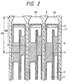
- Fig. 2 shows a diagram of an arrangement of the heaters on the element board of the ink jet recording head.
- a front heater 3 and a rear heater 4 are arranged partially side by side and with different distances OH from a center of gravity of the heater to the discharge port (orifice).
- the respective heaters 3 and 4 are connected to a common wiring 1 under interlayer insulation films of under layers of the heaters 3 and 4 through through-holes 2 and a voltage is applied by the common wiring 1.
- Wirings 6 and 7 are connected to the front heater 3 and the rear heater 4, respectively.
- Inks are supplied from the ink chambers 105 to the nozzles 104, the heaters 3 and 4 provided in the nozzles 104 are driven by signal currents to heat the inks in the nozzles to cause the generation of bubbles, and the inks in the nozzles are discharged toward a recording medium by the generation of the bubbles.
- the two heaters 3 and 4 of substantially the same size and same length are arranged in the nozzle 104 and the discharge amounts of the small droplets when the two heaters are independently driven, are substantially the same, approximately 20 pl.
- the distance OH between the center of gravity of the heater and the discharge port (orifice) is a significant factor to influence the discharge characteristics.
- the distance OH is used as a parameter, it has been proven by study that the discharge amount Vd (pl) of the droplets, the discharge rate v (m/s) and the refill frequency fr (Khz) exhibit the following characteristics.
- the refill frequency fr is significantly improved when the rear heater 4 which is farther from the orifice (longer OH) is driven as shown in Fig. 5.
- the refill frequency fr is higher because a return time of a meniscus is faster.
- the discharge rate v is low as shown in Fig. 4.
- the discharge rate v is significantly improved, but, on the other hand, the refill frequency fr is low as shown in Fig. 5.
- the discharge rate v and the refill frequency fr are of conflict relation.
- the discharge amount Vd is substantially constant for the distance OH and any OH may be selected.
- the discharge amounts when the respective heaters are independently driven may be made substantially equal.
- the distances OH may be set to B1 and A1 shown in Fig. 3 and the size of the front heater 3 may be made larger than the size of the rear heater 4. In this case, it has been proved that the discharge characteristics described above do not basically change.
- Fig. 6 shows a chart of relations between the discharge amount Vd of the droplets and the discharge rate v, and between a product of a discharge port area So and the distance OH from the discharge port to the end of the heater and the distance OH
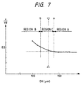
- Fig. 7 shows a relation between a quotient (v/Vd) of the discharge rate v divided by the discharge amount Vd and the distance OH.
- peculiar points a and b are defined and the distance OH is divided into three areas, an area A not smaller than a, an area B not larger than b and an area C between a and b.
- the discharge rate v and the discharge amount Vd are substantially proportional, and v/Vd is substantially constant. It is also pointed out that, in the area B, the discharge amount Vd is substantially proportional to the product of the discharge area So and the distance OH, and in the area C, the discharge amount is substantially constant.
- the areas A to C may be defined as follows when they are viewed from the discharge amount Vd and the discharge rate v, respectively.
- the discharge amount Vd is substantially constant for the distance OH.
- the discharge amount Vd of the ink droplets exhibits a peak at a predetermined distance OH and decreases as it departs from the predetermined distance OH.
- the discharge amounts Vd of the rear heater 4 and the front heater 3 may be made substantially equal by arranging the rear heater 4 in the area A and the front heater 3 in the area B so that the distances OH of the respective heaters are symmetric about the distance OH which is a flection point.
- the front heater 3 and the rear heater 4 are alternately driven such that the front heater 3 is first driven to discharge the ink droplets, then the rear heater 4 is driven to discharge the ink droplets, and then the front heater 3 is driven.
- the refill frequency may be improved without lowering the discharge rate.
- the front heater 3 is driven to discharge the ink droplets by the pressure of bubbles of the ink generated on the heater surface.
- the front flow resistance of the bubbles in this case the inertance in front of the center of gravity of the heater
- the discharge rate v of the ink droplets is high.
- the bubbles generated on the heater surface shrink and the meniscus at the orifice is pulled in.
- the distance of the front heater 3 is closer to the orifice, the time required for the meniscus to return before the discharge is short. In other words, the refill frequency is low.
- the nozzle drive frequency is 12 kHz and when the ink is to be continuously discharged from the nozzle, the meniscus frequency fr is approximately 9 kHz at most and the meniscus may not fully return.
- the ink amount in front of the heater reduces and the droplets with small discharge amount Vd are discharged.
- the discharge power of the heater increases and the printing become blurred if the solid printing is conducted, and the image quality is lowered.
- the discharge amount and the discharge rate are substantially equal to those when the front heater is driven by the action to be described later.
- the discharge amount Vd does not significantly change from that when the front heater 3 is driven as described above, but the reduction rate of the discharge rate v is large.
- the discharge rate v is high by the effect that the distance between the meniscus and the heater is shorter. Since the flat portion of the meniscus to which the impact of the bubbles acts is narrow, the same effect as that of the reduction of the orifice diameter is attained and it is considered that this contributes to the increase of the discharge rate v. Further, since the distance to the orifice in front of the heater increases, the discharge amount Vd is not reduced and the stable discharge is attained.
- the bubbles generated on the rear heater surface shrink and the meniscus of the orifice is pulled in.
- the refill time that is, the time required for the meniscus to return to the condition before the discharge is short. In other words, the refill frequency fr rises.
- the predischarge interval may be set longer.
- the first embodiment relates to the continuous discharge of the small ink droplets.
- the front and rear heaters of the ink jet recording head of the Embodiment 1 are simultaneously driven to attain the discharge of the ink droplets at approximately double amount or approximately 40 pl to attain half tone presentation.
- the present embodiment illustrates the half tone presentation by the ink jet recording head of the present invention.
- the ink jet recording head of the present embodiment has two modes, a large ink droplet discharge mode for discharging large ink droplets and a small ink droplet discharge mode for discharging small ink droplets.
- a drive method when the printing is made with the large dot mode printing for discharging the large ink droplets and the small dot mode printing for discharging the small ink droplets mixed, is explained below.
- Figs. 9A and 9B show data processings when the printing is made with the large dots and the small dots mixed.
- Fig. 9A discharge data
- Fig. 9B shows the heater driven by the image data of Fig. 9A.
- FIGs. 9A and 9B F represents the drive of only the front heater, B represents the drive of only the rear heater and F+B represents the drive of the front and rear heaters.
- the small dots are represented by small dots 51 and the large dots are represented by large dots 52.
- Figs. 9A and 9B show the manner in which the ink droplets are discharged from left to right in the drawings.
- the heater to be driven (F, B or F+B) is determined for each nozzle by the data processing and the basic matters of the manner of determination are described below.
- the excellent discharge rate and refill frequency are secured even when the half tone presentation is conducted, and the half tone presentation of high grade is attained.
- the heater to be driven may be driven by drive control means of the ink jet recording apparatus or drive switching means may be provided in the ink jet recording head.
- the refill frequency may be significantly improved without lowering the discharge rate of the ink droplets and the predischarge interval may also be increased.
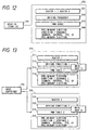
- Fig. 10 shows a block diagram of a third embodiment of the ink jet recording apparatus of the present invention.
- the heater to be driven is switched in accordance with temperature environment information of a main unit.
- the apparatus comprises discharge amount setting means 100, print mode setting means 101 and detection means (temperature sensor) 102 for the temperature in the main unit, and it follows a selected desired mode and control means 200 switches the heater to be driven in accordance with the temperature in the main unit and the discharge is made at the condition appropriate to the switched heaters.
- the control means 200 comprises means 201 for controlling the switching of the heaters, means 202 for controlling the drive frequency, a table 203 for modulating a pulse width, means 204 for controlling the predischarge condition and means 205 for controlling the discharge timing.
- the discharge amount control is first explained.
- the discharge amount mode basically includes two modes, a small discharge amount mode and a large discharge amount mode.
- the main heater to driven is switched in accordance with the discharge amount mode.
- the small discharge amount mode comprises a first small discharge amount mode for driving only the rear heater and a second small discharge amount mode for driving only the front heater to discharge the same amount of ink droplets as that in the first small amount mode.
- the large discharge amount mode drives both the front heater and the rear heater.
- the print mode may comprise a basic density print mode at 360 dpi, a high density print mode at 720 dpi, a smoothing mode for smoothing the outline of the printing and a multi-value record mode.
- the printing at 360 dpi is made in the large discharge amount mode by using all nozzles.
- the printing at 720x720 dpi is made by the interlace printing in the sub-scan direction, that is, the printing for filling the space between print dots in the feed direction of the recording medium transverse to the scan direction of the head, basically in the small discharge amount mode by using all nozzles.
- the smoothing mode the roughness of the outline of the printing is smoothed by using the smaller discharge amount (small discharge amount mode) than that in the basic density print mode at 360 dpi for the outline of the printing by the basic density print mode.
- the large dot by the large discharge amount mode and the small dot by the small discharge amount mode are switched for each pixel.
- the three-value (non-dot, large dot, small dot) half tone presentation may be effectively attained for each pixel by using a spread-free sheet.
- the high speed printing at the drive frequency of 12 KHz which is approximately double of the basic density printing may be attained by using the rear heater.
- This operation mode is called a "high speed print mode".
- the discharge amount in this mode is set to 35 pl for the black ink and 20 pl for the color ink.
- the head scan speed is same as that of the basic density print mode at 360 dpi.
- the printing is made at the drive frequency of 8 KHz which is slightly lower than that of the high speed print mode by driving the front heater, and the printing of higher discharge rate, that is, higher discharge power than those of the high speed print mode is attained.
- This operation mode is called a "discharge reliability priority mode".
- the discharge amount in this mode is same as that in the first small discharge amount mode and set to 35 pl for the black ink and 20 pl for the color ink.
- the head scan speed is set to 2/3 of that in the high speed print mode.
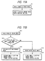
- the switching of the "high speed print mode” and the “discharge reliability priority mode” in the high density print mode is conducted by the temperature environment of the head monitored by the detection means (temperature sensor) (see Fig. 11B, S11 to S16).
- the printing is made in the "high speed print mode".
- the rear heater is driven in the high speed print mode, it is necessary to set the predischarge interval to be substantially short when the head is in the low temperature/low humidity environment by the affect of the increase of the viscosity of the ink as seen from the graph shown in Fig. 8.
- the predischarge takes a long time because it is made in the predetermined non-print unit. Accordingly, even if the discharge drive frequency is raised in the high speed print mode, the substantial print time is long because the predischarge interval must be set substantially short. Further, when the predischarge is frequently conducted, the consumption of the ink is large.
- the mode is switched to the "discharge reliability priority mode" to prevent the failure of the discharge due to the increase of the viscosity of the ink at the orifice so that the printing is made by the front heater having the higher discharge power.
- the head discharge drive frequency is set to 8 KHz which is slightly lower than that in the high speed print mode and the predischarge interval is set long as seen from the graph of Fig. 8 so that the time required for the predischarge may be shortened. As a result, the substantial print speed is increased Further, the consumption of the ink is reduced.
- the discharge amount mode When the discharge amount mode is switched for one mode as described above, the ink droplets of different discharge amounts are discharged from the same nozzle and the discharge rate changes between the large discharge amount mode and the small discharge amount mode.
- the smoothing mode or the multi-value record mode is selected, the large dots and the small dots are mixedly discharged during the forward scan of the head and it may be considered that the precision of the impact point is deteriorated by the difference of the discharge rates of the large and small dots.
- the impact points of the large and small dots are aligned to the center position by changing the discharge timings of the ink droplets in accordance with the discharge amount mode.
- the discharge timing of the large dot is delayed. Even for the small dot, when the front heater is driven (second small discharge amount mode), since the discharge rate of the small dot may be high and the difference from the discharge rate of the large dot is small, the discharge timing may not be changed. In this manner, even in the smoothing mode or the multi-value record mode in which the large and small dots are mixedly discharged during the forward scan of the head, a high precision image is attained by changing the discharge timing in accordance with the switching of the heater.
- a high precision image may be attained by discharging the large dots in the forward scan of the printing and the small dots in the backward scan.
- the so-called pre-heat PWM control is usually conducted by double pulses to stabilize the discharge amount, but when the position of the heater in the nozzle changes, the characteristic of the discharge amount change by the pre-heat condition also changes.
- the PWW table is changed in accordance with the position of the heater to be driven to compensate and stabilize the difference of the discharge characteristic by the double pulses due to the position of the heater.
- the problem caused by the increase of the viscosity of the ink in the predischarge by the temperature environment of the head main unit when the smaller ink droplets than the discharge amount of the basic density printing is used is solved by selecting the discharge of the small dots by the front heater having the high discharge power (discharge rate) or the discharge of the small dots by the rear heater having the high discharge drive frequency in accordance with the temperature environment.
- the recording apparatus such as the printer to which the present embodiment is applied may provide a good image in accordance with an environment of an area to which the recording apparatus is shipped and a season without determining a specification of the head before the shipment in accordance with the environments of various areas in the world.
- the print mode may be switched on the panel of the apparatus or the screen of the personal computer in accordance with the environment and the season.
- the positions of the heater to be driven is switched in accordance with the temperature environment of the head main unit.
- the front heater which conducts the discharge with the high discharge power (discharge rate) is selected, and when the high print speed is more important even though the precision of the impact point and the discharge reliability are somewhat lower, the rear heater which provides the high discharge drive frequency is selected, the positions of the heater to be driven may be switched in accordance with the application of the head irrespective of the head temperature information.
- Fig. 12 shows a block diagram of the fourth embodiment of the ink jet recording apparatus of the present invention.
- the like elements to those of Fig. 10 are designated by the like numerals.
- the heater to be driven is switched by the ink type information used for the head.
- the ink which is more easily dried than the normal ink may be used as an option.
- the discharge power (discharge rate) is low by the small discharge amount setting by the rear heater as seen from the graph shown in Fig. 4, it is necessary to shorten the predischarge interval than that of the normal ink depending on the degree of increase of the viscosity of the ink at the orifice.
- the drive is switched to the front heater which provides the high discharge power (discharge rate).
- an ID (identification means) 103 for identifying which one of the front and rear heaters is used may be provided by a notch on the head or the tank which uses the special ink and the main unit may detect the ID to switch the heater to be driven, and the drive frequency, the predischarge condition and the PWM table may be switched in accordance with the switched heater. Further, when the ink is selected on the panel of the recording apparatus main unit or the screen of the personal computer, the heater to be driven and the drive frequency for the heater to be driven may be switched.
- Fig. 13 shows a block diagram of a fifth embodiment of the ink jet recording apparatus of the present invention.
- the heater to be driven is switched by the type of the recording apparatus main unit in which the head is used.
- the heater to be driven is defined in accordance with the apparatus.
- a product which is small in the main unit and inexpensive in cost even though the printing speed is somewhat low may be required in a certain form of product. Namely, the head 104 remains unchanged but the type of the recording apparatus main unit may be changed.
- a main unit A has control means 210 and the control means 210 includes means 211 for driving a heater 1.
- a main unit B has control means 220 and the control means 220 includes means 221 for driving a heater 2.
- the rear heater 2 having the high discharge drive frequency is selected when the high printing speed is more important even though the precision of the impact point and the discharge reliability are somewhat lower.
- a circuit of the element board for efficiently driving the electro-thermal transducer elements by the head in which a plurality of electro-thermal transducer elements are arranged in each nozzle and attain the compact element board is explained.
- the term "on the board” used in the present embodiment is used to include the inside near the surface of the board.
- Fig. 14 shows an arrangement of the elements of the element board in accordance with the present embodiment.
- Nozzle walls 5 are provided on the element board, and two discharge heaters, an electro-thermal transducer element (hereinafter referred to as "discharge heater") 3 and a discharge heater 4 are arranged in each discharge nozzle between nozzle walls 5, in the same condition as that described in the first embodiment.
- the respective discharge heaters are connected to the common wiring 1 under the interlayer insulation films of the lower layers of the discharge heaters through through-holes 2 and voltages are applied through the common wiring 1.
- Wirings 6 and 7 connect the discharge heaters 3 and 4 to switching transistors 11 and 10, respectively, through a through-hole 16.
- the switching transistors 10 and 11 are also arranged under the interlayer insulation films of the heater lower layers.
- Signal wirings 17 and 18 are connected to the transistors 10 and 11 and shift register latch circuits 19 and 20 to control the turn on/off of the transistors 10 and 11.
- the ground wirings 12, 13, 14 and 15 are connected to emitters of the switching transistors 8, 9, 10 and 11, respectively.
- Fig. 14 shows the configuration of two nozzles and Fig. 15 shows an arrangement of the overall board.
- the element board 23 comprises continuous arrangement of cells 25 of one-turn construction.
- a common wiring 42 is connected to a contact 24 by a common vertical wiring 22 and receives supply from an external power supply.
- Fig. 16 shows detail of shift register latch circuits 19 and 20.
- a CLK signal line 37 and a serial data line 35 are inputted to a shift register 36, and the serial data is developed into the shift register 36 by a clock signal.
- the data inputted to the shift register 36 is held in a latch 33 by a latch signal from a latch signal line 34.
- An enable signal 32 is connected to an AND gate 31 which receives a timing signal to apply the data of the latch 33 to the transistor 11. Since two enable signals 32 are provided, the discharge heaters 3 and 4 may be driven either simultaneously or at different timings.
- FIG. 17 shows an equivalent circuit of an overall arrangement of the board having cells of Fig. 16 continuously arranged.
- a decoder circuit 38 and a decoder signal line 39 are provided to vary the drive timing so that the drive may be made at many timings with a small number of contacts and without two or more enable signals 32.
- Fig. 18 shows a basic timing chart thereof.
- Fig. 19 shows a perspective view of an ink jet head carriage IJC having an ink jet head 500 of the present invention and an ink container 501 for holding the ink to be supplied to the ink jet head 500 separably connected.
- the injection of the ink to the ink container of the ink jet head cartridge may be conducted in the following manner.
- An ink introduction path for introducing the ink is formed by connecting an ink supply pipe to the ink container and the ink may be injected to the ink container through the ink introduction path.
- a supply port to the ink jet head, a vent port and a hole formed in a wall of the ink container may be used as the ink supply port of the ink container.
- Fig. 20 shows a view of an ink jet recording apparatus in which the ink jet recording head constructed in the manner described above is mounted.
- the ink jet recording apparatus IJRA comprises a lead screw 2040 rotated through driving force transmission gears 2020 and 2030 which are linked to the forward and backward rotations of a drive motor 2010.
- a carriage HC on which the ink jet cartridge IJC having the ink jet recording head and the ink tank integrated is supported by a carriage shaft 2050 and the lead screw 2040 and has a pin (not shown) which engages with a spiral groove 2041 of the lead screw 2040 and is reciprocally driven in directions a and b as the lead screw 2040 is rotated.
- Numeral 2060 denotes a sheet retainer plate which presses a sheet P against a platen 2070 along the direction of the carriage movement.
- Numerals 2080 and 2090 denote photo-couplers which serve as home position detection means by sensing the presence of a lever 2100 provided on the carriage HC and switch the direction of rotation of the motor 2010.
- Numeral 2110 denotes a cap member for capping the front of the recording head and is supported by a support member 2120.
- Numeral 2130 denotes suction means for sucking the inside of the cap and conducting the suck recovery of the recording head through the opening in the cap.
- a cleaning blade 2140 for cleaning the end of the recording head is provided on a member 2150 which is movable forwardly and backwardly, and they are supported by a main unit support plate 2160.
- the blade 2140 is not limited to the form illustrated but any known cleaning blade may be applied to the present embodiment.
- Numeral 2170 denotes a lever to start the suction of the suction recovery and it is moved as a cam 2180 which engages- with the carriage HC is moved so that the drive force from the drive motor 2010 is controlled by the known transmission means such as the swishing by a clutch.
- the capping, the cleaning and the suction recovery are conducted at the corresponding positions by the action of the lead screw 2040 when the carriage HC reaches the home position area, and any may be applied to the present embodiment by conducting the desired process at known timing.
- Each construction described above are excellent inventions when viewed either singly or in combination and shows preferred construction for the present invention.
- Embodiments 3 to 5 are described as the ink jet recording apparatus, all means may be provided in the head.
- the discharge since by discharge characteristics in which the discharge rate increases as the position of the electro-thermal transducer element is closer to the orifice and the refill frequency decreases as the position of the electro-thermal transducer element is closer to the orifice as opposed to the discharge rate by switching the electro-thermal transducer element to be driven is fully utilized, the discharge may be arranged at the optimum discharge condition for the respective information.
- the discharge with the high discharge power ( discharge rate) which improves the precision of the impact point and the discharge reliability is attained even though the print speed is somewhat low is attained
- the discharge with the high drive frequency which improves the print speed even though the precision of the impact point and the discharge reliability are somewhat low is attained so that the discharge (recording) may be conducted at the optimum condition for the purpose of usage of the head or the use condition.
Landscapes
- Particle Formation And Scattering Control In Inkjet Printers (AREA)
- Ink Jet (AREA)
Claims (40)
- Procédé de décharge d'encre comprenant les étapes qui consistent :à préparer une tête (IJC) d'enregistrement à jet d'encre comportant un orifice (40) pour décharger de l'encre, un trajet d'écoulement d'encre raccordé audit orifice, et des premier et second éléments (3, 4) à transducteur électrothermique destinés à générer de l'énergie thermique, agencés dans ledit trajet d'écoulement d'encre, la distance entre le centre de gravité dudit premier élément à transducteur électrothermique et ledit orifice étant inférieure à la distance entre le centre de gravité dudit second élément à transducteur électrothermique et ledit orifice ; età attaquer sélectivement lesdits premier et second éléments à transducteur électrothermique afin de décharger les gouttelettes d'encre,le procédé étant caractérisé en ce quela quantité d'encre déchargée lorsque ledit premier élément à transducteur électrothermique est attaqué seul est sensiblement égale à la quantité d'encre déchargée lorsque ledit second élément à transducteur électrothermique est attaqué seul.
- Procédé selon la revendication 1, dans lequel lesdits premier et second éléments à transducteur électrothermique sont attaqués de façon alternée pour décharger des gouttelettes d'encre successives.
- Procédé selon la revendication 1, dans lequel l'étape d'attaque comprend un premier mode pour décharger de grosses gouttelettes d'encre (52) et un second mode pour décharger de petites gouttelettes d'encre (51) et, dans ledit second mode, lesdits premier et second éléments à transducteur électrothermique (3, 4) sont attaqués de façon alternée pour décharger des gouttelettes d'encre successives.
- Procédé selon la revendication 3, dans lequel, dans ledit premier mode, lesdits premier et second éléments (3, 4) à transducteur électrothermique sont attaqués simultanément pour décharger une gouttelette d'encre.
- Procédé selon la revendication 3 ou la revendication 4, dans lequel, immédiatement après un passage du premier mode au second mode, ledit second élément à transducteur électrothermique est attaqué en premier.
- Procédé selon la revendication 3 ou la revendication 4, dans lequel l'étape d'attaque comprend en outre un mode zéro pour ne décharger aucune gouttelette d'encre et, immédiatement après un passage du mode zéro au second mode, ledit premier élément (3) à transducteur électrothermique est attaqué en premier.
- Procédé selon la revendication 1, dans lequel l'étape de préparation d'une tête (IJC) d'enregistrement à jet d'encre comprend :le positionnement dudit premier élément (3) à transducteur électrothermique dans une première région (B) dudit trajet d'écoulement d'encre où le volume (Vd) d'une gouttelette d'encre augmente avec la distance (OH) entre le centre de gravité d'un élément à transducteur électrothermique et ledit orifice (40) ; etle positionnement dudit second élément (4) à transducteur électrothermique dans une seconde région (A) dudit trajet d'écoulement d'encre où le volume (Vd) d'une gouttelette diminue avec la distance (OH) entre le centre de gravité d'un élément à transducteur électrothermique et ledit orifice (40).
- Procédé selon la revendication 1, dans lequel ladite tête d'enregistrement à jet d'encre est montée dans une unité principale d'un appareil d'enregistrement, et le procédé comprend en outre une étape de commutation consistant à sélectionner l'élément à transducteur électrothermique devant être attaqué, la sélection étant réalisée sur la base de propriétés de ladite unité principale de l'appareil d'enregistrement.
- Procédé selon la revendication 8, dans lequel ladite étape de commutation comprend la sélection de l'élément à transducteur électrothermique attaqué en fonction d'une température de ladite unité principale de l'appareil d'enregistrement.
- Procédé selon la revendication 9, dans lequel ladite étape de commutation comprend la sélection dudit premier élément (3) à transducteur électrothermique lorsque la température de l'unité principale de l'appareil d'enregistrement est basse ou lorsque l'humidité de l'unité principale de l'appareil d'enregistrement est faible.
- Procédé selon la revendication 8, comprenant en outre une étape de commutation consistant à sélectionner l'élément à transducteur électrothermique devant être attaqué, la sélection étant réalisée en fonction d'un mode d'impression.
- Procédé selon la revendication 11, dans lequel ledit mode d'impression comprend un mode à grande quantité de décharge pour attaquer l'ensemble desdits premier et second éléments à transducteur électrothermique et un mode à petite quantité de décharge pour attaquer l'un desdits premier et second éléments à transducteur électrothermique.
- Procédé selon la revendication 12, dans lequel ledit mode à petite quantité de décharge comprend un mode de priorité à la fiabilité de la décharge, un mode de priorité à la précision de l'image et un mode d'impression à haute vitesse, et ladite étape de commutation comprend la sélection dudit premier élément (3) à transducteur électrothermique pour ledit mode de priorité à la fiabilité à la décharge et pour ledit mode de priorité à la précision de l'image, ou la sélection dudit second élément (4) à transducteur électrothermique pour ledit mode à haute vitesse d'impression.
- Procédé selon la revendication 1, comprenant en outre une étape de commutation pour sélectionner l'élément à transducteur électrothermique devant être attaqué, la sélection étant réalisée en fonction du type du liquide d'enregistrement.
- Procédé selon la revendication 14, dans lequel ladite étape de commutation comprend la sélection dudit premier élément (3) à transducteur électrothermique lorsque le liquide d'enregistrement est une encre d'un type qui est séchée plus aisément qu'une encre normale.
- Procédé selon la revendication 8, dans lequel ladite étape de commutation comprend la sélection dudit élément à transducteur électrothermique devant être attaqué en fonction du type d'unité principale de l'appareil d'enregistrement.
- Procédé selon la revendication 16, dans lequel ladite étape de commutation comprend la sélection dudit premier élément (3) à transducteur électrothermique lorsque l'unité principale de l'appareil d'enregistrement est d'un type ayant un moyen de balayage plus petit que la normale.
- Procédé selon l'une quelconque des revendications 8 à 17, comprenant en outre une étape de modification de la fréquence d'attaque en fonction de l'élément à transducteur électrothermique sélectionné dans ladite étape de commutation.
- Procédé selon l'une quelconque des revendications 8 à 17, comprenant en outre l'étape de modification d'une condition de prédécharge en fonction de l'élément à transducteur électrothermique sélectionné dans ladite étape de commutation.
- Procédé selon l'une quelconque des revendications 8 à 17, comprenant en outre l'étape de modification d'une table de modulation d'impulsions en largeur en fonction de l'élément à transducteur électrothermique sélectionné dans ladite étape de commutation.
- Procédé selon l'une quelconque des revendications 8 à 17, comprenant en outre l'étape de modification d'un temps de décharge en fonction de l'élément à transducteur électrothermique sélectionné dans ladite étape de commutation.
- Tête (IJC) d'enregistrement à jet d'encre comprenant :un orifice (40) pour décharger de l'encre ;un trajet d'écoulement d'encre raccordé audit orifice ;des premier et second éléments (3, 4) à transducteur électrothermique destinés à générer de l'énergie thermique, agencés dans ledit trajet d'écoulement d'encre, la distance entre le centre de gravité dudit premier élément à transducteur électrothermique et ledit orifice étant inférieure à la distance entre le centre de gravité dudit second élément à transducteur électrothermique et ledit orifice, lesdits premier et second éléments à transducteur électrothermique pouvant être attaqués sélectivement afin de décharger des gouttelettes d'encre,la tête d'enregistrement à jet d'encre étant caractérisée en ce que :la dimension et la position desdits premier et second transducteurs électrothermiques dans ledit trajet d'écoulement sont telles que la quantité d'encre déchargée lorsque ledit premier élément à transducteur électrothermique est attaqué seul est sensiblement égale à la quantité d'encre déchargée lorsque ledit second élément à transducteur électrothermique est attaqué seul.
- Tête d'enregistrement à jet d'encre selon la revendication 22, comprenant en outre un moyen pour décharger des gouttelettes successives en attaquant de façon alternée lesdits premier et second éléments à transducteur électrothermique.
- Tête d'enregistrement à jet d'encre selon la revendication 22, dans laquelle ladite tête d'enregistrement peut être mise en oeuvre dans un premier mode pour décharger de grosses gouttelettes d'encre (52) et dans un second mode pour décharger de petites gouttelettes d'encre (51), des gouttelettes successives étant déchargées dans ledit second mode en attaquant de façon alternée lesdits premier et second éléments (3, 4) à transducteur électrothermique.
- Tête d'enregistrement à jet d'encre selon la revendication 22, dans laquelle ladite tête d'enregistrement à jet d'encre est conçue pour être montée dans une unité principale d'un appareil d'enregistrement, et la tête d'enregistrement à jet d'encre comprend en outre un moyen de commutation (201) pour sélectionner l'élément à transducteur électrothermique devant être attaqué, la sélection étant réalisée sur la base de propriétés de ladite unité principale de l'appareil d'enregistrement.
- Tête d'enregistrement à jet d'encre selon la revendication 25, dans laquelle ledit moyen de commutation (201) peut être mis en oeuvre pour sélectionner l'élément à transducteur électrothermique attaqué en fonction d'une température de l'unité principale de la tête d'enregistrement.
- Tête d'enregistrement à jet d'encre selon la revendication 26, dans laquelle ledit moyen de commutation (201) est agencé pour sélectionner ledit premier élément (3) à transducteur électrothermique lorsque la température de l'unité principale de l'appareil d'enregistrement est basse ou lorsque l'humidité de l'unité principale de l'appareil d'enregistrement est faible.
- Tête d'enregistrement à jet d'encre selon la revendication 25, comprenant en outre un moyen de commutation (201) pour sélectionner l'élément à transducteur électrothermique devant être attaqué, la sélection étant réalisée en fonction de l'un de plusieurs modes d'impression.
- Tête d'enregistrement à jet d'encre selon la revendication 28, dans laquelle lesdits modes d'impression comprennent un mode à grande quantité de décharge pour attaquer l'ensemble desdits premier et second éléments (3, 4) à transducteur électrothermique et un mode à petite quantité de décharge pour attaquer l'un des premier et second éléments à transducteur électrothermique.
- Tête d'enregistrement à jet d'encre selon la revendication 29, dans laquelle ledit mode à petite quantité de décharge comprend un mode de priorité à la fiabilité de la décharge, un mode de priorité à la précision de l'image et un mode d'impression à haute vitesse, et ledit moyen de commutation (201) est agencé de façon à sélectionner ledit premier élément (3) à transducteur électrothermique pour ledit mode de priorité à la fiabilité de la décharge et ledit mode de priorité à la précision de l'image, et est agencé pour sélectionner ledit second élément (4) à transducteur électrothermique pour ledit mode à haute vitesse d'impression.
- Tête d'enregistrement à jet d'encre selon la revendication 22, comprenant en outre un moyen de commutation (201) pour sélectionner l'élément à transducteur électrothermique devant être attaqué, la sélection étant réalisée en fonction du type de liquide d'enregistrement.
- Tête d'enregistrement à jet d'encre selon la revendication 31, dans laquelle ledit moyen (201) de commutation est agencé pour sélectionner ledit premier élément (3) à transducteur électrothermique lorsque le liquide d'enregistrement est une encre d'un type qui est séchée plus aisément qu'une encre normale.
- Tête d'enregistrement à jet d'encre selon la revendication 25, dans laquelle ledit moyen (201) de commutation peut être mis en oeuvre pour sélectionner l'élément à transducteur électrothermique attaqué en fonction du type d'unité principale de l'appareil d'enregistrement.
- Tête d'enregistrement à jet d'encre selon la revendication 33, dans laquelle ledit moyen (201) de commutation est agencé pour sélectionner ledit premier élément (3) à transducteur électrothermique lorsque l'appareil d'enregistrement est d'un type ayant un moyen de balayage plus petit que la normale.
- Tête d'enregistrement à jet d'encre selon l'une quelconque des revendications 22 à 34, dans laquelle ledit moyen (201) de commutation est en outre agencé pour modifier la fréquence d'attaque en fonction de l'élément à transducteur électrothermique sélectionné par ledit moyen de commutation.
- Tête d'enregistrement à jet d'encre selon l'une quelconque des revendications 22 à 34, dans laquelle ledit moyen (201) de commutation est en outre agencé pour modifier une condition de prédécharge en fonction de l'élément à transducteur électrothermique sélectionné par ledit moyen de commutation.
- Tête d'enregistrement à jet d'encre selon l'une quelconque des revendications 22 à 34, dans laquelle ledit moyen (201) de commutation est en outre agencé pour modifier une table de modulation d'impulsions en largeur en fonction de l'élément à transducteur électrothermique sélectionné par ledit moyen de commutation.
- Tête d'enregistrement à jet d'encre selon l'une quelconque des revendications 22 à 34, dans laquelle ledit moyen (201) de commutation est en outre agencé pour modifier un temps de décharge en fonction de l'élément à transducteur électrothermique sélectionné par ledit moyen de commutation.
- Appareil (IJRA) d'enregistrement à jet d'encre ayant une tête d'enregistrement (IJC) selon l'une quelconque des revendications 22 à 38.
- Appareil (IJRA) d'enregistrement à jet d'encre ayant :une tête d'enregistrement (IJC) selon l'une quelconque des revendications 22 et 24 à 34 ; etun moyen pour décharger des gouttelettes successives en attaquant de façon alternée lesdits premier et second éléments à transducteur électrothermique.
Applications Claiming Priority (6)
| Application Number | Priority Date | Filing Date | Title |
|---|---|---|---|
| JP17041796A JP3413018B2 (ja) | 1996-06-28 | 1996-06-28 | インク吐出方法並びにインクジェット記録装置及び該装置に搭載されるインクジェット記録ヘッド |
| JP170208/96 | 1996-06-28 | ||
| JP170417/96 | 1996-06-28 | ||
| JP17041796 | 1996-06-28 | ||
| JP17020896A JP3445064B2 (ja) | 1996-06-28 | 1996-06-28 | インクジェット記録ヘッド、およびインクジェット記録装置 |
| JP17020896 | 1996-06-28 |
Publications (3)
| Publication Number | Publication Date |
|---|---|
| EP0816091A2 EP0816091A2 (fr) | 1998-01-07 |
| EP0816091A3 EP0816091A3 (fr) | 1998-09-09 |
| EP0816091B1 true EP0816091B1 (fr) | 2005-04-20 |
Family
ID=26493262
Family Applications (1)
| Application Number | Title | Priority Date | Filing Date |
|---|---|---|---|
| EP97304658A Expired - Lifetime EP0816091B1 (fr) | 1996-06-28 | 1997-06-27 | Procédé de commande d'une tête d'enregistement comportant plusieurs éléments chauffants par buse |
Country Status (3)
| Country | Link |
|---|---|
| US (1) | US6169556B1 (fr) |
| EP (1) | EP0816091B1 (fr) |
| DE (1) | DE69733043T2 (fr) |
Families Citing this family (4)
| Publication number | Priority date | Publication date | Assignee | Title |
|---|---|---|---|---|
| US6582047B2 (en) * | 2000-11-17 | 2003-06-24 | Canon Kabushiki Kaisha | Ink jet printing apparatus and ink jet printing method |
| US20040031167A1 (en) * | 2002-06-13 | 2004-02-19 | Stein Nathan D. | Single wafer method and apparatus for drying semiconductor substrates using an inert gas air-knife |
| JP2004148618A (ja) * | 2002-10-30 | 2004-05-27 | Brother Ind Ltd | カラーインクジェットプリンタ |
| US6808241B2 (en) | 2003-03-11 | 2004-10-26 | Hewlett-Packard Development Company, L.P. | Fluid ejection device |
Family Cites Families (25)
| Publication number | Priority date | Publication date | Assignee | Title |
|---|---|---|---|---|
| US4050077A (en) * | 1973-05-30 | 1977-09-20 | Hitachi, Ltd. | Liquid droplet supplying system |
| DE2945658A1 (de) * | 1978-11-14 | 1980-05-29 | Canon Kk | Fluessigkeitsstrahl-aufzeichnungsverfahren |
| JPS55131882A (en) * | 1979-04-02 | 1980-10-14 | Canon Inc | Electronic equipment |
| JPS55132259A (en) * | 1979-04-02 | 1980-10-14 | Canon Inc | Liquid jet recording method |
| US4380771A (en) * | 1980-06-27 | 1983-04-19 | Canon Kabushiki Kaisha | Ink jet recording process and an apparatus therefor |
| JPS57181875A (en) * | 1981-05-06 | 1982-11-09 | Nec Corp | Ink jet head and ink jet recording device |
| JPS59204581A (ja) * | 1983-05-09 | 1984-11-19 | Canon Inc | 記録装置 |
| GB2169855B (en) * | 1984-12-21 | 1989-11-08 | Canon Kk | Liquid-discharge recording apparatus and method of operation thereof |
| JPS6235852A (ja) | 1985-08-09 | 1987-02-16 | Canon Inc | 記録装置 |
| US4965594A (en) * | 1986-02-28 | 1990-10-23 | Canon Kabushiki Kaisha | Liquid jet recording head with laminated heat resistive layers on a support member |
| JPS62261452A (ja) * | 1986-05-09 | 1987-11-13 | Canon Inc | 多値化記録方式 |
| US4847358A (en) * | 1986-09-19 | 1989-07-11 | Hitachi Chemical Company, Ltd. | Process for producing polyamide acid having siloxane bonds and polyimide having siloxane bonds and isoindoloquinazolinedione rings |
| JPS63116857A (ja) * | 1986-11-06 | 1988-05-21 | Canon Inc | 液体噴射記録ヘツド |
| JP2793593B2 (ja) * | 1988-03-16 | 1998-09-03 | 株式会社リコー | 液体噴射記録ヘッド |
| JP2713721B2 (ja) * | 1988-03-17 | 1998-02-16 | 株式会社リコー | 液体噴射記録方法 |
| JPH01290440A (ja) * | 1988-05-19 | 1989-11-22 | Canon Inc | 液体噴射記録装置 |
| JP2836749B2 (ja) * | 1989-05-09 | 1998-12-14 | 株式会社リコー | 液体噴射記録ヘッド |
| JPH0361545A (ja) * | 1989-07-31 | 1991-03-18 | Matsushita Electric Ind Co Ltd | インクジェットヘッド |
| US5479196A (en) * | 1990-02-26 | 1995-12-26 | Canon Kabushiki Kaisha | Ink jet recording apparatus and method of recovery ink discharging condition of the same |
| US5497174A (en) * | 1994-03-11 | 1996-03-05 | Xerox Corporation | Voltage drop correction for ink jet printer |
| US5790152A (en) * | 1994-04-12 | 1998-08-04 | Xerox Corporation | Thermal ink-jet printhead for creating spots of selectable sizes |
| JPH0839807A (ja) | 1994-07-29 | 1996-02-13 | Canon Inc | インクジェットプリント方法および装置 |
| JP3715696B2 (ja) | 1994-10-20 | 2005-11-09 | キヤノン株式会社 | 液体吐出ヘッド、ヘッドカートリッジおよび液体吐出装置 |
| JPH08118641A (ja) * | 1994-10-20 | 1996-05-14 | Canon Inc | インクジェットヘッド、インクジェットヘッドカートリッジ、インクジェット装置およびインクが再注入されたインクジェットヘッドカートリッジ用インク容器 |
| JPH08332727A (ja) | 1995-06-06 | 1996-12-17 | Canon Inc | インクジェット記録ヘッド及びインクジェット記録装置 |
-
1997
- 1997-06-27 DE DE69733043T patent/DE69733043T2/de not_active Expired - Lifetime
- 1997-06-27 EP EP97304658A patent/EP0816091B1/fr not_active Expired - Lifetime
- 1997-06-27 US US08/884,465 patent/US6169556B1/en not_active Expired - Lifetime
Also Published As
| Publication number | Publication date |
|---|---|
| EP0816091A2 (fr) | 1998-01-07 |
| DE69733043T2 (de) | 2006-03-09 |
| US6169556B1 (en) | 2001-01-02 |
| EP0816091A3 (fr) | 1998-09-09 |
| DE69733043D1 (de) | 2005-05-25 |
Similar Documents
| Publication | Publication Date | Title |
|---|---|---|
| EP0390202B1 (fr) | Tête d'enregistrement à jet d'encre, méthode d'excitation pour celle-ci et appareil d'enregistrement à jet d'encre | |
| EP0747221B1 (fr) | Tête à jet d'encre, appareil à jet d'encre et méthode d'enregistrement par jet d'encre | |
| JP2705994B2 (ja) | 記録方法、記録装置及び記録ヘッド | |
| KR100238857B1 (ko) | 기록 헤드 및 기록 장치 | |
| US6629789B2 (en) | Printing apparatus, driving condition setting method for printhead, and storage medium | |
| EP1142715B1 (fr) | Tête d'impression et imprimante pourvue d'une telle tête | |
| JP3976907B2 (ja) | 記録ヘッド及びその記録ヘッドを用いた記録装置 | |
| EP0443801B1 (fr) | Tête d'enregistrement par projection d'un liquide | |
| US5828386A (en) | Recording head and apparatus for detecting contact condition | |
| EP0816091B1 (fr) | Procédé de commande d'une tête d'enregistement comportant plusieurs éléments chauffants par buse | |
| JP3592096B2 (ja) | インクジェット記録ヘッド及びインクジェット記録装置 | |
| JP3554110B2 (ja) | インクジェット記録装置 | |
| JP3501798B2 (ja) | インクジェット記録装置 | |
| JP3501797B2 (ja) | インクジェット記録装置 | |
| JPH10181021A (ja) | インクジェットヘッド、インクジェットプリント装置、およびインクジェットプリント方法 | |
| JPH10309810A (ja) | インクジェット記録装置 | |
| JPH1110878A (ja) | インクジェットプリントヘッドおよびインクジェットプリント装置 | |
| JPH1016225A (ja) | インクジェット記録ヘッド、およびインクジェット記録装置 | |
| JP2001246751A (ja) | 記録ヘッド、該記録ヘッドを備えた記録装置および記録ヘッドの駆動方法 | |
| JPH10166583A (ja) | 記録ヘッド、その記録ヘッドカートリッジ、及び、その記録ヘッドを用いた記録装置 | |
| JPH1016221A (ja) | 液体吐出ヘッドおよび液体吐出装置 | |
| JP2001341355A (ja) | 記録ヘッド及びその記録ヘッドを用いた記録装置 | |
| JP3159876B2 (ja) | 記録装置及び記録方法 | |
| JPH10777A (ja) | 記録装置 | |
| JPH10166585A (ja) | インクジェットヘッド、インクカートリッジ、およびインクジェットプリント装置 |
Legal Events
| Date | Code | Title | Description |
|---|---|---|---|
| PUAI | Public reference made under article 153(3) epc to a published international application that has entered the european phase |
Free format text: ORIGINAL CODE: 0009012 |
|
| AK | Designated contracting states |
Kind code of ref document: A2 Designated state(s): DE FR GB IT |
|
| AX | Request for extension of the european patent |
Free format text: AL;LT;LV;RO;SI |
|
| PUAL | Search report despatched |
Free format text: ORIGINAL CODE: 0009013 |
|
| AK | Designated contracting states |
Kind code of ref document: A3 Designated state(s): AT BE CH DE DK ES FI FR GB GR IE IT LI LU MC NL PT SE |
|
| AX | Request for extension of the european patent |
Free format text: AL;LT;LV;RO;SI |
|
| 17P | Request for examination filed |
Effective date: 19990125 |
|
| AKX | Designation fees paid |
Free format text: DE FR GB IT |
|
| RBV | Designated contracting states (corrected) |
Designated state(s): DE FR GB IT |
|
| 17Q | First examination report despatched |
Effective date: 20010523 |
|
| GRAP | Despatch of communication of intention to grant a patent |
Free format text: ORIGINAL CODE: EPIDOSNIGR1 |
|
| GRAS | Grant fee paid |
Free format text: ORIGINAL CODE: EPIDOSNIGR3 |
|
| GRAA | (expected) grant |
Free format text: ORIGINAL CODE: 0009210 |
|
| AK | Designated contracting states |
Kind code of ref document: B1 Designated state(s): DE FR GB IT |
|
| PG25 | Lapsed in a contracting state [announced via postgrant information from national office to epo] |
Ref country code: IT Free format text: LAPSE BECAUSE OF FAILURE TO SUBMIT A TRANSLATION OF THE DESCRIPTION OR TO PAY THE FEE WITHIN THE PRESCRIBED TIME-LIMIT;WARNING: LAPSES OF ITALIAN PATENTS WITH EFFECTIVE DATE BEFORE 2007 MAY HAVE OCCURRED AT ANY TIME BEFORE 2007. THE CORRECT EFFECTIVE DATE MAY BE DIFFERENT FROM THE ONE RECORDED. Effective date: 20050420 |
|
| REG | Reference to a national code |
Ref country code: GB Ref legal event code: FG4D |
|
| REF | Corresponds to: |
Ref document number: 69733043 Country of ref document: DE Date of ref document: 20050525 Kind code of ref document: P |
|
| PLBE | No opposition filed within time limit |
Free format text: ORIGINAL CODE: 0009261 |
|
| STAA | Information on the status of an ep patent application or granted ep patent |
Free format text: STATUS: NO OPPOSITION FILED WITHIN TIME LIMIT |
|
| ET | Fr: translation filed | ||
| 26N | No opposition filed |
Effective date: 20060123 |
|
| REG | Reference to a national code |
Ref country code: FR Ref legal event code: ST Effective date: 20110228 |
|
| PG25 | Lapsed in a contracting state [announced via postgrant information from national office to epo] |
Ref country code: FR Free format text: LAPSE BECAUSE OF NON-PAYMENT OF DUE FEES Effective date: 20100630 |
|
| PGFP | Annual fee paid to national office [announced via postgrant information from national office to epo] |
Ref country code: GB Payment date: 20140610 Year of fee payment: 18 |
|
| PGFP | Annual fee paid to national office [announced via postgrant information from national office to epo] |
Ref country code: DE Payment date: 20140630 Year of fee payment: 18 |
|
| PGFP | Annual fee paid to national office [announced via postgrant information from national office to epo] |
Ref country code: FR Payment date: 20090624 Year of fee payment: 13 |
|
| REG | Reference to a national code |
Ref country code: DE Ref legal event code: R119 Ref document number: 69733043 Country of ref document: DE |
|
| GBPC | Gb: european patent ceased through non-payment of renewal fee |
Effective date: 20150627 |
|
| PG25 | Lapsed in a contracting state [announced via postgrant information from national office to epo] |
Ref country code: DE Free format text: LAPSE BECAUSE OF NON-PAYMENT OF DUE FEES Effective date: 20160101 Ref country code: GB Free format text: LAPSE BECAUSE OF NON-PAYMENT OF DUE FEES Effective date: 20150627 |