EP0816108B1 - Imprimante pour imprimer sur un substrat d'enregistrement en forme de bande - Google Patents
Imprimante pour imprimer sur un substrat d'enregistrement en forme de bande Download PDFInfo
- Publication number
- EP0816108B1 EP0816108B1 EP97302467A EP97302467A EP0816108B1 EP 0816108 B1 EP0816108 B1 EP 0816108B1 EP 97302467 A EP97302467 A EP 97302467A EP 97302467 A EP97302467 A EP 97302467A EP 0816108 B1 EP0816108 B1 EP 0816108B1
- Authority
- EP
- European Patent Office
- Prior art keywords
- ribbon
- speed
- print medium
- print head
- Prior art date
- Legal status (The legal status is an assumption and is not a legal conclusion. Google has not performed a legal analysis and makes no representation as to the accuracy of the status listed.)
- Expired - Lifetime
Links
- 238000012546 transfer Methods 0.000 claims abstract description 15
- 238000012545 processing Methods 0.000 claims abstract description 12
- 238000000034 method Methods 0.000 claims abstract description 11
- 230000003213 activating effect Effects 0.000 claims 1
- 230000008878 coupling Effects 0.000 abstract description 2
- 238000010168 coupling process Methods 0.000 abstract description 2
- 238000005859 coupling reaction Methods 0.000 abstract description 2
- 230000004044 response Effects 0.000 abstract description 2
- 230000003534 oscillatory effect Effects 0.000 abstract 1
- 238000012858 packaging process Methods 0.000 abstract 1
- 230000001052 transient effect Effects 0.000 abstract 1
- 239000000758 substrate Substances 0.000 description 10
- 230000000694 effects Effects 0.000 description 4
- 239000005022 packaging material Substances 0.000 description 3
- 230000003287 optical effect Effects 0.000 description 2
- 238000004806 packaging method and process Methods 0.000 description 2
- 230000007423 decrease Effects 0.000 description 1
- 230000003111 delayed effect Effects 0.000 description 1
- 238000013461 design Methods 0.000 description 1
- 238000010586 diagram Methods 0.000 description 1
- 230000006870 function Effects 0.000 description 1
- 238000010438 heat treatment Methods 0.000 description 1
- 230000001976 improved effect Effects 0.000 description 1
- 230000000977 initiatory effect Effects 0.000 description 1
- 230000014759 maintenance of location Effects 0.000 description 1
- 239000000463 material Substances 0.000 description 1
- 238000005259 measurement Methods 0.000 description 1
- 239000004033 plastic Substances 0.000 description 1
- 229920003023 plastic Polymers 0.000 description 1
- 230000002250 progressing effect Effects 0.000 description 1
- 230000000630 rising effect Effects 0.000 description 1
- 230000008093 supporting effect Effects 0.000 description 1
- 230000001960 triggered effect Effects 0.000 description 1
- 238000011144 upstream manufacturing Methods 0.000 description 1
Images


Classifications
-
- B—PERFORMING OPERATIONS; TRANSPORTING
- B41—PRINTING; LINING MACHINES; TYPEWRITERS; STAMPS
- B41J—TYPEWRITERS; SELECTIVE PRINTING MECHANISMS, i.e. MECHANISMS PRINTING OTHERWISE THAN FROM A FORME; CORRECTION OF TYPOGRAPHICAL ERRORS
- B41J17/00—Mechanisms for manipulating page-width impression-transfer material, e.g. carbon paper
- B41J17/02—Feeding mechanisms
- B41J17/04—Feed dependent on the record-paper feed, e.g. both moved at the same time
-
- B—PERFORMING OPERATIONS; TRANSPORTING
- B41—PRINTING; LINING MACHINES; TYPEWRITERS; STAMPS
- B41J—TYPEWRITERS; SELECTIVE PRINTING MECHANISMS, i.e. MECHANISMS PRINTING OTHERWISE THAN FROM A FORME; CORRECTION OF TYPOGRAPHICAL ERRORS
- B41J17/00—Mechanisms for manipulating page-width impression-transfer material, e.g. carbon paper
- B41J17/02—Feeding mechanisms
- B41J17/12—Special adaptations for ensuring maximum life
Definitions
- This invention relates to a thermal printer for printing on a continuous print medium by thermal ink transfer from a print ribbon.
- Such a printer is disclosed e.g. by US-A-5 372 439.
- a print head having a row of electronically driven heating elements is brought to bear against an ink-carrying thermal transfer ribbon lying over the print medium while the print medium is driven perpendicularly to the row of print elements.
- the ribbon is supplied from a take-off spool and then passes along a ribbon path which extends between the print head and the path of the print medium, and thereafter is fed onto a take-up spool, the ribbon travelling across the print head at least approximately the same speed as the print medium whilst printing is taking place.
- the path followed by the print medium extends around movable rollers which deflect the print medium by variable amounts both upstream and downstream of the print head. These rollers impose significant stresses on the print medium and complicate threading when the print medium is loaded into the printer.
- Such a printer operates typically at print medium speeds up to 200 mm per second.
- a thermal printer for printing on a continuous print medium by ink transfer from a thermal print ribbon, comprising means defining a print medium path, a thermal print head having energisable print elements and located adjacent the print medium path, means defining a ribbon path which where it runs between the print head and the print medium path, runs in the same direction as the print medium path, ribbon drive means operable to drive a ribbon at varying speeds along the ribbon path, speed sensing means operable to sense the speed of travel of the print medium along the print medium path, and processing means including memory means and arranged during printing to control the ribbon drive means in order to vary the ribbon speed up to a maximum speed substantially corresponding to the maximum printing speed of the print head and to activate selected print elements according to predetermined patterns of dots stored in the memory means, to cause the transfer of ink from the ribbon to the print medium to form the predetermined pattern as ink dots on the print medium as it moves past the print head along the print medium path, the processing means further being arranged to monitor the speed of
- the print elements are arranged in a line in the print head transversely of the direction of print medium travel.
- the processing means is arranged to cause dots to be omitted by periodically skipping a set of dots (typically a single one of the lines) and instead to activate the elements according to the subsequent set of dots stored in the memory means.
- the line is truly omitted and replaced with the subsequent line rather than merely being delayed to the next printing operation of the printing head which would not have the desired condensing effect.
- X 1-(MAX/speed of print medium)
- MAX is a print medium speed substantially corresponding to the maximum printing speed of the print head.
- MAX is the print medium speed that equates to the maximum printing speed of the print head i.e. the print medium speed at which the print head is able to print sufficiently quickly to maintain the correct aspect ratio of the pattern, the aspect ratio of the pattern is restored albeit with some loss of detail due to the omitted set or sets of dots.
- the speed with which the ribbon is driven during each printing operation is variable in response to the print medium speed of travel so as to match the speed with which the print medium is fed past the print head up to the said maximum speed.
- This may be achieved, for example, by forming the platen as a roller around which the print medium is wrapped so that the speed of rotation of the roller is a measure of the speed of passage of the print medium.
- a shaft encoder typically an optical encoder, may be used to provide an input to processing means forming part of the printing actuator to control movement of the print head and energisation of the printing elements.
- the ribbon may be driven by a stepper motor coupled to a ribbon drive roller, the speed of operation of the stepper motor being governed by the sensed speed of rotation of the platen roller.
- the speed of the ribbon is limited by reducing for every two sets of dots which are skipped, the amount of ribbon fed past the printhead by an amount equal to the length of ribbon used by a single set of dots. For example, assuming that each set of dots uses 0.25mm of ribbon length, in the preferred embodiment, if two sets of dots are omitted, then without this feature, 0.5mm of ribbon length would be fed past the head and wasted since it would not be used. In the preferred embodiment, only 0.25mm of ribbon is fed past the head i.e. 0.25mm less than would normally have been fed.
- the invention includes a method of saving ribbon in a thermal printer for printing on a continuous print medium by ink transfer from a thermal printer ribbon, the printer including a thermal print head having energisable print elements the method comprising passing a print medium past the print head at a speed greater than the equivalent maximum printing speed of the print head, passing the ribbon past the print head in the same direction as the print medium at a speed equivalent to the maximum printing speed of the print head, selectively energising the print elements to transfer ink to build up a predetermined pattern of ink dots on the medium and periodically omitting dots from the predetermined pattern by skipping a set of dots of the pattern and replacing them with a subsequent set of dots.
- the method includes removing one unit of ribbon length (typically 0.25mm) for each 2 sets of dots omitted as described above in connection with the apparatus aspect of the invention. This saves ribbon since less ribbon is used as sets of dots are removed. The same ribbon length will therefore last longer than in the prior art machine.
- the invention is applicable primarily to printing variable information on continuous plastics film packaging material, with each print operation being triggered by, for example, sensing the position of products to which the packaging material is to be applied as they travel along an adjacent conveyor.
- the information includes sell-by dates, serial numbers, pricing information, and bar codes.
- a printer for the continuous printing of a continuous print medium by transfer from a thermal transfer print ribbon has a base unit 10 and a removable ribbon cassette unit 12.
- the base unit which is mounted to a frame of the printer (not shown), contains a print head stepper motor 14 mounted on a front plate 16 of the unit 10, and a ribbon drive stepper motor 18 similarly mounted on the front plate 16.
- a pivotable print head carrier 20 which supports a print head 22.
- Coupling of the print head carrier 20 to the motor shaft 14S is by way of a parallelogram linkage lying behind the front plate 16 and comprising a first crank 24 fixed to the motor shaft 14S, a connecting link or rod 26, and a second crank 28 generally in the form of a semi-circular plate which is mounted on a shaft 30 supporting the print head carrier 20.
- Shaft 30 takes the form of a boss 30B on the front side of plate 16, with an axially extending tongue 30T to which the print head carrier 20 is bolted.
- the motor shaft 18S of the ribbon drive stepper motor 18 is attached to a drive spindle 32 which, like the print head carrier 20, projects perpendicularly from the front plate 16 of the base unit 10.
- the cassette unit 12 is shown in Figure 1 spaced from the base unit 10.
- the cassette unit 12 when fitted to the base unit 10, the cassette unit 12 is closer to the base unit 16, such that ribbon spools 34, 36, which are rotatably mounted on a front plate 38 of the cassette unit 12, are coextensive with the print head 22 in terms of their location in a direction perpendicular to the front plate 38 of the base unit 40.
- a ribbon drive roller 32 is also attached to the cassette unit front plate 30 visible in Figure 1 below ribbon spool 34, and also in Figure 3.
- the relative positioning of the ribbon spools 34, 36, the print head 22, and the ribbon drive roller 40 may be ascertained by comparison of Figure 1 with Figure 3.
- the ribbon 42 itself is shown in full lines in Figure 3, but in phantom lines in Figure 1 for clarity. Certain items shown in Figure 1 are not shown in Figure 2, and vice versa.
- a platen roller 44 and a deflection roller 46 are shown in Figure 2 but not in Figures 1 and 3. These components are mounted on the printer frame or other apparatus which the printer is associated.
- continuous film material to be printed enters the printer in an inlet region 52, passes over and wraps around platen roller 44 from where it follows a downwardly inclined path to pass underneath and wrap around a deflection roller 46 before passing to an outlet region 54 of the printer.
- the positioning of platen and deflection rollers 44 and 46 is such that the film substrate 50 is nowhere deflected through an angle greater than 60° by any one guiding element, and preferably not greater than 45°.
- the function of the deflection roller 46 may be performed instead by any deflecting support for the film substrate 50 positioned to cause the substrate to be wrapped partly around the platen roller.
- Both platen roller 44 and deflection roller 46 have axes of rotation which extend at right angles to the direction of travel of the substrate film 50, and both axes are fixed in position so that the path of the substrate film 50 remains substantially constant during and between successive printing operations.
- the instantaneous rate at which the film 50 passes over the platen 44 always matches the rate at which it is supplied to and extracted from the printer through the inlet and outlet regions 52 and 54.
- the thermal transfer ribbon 42 follows a ribbon path as follows. Firstly, a supply of the ribbon is provided on a feed spool 36 which is mounted by means of a bearing (not shown) fixed to the cassette unit front plate 38. A degree of friction is built into this bearing to maintain tension in ribbon 42. From spool 36, the ribbon 42 passes over a break detector roller 58 attached to the end of a break detector arm 60 which is rotatable about the rotation axis of the feed spool 36 and biased in a clockwise direction as seen in Figure 3 by a spring 62.
- the ribbon 42 passes over guide rollers 64 and 66 attached to the cassette unit front plate 30 and thence through a region which, when the cassette unit 12 is loaded into the base unit 10, lies between the print head 22 and the platen 44.
- the ribbon then passes over a further guide roller 68.
- the head and the platen are seen in Figure 2, as are also guide rollers 66 to 68, so that the location of the ribbon path relative to the head and platen can be seen.
- the ribbon 42 passes over platen 44 it is in frictional contact with the substrate film 50.
- the ribbon 42 is held in contact with substrate film 50 only between the start and finish of each printing operation, during which the lower surface of the print head 22 bears against the platen 44 through the ribbon 42 and film 50, as shown in Figure 2. At other times, the print head 22 is raised by operation of its stepper motor 14.
- the ribbon 42 travels over guide roller 70 and is then wrapped around the drive roller 40.
- a pinch roller 72 mounted on a pivotable support arm 74, maintains the ribbon 42 in gripping contact with drive roller 40.
- Drive roller 40 has a rubber sleeve and is driven by motor 18 via a toothed belt 75 and toothed pulleys 75P behind base unit front plate 16 on the motor shaft 18S and the spindle 32, (shown in Figures 1 and 2) so that the ribbon 42 is pulled through the space between the print head 22 and the platen 44.
- the ribbon 42 passes to a take-up spool 38 which is belt-driven by a belt 76 from a pulley 78 (see Figure 1) mounted on the shaft of drive roller 40.
- the mounting bearing (not shown) of the take-up spool 34 is mounted on a shaft fixed to the cassette unit front plate 30 and, like the mounting bearing of the feed spool 36, has a degree of friction built in.
- the diameter of the pulley 34P associated with take-up spool 34 together with the diameter of the pulley associated with drive roller 40 are such that the shaft bearing the take-up spool 34 is always driven faster than the speed of rotation necessary to take up the ribbon 42 from the drive roller 40, regardless of the diameter of the ribbon reel.
- the friction slip built into the connection between spool 34 and the belt-driven shaft allows the respective speeds of rotation of the drive roller 40 and the take-up spool 34 to be different from each other.
- the print head 22 has side-facing printing elements 82 ( Figure 1) extending along a line parallel to the axis of rotation 84 of the print head carrier 20. These printing elements 82 project from a lower surface 86 of the print head 22 which, in the printing position of the print head 22 is tangential to the platen roller 44, as shown by the chain lines in Figure 2.
- the arcuate locus followed by the line of printing elements 82 when the print head 22 is pivoted about axis 84 passes through the intersection of a tangent parallel to the print head lower surface 86 and the platen roller surface. Consequently, the ribbon 42 and the substrate film 50 are pinched between the print head 22 and the platen roller 44 precisely at the line of printing elements 82.
- these elements are heated under electronic control, and the film 50 and ribbon 42 are passed together over the element, ink is transferred from the ribbon 42 to the film 50 to print characters and symbols according to pre-programmed information incorporated in the signals fed to the print head 22.
- the ribbon 42 is in contact with film 50 and normally travels at the same speed. This is achieved by mounting an optical shaft encoder on a shaft bearing the platen roller 44. The output of the encoder is representative of the speed of the film 50, and by processing this output signal, the stepper motor 18 driving ribbon drive roller 40 is adjusted such that the ribbon is driven at the correct speed. This synchronisation between ribbon 42 and film 50 can be maintained over a wide range of speeds.
- the print head 22 has a characteristic maximum printing rate or speed.
- the processor 94 (see Figure 4) is therefore arranged to drive the motor 18 such that the ribbon moves at the same speed as the film 50 until the print head is operating at maximum rate and the used portions of the ribbon are spaced as compactly as possible. At this point no further speed increase in the ribbon is permitted. Thus any further increase in the speed of the film 50 results in "slippage" between the ribbon and the film. In this way, maximum use is made of the ribbon yet the speed of the film 50 is not limited by the speed of the print head.
- the preferred embodiment is capable of operating at a film speed of 400 mm per second.
- the shaft encoder associated with the platen roller 44 is shown in Figure 4 by reference numeral 90.
- Encoder 90 provides an input signal representative of film speed to an input 92 of a processor unit 94.
- the processor unit has at its heart a microprocessor, and has three outputs. These are a first output 96 coupled to a first motor driver circuit 98 for moving the print head between its inactive retracted position id its active extended position (respectively shown in Figure 2) by means of stepper motor 14 and its associated linkage.
- a second output of the processor unit 94 is a multi-wire input 100 coupled to the energisable elements 82 of the print head 22.
- the third output 102 is coupled to a second motor driver 104 to control stepper motor 18, thereby stopping and starting the ribbon, and controlling the ribbon speed during each printing operation.
- trigger input 106 which receives a trigger signal initiating each printing operation.
- the trigger signal is generated by sensing the position of products to which the substrate film is to be applied as packaging, as the products travel along an adjacent conveyer.
- Another input 108 receives the information to be printed from a memory 110.
- the processor is programmed firstly to move the print head 22 to its extended position, to start the ribbon drive motor, and to initiate printing by energising the elements of the print head 22 in accordance with the information stored in the memory 110 thereby to print the information as a pattern or a series of characters.
- the speed at which the ribbon is driven via driver 104 and motor 18 is determined according to the film speed signal input received by the processor at input 92, so as to drive the ribbon at the same speed as the film up to the maximum speed as described above.
- the rate at which the print head elements are driven i.e. the rate at which the pattern or characters are printed
- processor unit 94 is also varied by processor unit 94 according to the film speed signal input.
- the dots formed on the film 50 will still be spaced apart in the direction of travel of the film.
- the characters or patterns formed on the film 50 will appear to be stretched in the direction of film travel.
- the characters or patterns are compressed by periodically selectively omitting or skipping a line of dots.
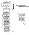
- Steps 202, 204, 206 operate in a loop to derive a measurement of the speed of the film by reading the "T-period" which is the time period between encoder pulses from the shaft encoder 90.
- the T-period is measured between the rising edges of the series of encoder pulses.
- steps 208, 210, 212, 214 the measured T-period is compared with MAX which is a stored value which represents the maximum film speed at which characters are printed at the correct aspect ratio on the film 50 whilst the print head 22 is operating at maximum rate.
- MAX is a stored value which represents the maximum film speed at which characters are printed at the correct aspect ratio on the film 50 whilst the print head 22 is operating at maximum rate.
- steps 208, 210, 212, 214 the measured T-period is compared with MAX which is a stored value which represents the maximum film speed at which characters are printed at the correct aspect ratio on the film 50 whilst the print head 22 is operating at maximum rate.
- MAX is a stored value which represents the maximum film speed at which characters are printed at the correct aspect ratio on the film 50 whilst the print head 22 is operating at maximum rate.
- step 208 if T-period is between MAX and MAX x 1.25 then after every four lines are printed, the next line is skipped. Thus a fifth of the lines are skipped on average which has the effect of compressing the character or pattern being printed by 4 / 5 . Since the film is measured as passing the head at 1.25 (i.e. 5 / 4 of the maximum printing speed, the effect of compressing by 4 / 5 is to restore the aspect ratio by bringing the character width back to 1 (i.e. normal width).
- steps 210, 212, 214 restore the aspect ratio for film speeds even greater than MAX up to the point in step 214 where the film speed is twice the speed equivalent to the maximum printing head speed which therefore requires every other line to be skipped to compress the characters or patterns by half in the direction of travel of the film 50.
- Steps 216 and 218 limit "T-Period" to be between MIN and MAX, namely the preferred minimum ribbon speed and the maximum speed respectively, the maximum speed being the speed which is equivalent to the maximum rate of the printhead as described above. T-Period is used in the ribbon control loop described below
- Figure 7 shows the process which controls ribbon speed by loading the T-period into the ribbon control segment of the software which ultimately controls the motor 18. This process matches the ribbon speed to the film speed as discussed above until the film speed reaches the speed equivalent to the maximum printing speed of the print head at which point the ribbon speed is kept constant until the film speed decreases below the speed equivalent to the maximum speed of the print head.
- the variable "ribsave” is used to adjust a variable "riblength” which maintains a record of the amount of ribbon remaining.
- the processor When the processor senses that all of the information relating to the required design has been supplied from memory 110 and has been fed to the print head 22, it issues a stop signal to the ribbon driver 104 to stop ribbon travel and the driver 98 for the print head motor 14 receives a signal causing the motor to withdraw the print head to its retracted, inactive position.
- a processor 94 then waits for the next trigger signal on 106 before repeating the above process. Further inputs 112 and 114 of the processor 94 are called respectively to a ribbon status sensor 116 and a ribbon break sensor 118 which are respectively associated with a spring loaded pivotable arm 120, seen in Figure 3.
- This arm 120 has a roller 122 at its distal end contacting the periphery of the ribbon supply on ribbon feed spool 36, so that when the ribbon supply runs low, an alarm can be activated and/or operation of the packaging apparatus of which the printer is part can be halted.
- the break sensor 118 is responsive to excessive clockwise movement of arm 60 (see Figure 3) to sense breakage of the ribbon 42 which, during normal operation, keeps roller 58 approximately in the position shown in Figure 3.
- roller 40 contains a clutch bearing 40C which is so mounted within the roller 40 that it is allowed to float in the sense that the centre of bearing 40C need not coincide exactly with the centre of the roller 40.
- Needle rollers of the clutch bearing which are self-locking when driven in one rotary direction, engage the outer surface of shaft or spindle 32 and drive is transferred from spindle 32 to the bearing 40C and thence via pins 40P to the roller 40.
- the floating nature of the clutch bearing 40C within the roller 40 allows for a degree of mismatch between the axis 128 of drive spindle 32 and that 130 of roller 40 when the cassette unit 12 is mounted on the base unit 10.
- the cassette unit 12 is located on base unit 10 by means of a retention pin 132 and a tubular socket 134, as shown in Figure 1.
Landscapes
- Impression-Transfer Materials And Handling Thereof (AREA)
- Electronic Switches (AREA)
- Adhesives Or Adhesive Processes (AREA)
- Electrochromic Elements, Electrophoresis, Or Variable Reflection Or Absorption Elements (AREA)
- Photographic Developing Apparatuses (AREA)
- Handling Of Continuous Sheets Of Paper (AREA)
- Handling Of Sheets (AREA)
Claims (6)
- Imprimante thermique pour imprimer sur un support d'impression continu par transfert d'encre à partir d'un ruban d'impression thermique, comprenant :un moyen définissant un trajet de support d'impression,une tête d'impression thermique comportant des éléments d'impression pouvant être alimentés et situés adjacents au trajet de support d'impression,un moyen définissant un trajet de ruban qui, lorsqu'il s'étend entre la tête d'impression et le trajet de support d'impression, s'étend dans la même direction que le trajet de support d'impression,un moyen d'entraínement de ruban pouvant fonctionner pour entraíner un ruban à des vitesses variables le long du trajet de ruban,un moyen de détection de vitesse pouvant fonctionner pour détecter la vitesse de déplacement du support d'impression le long du trajet de support d'impression, etun moyen de traitement comprenant un moyen formant mémoire et agencé, pendant l'impression, pour commander le moyen d'entraínement de ruban afin de faire varier la vitesse de ruban jusqu'à une vitesse maximale correspondant sensiblement à la vitesse maximale d'impression de la tête d'impression, et pour activer des éléments d'impression choisis en fonction de motifs de points prédéterminés mémorisés dans le moyen formant mémoire, pour provoquer le transfert d'encre du ruban vers le support d'impression pour former le motif prédéterminé, en tant que points d'encre, sur le support d'impression lorsqu'il passe devant la tête d'impression le long du trajet de support d'impression,le moyen de traitement étant en outre agencé pour gérer la vitesse du support d'impression en utilisant le moyen de détection de vitesse, et, lorsque la vitesse du support d'impression est supérieure à la vitesse de ruban, pour activer les éléments d'impression de façon que des points d'encre choisis soient omis du motif prédéterminé.
- Imprimante selon la revendication 1, dans laquelle le moyen de traitement est agencé pour faire que des points soient omis en sautant périodiquement un ensemble de points et en activant, à la place, les éléments en fonction de l'ensemble suivant de points mémorisés dans le moyen formant mémoire.
- Imprimante selon la revendication 2, dans laquelle le moyen de traitement est agencé pour sauter X ensembles en moyenne, où X= 1-(MAX/ vitesse du support d'impression) et où MAX est une vitesse de support d'impression correspondant sensiblement à la vitesse maximale d'impression de la tête d'impression.
- Imprimante selon la revendication 2, dans laquelle le moyen de traitement est agencé pour réduire, pour les deux ensembles de points sautés, la quantité de ruban amenée devant la tête d'impression d'une quantité sensiblement égale à la longueur de ruban utilisée pour imprimer un ensemble de points.
- Procédé d'économie de ruban dans une imprimante thermique pour imprimer sur un support d'impression continu par transfert d'encre à partir d'un ruban d'impression thermique, l'imprimante incluant une tête d'impression thermique comportant des éléments d'impression pouvant être alimentés, le procédé comprenant le passage d'un support d'impression devant la tête d'impression à une vitesse supérieure à la vitesse équivalant à la vitesse maximale d'impression de la tête d'impression, le passage du ruban devant la tête d'impression, dans la même direction que le support d'impression, à une vitesse équivalant à la vitesse maximale d'impression de la tête d'impression, en alimentant sélectivement les éléments d'impression pour transférer de l'encre pour constituer un motif de points d'encre prédéterminé sur le support et en omettant périodiquement des points du motif prédéterminé en sautant un ensemble de points du motif et en les remplaçant par un ensemble suivant de points.
- Procédé selon la revendication 5, incluant le saut de X ensembles en moyenne, où X= 1-(MAX/ vitesse du support d'impression) et où MAX est une vitesse de support d'impression correspondant sensiblement à la vitesse maximale d'impression de la tête.
Applications Claiming Priority (2)
| Application Number | Priority Date | Filing Date | Title |
|---|---|---|---|
| GBGB9613167.7A GB9613167D0 (en) | 1996-06-24 | 1996-06-24 | A printer for printing on a continuous print medium |
| GB9613167 | 1996-06-24 |
Publications (2)
| Publication Number | Publication Date |
|---|---|
| EP0816108A1 EP0816108A1 (fr) | 1998-01-07 |
| EP0816108B1 true EP0816108B1 (fr) | 2000-06-28 |
Family
ID=10795762
Family Applications (1)
| Application Number | Title | Priority Date | Filing Date |
|---|---|---|---|
| EP97302467A Expired - Lifetime EP0816108B1 (fr) | 1996-06-24 | 1997-04-10 | Imprimante pour imprimer sur un substrat d'enregistrement en forme de bande |
Country Status (8)
| Country | Link |
|---|---|
| EP (1) | EP0816108B1 (fr) |
| AT (1) | ATE194101T1 (fr) |
| AU (1) | AU685727B1 (fr) |
| CA (1) | CA2204819C (fr) |
| DE (1) | DE69702371T2 (fr) |
| GB (1) | GB9613167D0 (fr) |
| NO (1) | NO972929L (fr) |
| NZ (1) | NZ328123A (fr) |
Families Citing this family (1)
| Publication number | Priority date | Publication date | Assignee | Title |
|---|---|---|---|---|
| EP1016535B1 (fr) * | 1999-01-02 | 2006-07-19 | Scheidt & Bachmann Gmbh | Imprimante par transfert thermique |
Family Cites Families (10)
| Publication number | Priority date | Publication date | Assignee | Title |
|---|---|---|---|---|
| EP0036295A3 (fr) * | 1980-03-14 | 1981-10-07 | Printos B.V. | Appareil d'impression tenu à la main |
| JPS5783471A (en) * | 1980-11-14 | 1982-05-25 | Canon Inc | Thermal copying printer |
| US4933867A (en) * | 1983-05-31 | 1990-06-12 | Kabushiki Kaisha Toshiba | Printing apparatus |
| JPS6071275A (ja) * | 1983-09-28 | 1985-04-23 | Toshiba Corp | 画像出力装置 |
| JPS61108588A (ja) * | 1984-11-01 | 1986-05-27 | Hitachi Ltd | 記録紙送り制御方式 |
| US4915027A (en) * | 1987-03-28 | 1990-04-10 | Casio Computer Co., Ltd. | Hand-held manually operable printing apparatus |
| JPH0286480A (ja) * | 1988-09-22 | 1990-03-27 | Canon Inc | 熱転写記録装置 |
| US5372439A (en) * | 1992-12-18 | 1994-12-13 | Zebra Technologies Corporation | Thermal transfer printer with controlled ribbon feed |
| JPH06278334A (ja) * | 1993-01-27 | 1994-10-04 | Ricoh Co Ltd | 熱転写プリンタ |
| EP0635368A3 (fr) * | 1994-05-26 | 1995-09-06 | Illinois Tool Works | Méthode et appareil pour l'impression thermique économique. |
-
1996
- 1996-06-24 GB GBGB9613167.7A patent/GB9613167D0/en active Pending
-
1997
- 1997-04-10 AT AT97302467T patent/ATE194101T1/de not_active IP Right Cessation
- 1997-04-10 EP EP97302467A patent/EP0816108B1/fr not_active Expired - Lifetime
- 1997-04-10 DE DE69702371T patent/DE69702371T2/de not_active Expired - Lifetime
- 1997-05-08 CA CA002204819A patent/CA2204819C/fr not_active Expired - Fee Related
- 1997-05-14 AU AU20859/97A patent/AU685727B1/en not_active Ceased
- 1997-06-18 NZ NZ328123A patent/NZ328123A/en not_active IP Right Cessation
- 1997-06-23 NO NO972929A patent/NO972929L/no not_active Application Discontinuation
Also Published As
| Publication number | Publication date |
|---|---|
| DE69702371D1 (de) | 2000-08-03 |
| AU685727B1 (en) | 1998-01-22 |
| ATE194101T1 (de) | 2000-07-15 |
| CA2204819C (fr) | 2001-10-23 |
| NO972929D0 (no) | 1997-06-23 |
| DE69702371T2 (de) | 2001-03-29 |
| NO972929L (no) | 1997-12-29 |
| GB9613167D0 (en) | 1996-08-28 |
| EP0816108A1 (fr) | 1998-01-07 |
| NZ328123A (en) | 1998-09-24 |
| CA2204819A1 (fr) | 1997-12-24 |
Similar Documents
| Publication | Publication Date | Title |
|---|---|---|
| US5647679A (en) | Printer for printing on a continuous print medium | |
| US5816719A (en) | Printer for printing on a continuous print medium | |
| US5825374A (en) | Apparatus and method for advancing a web | |
| US5117241A (en) | Thermal printing apparatus with tensionless donor web during printing | |
| CN103921570B (zh) | 具备控制记录介质的张力的机构的打印机 | |
| US4685815A (en) | Printing apparatus | |
| US5971634A (en) | Method of printing | |
| US5294203A (en) | Ink ribbon feed | |
| KR0166427B1 (ko) | 프린터 및 용지를 인자부로 공급하는 방법 | |
| JPH10505554A (ja) | 高解像度のドナー/ダイレクト組み合わせ型サーマルプリンタ | |
| US5993092A (en) | Printer with reversible ribbon driving means for rewinding overshot ribbon | |
| EP2927007B1 (fr) | Procédé d'impression de corps en bande allongée, et dispositif d'impression | |
| EP0734876A2 (fr) | Imprimante pour imprimante sur un substrat d'enregistrement en forme de bande | |
| US7791627B2 (en) | Printer | |
| EP0842785B1 (fr) | Méthode de commande pour imprimante thermique | |
| US5372440A (en) | Printing machines | |
| EP0816108B1 (fr) | Imprimante pour imprimer sur un substrat d'enregistrement en forme de bande | |
| JPH06127063A (ja) | 感熱プリンタにおけるドナーウェブ位置決め装置 | |
| US20060227165A1 (en) | Method of Printing | |
| JP2958769B1 (ja) | サーマルスタンパ | |
| EP0602283A1 (fr) | Appareil d'enregistrement d'images thermique avec rouleau baladeur pour la commande de la tension du ruban donneur | |
| JP2025113770A (ja) | 印刷装置及び印刷装置の制御方法 | |
| JP2026006135A (ja) | 搬送装置、記録装置、及び搬送方法 | |
| CN116533659A (zh) | 一种用于同时生产多条织带的数码印花机 | |
| JP2000071490A (ja) | サーマルプリンタ |
Legal Events
| Date | Code | Title | Description |
|---|---|---|---|
| PUAI | Public reference made under article 153(3) epc to a published international application that has entered the european phase |
Free format text: ORIGINAL CODE: 0009012 |
|
| AK | Designated contracting states |
Kind code of ref document: A1 Designated state(s): AT BE CH DE DK ES FR GB GR IE IT LI LU NL PT SE |
|
| 17P | Request for examination filed |
Effective date: 19980615 |
|
| GRAG | Despatch of communication of intention to grant |
Free format text: ORIGINAL CODE: EPIDOS AGRA |
|
| 17Q | First examination report despatched |
Effective date: 19990623 |
|
| GRAG | Despatch of communication of intention to grant |
Free format text: ORIGINAL CODE: EPIDOS AGRA |
|
| GRAH | Despatch of communication of intention to grant a patent |
Free format text: ORIGINAL CODE: EPIDOS IGRA |
|
| GRAH | Despatch of communication of intention to grant a patent |
Free format text: ORIGINAL CODE: EPIDOS IGRA |
|
| GRAA | (expected) grant |
Free format text: ORIGINAL CODE: 0009210 |
|
| AK | Designated contracting states |
Kind code of ref document: B1 Designated state(s): AT BE CH DE DK ES FR GB GR IE IT LI LU NL PT SE |
|
| PG25 | Lapsed in a contracting state [announced via postgrant information from national office to epo] |
Ref country code: NL Free format text: LAPSE BECAUSE OF FAILURE TO SUBMIT A TRANSLATION OF THE DESCRIPTION OR TO PAY THE FEE WITHIN THE PRESCRIBED TIME-LIMIT Effective date: 20000628 Ref country code: LI Free format text: LAPSE BECAUSE OF FAILURE TO SUBMIT A TRANSLATION OF THE DESCRIPTION OR TO PAY THE FEE WITHIN THE PRESCRIBED TIME-LIMIT Effective date: 20000628 Ref country code: ES Free format text: THE PATENT HAS BEEN ANNULLED BY A DECISION OF A NATIONAL AUTHORITY Effective date: 20000628 Ref country code: CH Free format text: LAPSE BECAUSE OF FAILURE TO SUBMIT A TRANSLATION OF THE DESCRIPTION OR TO PAY THE FEE WITHIN THE PRESCRIBED TIME-LIMIT Effective date: 20000628 Ref country code: BE Free format text: LAPSE BECAUSE OF FAILURE TO SUBMIT A TRANSLATION OF THE DESCRIPTION OR TO PAY THE FEE WITHIN THE PRESCRIBED TIME-LIMIT Effective date: 20000628 Ref country code: AT Free format text: LAPSE BECAUSE OF FAILURE TO SUBMIT A TRANSLATION OF THE DESCRIPTION OR TO PAY THE FEE WITHIN THE PRESCRIBED TIME-LIMIT Effective date: 20000628 |
|
| REF | Corresponds to: |
Ref document number: 194101 Country of ref document: AT Date of ref document: 20000715 Kind code of ref document: T |
|
| RTI1 | Title (correction) |
Free format text: A PRINTER FOR PRINTING ON A CONTINUOUS PRINT MEDIUM |
|
| REG | Reference to a national code |
Ref country code: CH Ref legal event code: EP |
|
| REG | Reference to a national code |
Ref country code: IE Ref legal event code: FG4D |
|
| REF | Corresponds to: |
Ref document number: 69702371 Country of ref document: DE Date of ref document: 20000803 |
|
| ET | Fr: translation filed | ||
| ITF | It: translation for a ep patent filed | ||
| PG25 | Lapsed in a contracting state [announced via postgrant information from national office to epo] |
Ref country code: SE Free format text: LAPSE BECAUSE OF FAILURE TO SUBMIT A TRANSLATION OF THE DESCRIPTION OR TO PAY THE FEE WITHIN THE PRESCRIBED TIME-LIMIT Effective date: 20000928 Ref country code: PT Free format text: LAPSE BECAUSE OF FAILURE TO SUBMIT A TRANSLATION OF THE DESCRIPTION OR TO PAY THE FEE WITHIN THE PRESCRIBED TIME-LIMIT Effective date: 20000928 Ref country code: DK Free format text: LAPSE BECAUSE OF FAILURE TO SUBMIT A TRANSLATION OF THE DESCRIPTION OR TO PAY THE FEE WITHIN THE PRESCRIBED TIME-LIMIT Effective date: 20000928 |
|
| PG25 | Lapsed in a contracting state [announced via postgrant information from national office to epo] |
Ref country code: GR Free format text: LAPSE BECAUSE OF FAILURE TO SUBMIT A TRANSLATION OF THE DESCRIPTION OR TO PAY THE FEE WITHIN THE PRESCRIBED TIME-LIMIT Effective date: 20000929 |
|
| NLV1 | Nl: lapsed or annulled due to failure to fulfill the requirements of art. 29p and 29m of the patents act | ||
| REG | Reference to a national code |
Ref country code: CH Ref legal event code: PL |
|
| PG25 | Lapsed in a contracting state [announced via postgrant information from national office to epo] |
Ref country code: LU Free format text: LAPSE BECAUSE OF NON-PAYMENT OF DUE FEES Effective date: 20010410 Ref country code: IE Free format text: LAPSE BECAUSE OF NON-PAYMENT OF DUE FEES Effective date: 20010410 |
|
| PLBE | No opposition filed within time limit |
Free format text: ORIGINAL CODE: 0009261 |
|
| STAA | Information on the status of an ep patent application or granted ep patent |
Free format text: STATUS: NO OPPOSITION FILED WITHIN TIME LIMIT |
|
| 26N | No opposition filed | ||
| REG | Reference to a national code |
Ref country code: GB Ref legal event code: IF02 |
|
| REG | Reference to a national code |
Ref country code: IE Ref legal event code: MM4A |
|
| PGFP | Annual fee paid to national office [announced via postgrant information from national office to epo] |
Ref country code: FR Payment date: 20130506 Year of fee payment: 17 |
|
| REG | Reference to a national code |
Ref country code: FR Ref legal event code: ST Effective date: 20141231 |
|
| PG25 | Lapsed in a contracting state [announced via postgrant information from national office to epo] |
Ref country code: FR Free format text: LAPSE BECAUSE OF NON-PAYMENT OF DUE FEES Effective date: 20140430 |
|
| PGFP | Annual fee paid to national office [announced via postgrant information from national office to epo] |
Ref country code: DE Payment date: 20160427 Year of fee payment: 20 Ref country code: GB Payment date: 20160427 Year of fee payment: 20 |
|
| PGFP | Annual fee paid to national office [announced via postgrant information from national office to epo] |
Ref country code: IT Payment date: 20160421 Year of fee payment: 20 |
|
| REG | Reference to a national code |
Ref country code: DE Ref legal event code: R071 Ref document number: 69702371 Country of ref document: DE |
|
| REG | Reference to a national code |
Ref country code: GB Ref legal event code: PE20 Expiry date: 20170409 |
|
| PG25 | Lapsed in a contracting state [announced via postgrant information from national office to epo] |
Ref country code: GB Free format text: LAPSE BECAUSE OF EXPIRATION OF PROTECTION Effective date: 20170409 |