EP0816189B1 - Dispositif de sécurité pour véhicules - Google Patents
Dispositif de sécurité pour véhicules Download PDFInfo
- Publication number
- EP0816189B1 EP0816189B1 EP97111315A EP97111315A EP0816189B1 EP 0816189 B1 EP0816189 B1 EP 0816189B1 EP 97111315 A EP97111315 A EP 97111315A EP 97111315 A EP97111315 A EP 97111315A EP 0816189 B1 EP0816189 B1 EP 0816189B1
- Authority
- EP
- European Patent Office
- Prior art keywords
- safety device
- igniter
- set forth
- cylinder tube
- embedded
- Prior art date
- Legal status (The legal status is an assumption and is not a legal conclusion. Google has not performed a legal analysis and makes no representation as to the accuracy of the status listed.)
- Expired - Lifetime
Links
- 239000000463 material Substances 0.000 claims description 10
- 239000011810 insulating material Substances 0.000 claims description 3
- 238000007373 indentation Methods 0.000 claims description 2
- 239000007787 solid Substances 0.000 claims description 2
- 230000006835 compression Effects 0.000 claims 2
- 238000007906 compression Methods 0.000 claims 2
- 238000007789 sealing Methods 0.000 claims 1
- 238000009434 installation Methods 0.000 description 2
- 244000089486 Phragmites australis subsp australis Species 0.000 description 1
Images

Classifications
-
- F—MECHANICAL ENGINEERING; LIGHTING; HEATING; WEAPONS; BLASTING
- F42—AMMUNITION; BLASTING
- F42C—AMMUNITION FUZES; ARMING OR SAFETY MEANS THEREFOR
- F42C19/00—Details of fuzes
- F42C19/08—Primers; Detonators
- F42C19/12—Primers; Detonators electric
-
- B—PERFORMING OPERATIONS; TRANSPORTING
- B60—VEHICLES IN GENERAL
- B60R—VEHICLES, VEHICLE FITTINGS, OR VEHICLE PARTS, NOT OTHERWISE PROVIDED FOR
- B60R22/00—Safety belts or body harnesses in vehicles
- B60R22/34—Belt retractors, e.g. reels
- B60R22/46—Reels with means to tension the belt in an emergency by forced winding up
- B60R22/4628—Reels with means to tension the belt in an emergency by forced winding up characterised by fluid actuators, e.g. pyrotechnic gas generators
- B60R22/4633—Linear actuators, e.g. comprising a piston moving along reel axis and rotating along its own axis
-
- F—MECHANICAL ENGINEERING; LIGHTING; HEATING; WEAPONS; BLASTING
- F42—AMMUNITION; BLASTING
- F42B—EXPLOSIVE CHARGES, e.g. FOR BLASTING, FIREWORKS, AMMUNITION
- F42B3/00—Blasting cartridges, i.e. case and explosive
- F42B3/04—Blasting cartridges, i.e. case and explosive for producing gas under pressure
-
- B—PERFORMING OPERATIONS; TRANSPORTING
- B60—VEHICLES IN GENERAL
- B60R—VEHICLES, VEHICLE FITTINGS, OR VEHICLE PARTS, NOT OTHERWISE PROVIDED FOR
- B60R21/00—Arrangements or fittings on vehicles for protecting or preventing injuries to occupants or pedestrians in case of accidents or other traffic risks
- B60R21/02—Occupant safety arrangements or fittings, e.g. crash pads
- B60R21/16—Inflatable occupant restraints or confinements designed to inflate upon impact or impending impact, e.g. air bags
- B60R21/26—Inflatable occupant restraints or confinements designed to inflate upon impact or impending impact, e.g. air bags characterised by the inflation fluid source or means to control inflation fluid flow
- B60R2021/26029—Ignitors
Definitions
- the invention relates to a safety device for Vehicles, in particular a linear drive for a belt tensioner or an inflator for an airbag, with inside one Cylinder tube arranged adjacent to the cylinder wall pyrotechnic gas generator material and an electrical Detonators.
- the invention provides a security device for Vehicles that reduce mechanical stress on the one hand is exposed and on the other hand by a lesser Features space in the lateral direction, so that the linear drive or the inflator is more compact.
- This will be one Safety device of the type mentioned in the introduction thereby achieved that the igniter is parallel to the cylinder axis elongated body formed and on the outside of the lateral surface of the Cylinder tube attached to a through opening on this is.
- the longitudinal axis of the ignition unit therefore extends not at right angles to the cylinder axis as was previously the case, but instead parallel to it, so that the ignition unit is hardly on the side Cylinder tube protrudes.
- the igniter is attached to the cylinder barrel, i.e.
- the igniter can be separated from the cylinder tube with the gas generator material inside be transported so that an unwanted ignition of the pyrotechnic material is avoided during transport.
- the safety device preferably has an igniter with a solidly formed of insulating material Body into which a squib, i.e. one of ignition material surrounded ignition resistance, is embedded.
- the squib is the through opening of the cylinder tube, in particular in protruding them, opposite. This results in a desired one small distance from the gas generator material.
- the cable connected to the squib preferably emerges from the end out of the body so that it does not stick out sideways, and is further preferably curved in the body of the detonator embedded so that the junction on the squib is relieved of strain.
- the igniter is switched off in accordance with the preferred embodiment a strap is attached to the cylinder barrel.
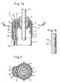
- Fig. 1a is a linear drive 1 of a belt tensioner shown, which has a cylinder tube 3 in which a piston an adjacent piston rod 4 is slidably disposed.
- a cylinder tube 3 in which a piston an adjacent piston rod 4 is slidably disposed.
- a thin casing 5 in the Inside of the cylinder tube 3 borders on the cylinder wall, from this is only separated by a thin casing 5, pyrotechnic gas generator material 6.
- On the outside Shell surface of the cylinder tube 3 is by a strap 7, the an electric detonator 9 is produced from a tubular profile attached.
- the strap 7 encloses the igniter 9 and that Cylinder tube 3 and presses the igniter 9 with its inside 11 against the cylinder barrel 3.
- cylinder tube 3 also may have an opening 15b, in which a corresponding shaped bulge 17a extends.
- the igniter 9 is designed as an elongated body that Fixed parallel to the cylinder axis on the cylinder tube 3 and solid is formed from insulating material 13. In the body is one Embedded cable 21, which protrudes from the end of it. A high-frequency choke is also embedded in the body 23 and a subsequent squib 25. The Lead wires of the squib 25 are towards the inside 11 bent at right angles.
- the squib 25 protrudes slightly from the body and protrudes in the assembled state of the igniter 9 into a through opening 29 in the cylinder tube 3, which leads to the gas generator material 6.
- the axial position of the igniter 9 must thus be in relation to the cylinder tube 3 be aligned that the squib 25 always to the Through opening 29 adjoins or protrudes into it.
- the detonator 9 has its body on its top a nose 31 protruding towards the cylinder tube 3, the attacks on the end face of the cylinder tube 3 and in their shape the outer contour of the cylinder tube 3 is adapted.
- a seal 33 encloses this Cable 21.
- Another seal 35 surrounds the squib 25 and lies sealingly on the outer surface of the cylinder tube 3.
- Extensions 41 on the outside of the body hold the Clamping ring 7 additionally at least in the axial direction on the body.
- the igniter 9 Due to the elongated design of the igniter 9 less space in the vehicle for the entire safety device needed.
- the igniter 9 can be relatively long, which makes it Bracket on the cylinder tube 3 is improved.
Landscapes
- Engineering & Computer Science (AREA)
- General Engineering & Computer Science (AREA)
- Mechanical Engineering (AREA)
- Air Bags (AREA)
- Automotive Seat Belt Assembly (AREA)
- Electrical Discharge Machining, Electrochemical Machining, And Combined Machining (AREA)
Claims (11)
- Dispositif de sécurité pour des véhicules, en particulier mécanisme d'entraínement linéaire d'un tendeur de ceinture ou d'une unité de gonflage pour un sac à gaz , avec à l'intérieur d'un tube cylindrique (3) une matière (6) de générateur pyrotechnique disposée de façon adjacente à la paroi du cylindre et avec un allumeur électrique (9), caractérisé en ce que l'allumeur (9) est constitué sous la forme d'un corps s'étendant parallèlement à l'axe du cylindre et est attaché à celui-ci à l'extérieur sur la surface enveloppe du tube cylindrique (3) en face d'un orifice de passage (29) dans celui-ci.
- Dispositif de sécurité selon la revendication 1, caractérisé en ce que l'on noie dans le corps formé d'une matière isolante (13) une pastille d'allumage (25), qui se trouve en face de l'orifice de passage (29) du tube cylindrique (3), en pénétrant en particulier dans celui-ci.
- Dispositif de sécurité selon la revendication 2, caractérisé en ce que l'on raccorde un câble (21), qui est noyé également dans la masse du corps, à la pastille d'allumage (25), câble qui sort du corps du côté frontal.
- Dispositif de sécurité selon la revendication 3, caractérisé en ce que l'on noie dans le corps de l'allumeur (9) un joint d'étanchéité (33; 35), qui entoure le câble (21).
- Dispositif de sécurité selon la revendication 4, caractérisé en ce que le câble (21) est noyé dans le corps de l'allumeur (9) en formant une courbe.
- Dispositif de sécurité selon l'une des revendications 2 à 5,
caractérisé en ce que l'on noie dans le corps de l'allumeur (9) un joint d'étanchéité (35), qui entoure la pastille d'allumage (25), et qui repose de façon étanche sur la surface enveloppe du tube cylindrique (3). - Dispositif de sécurité selon l'une des revendications précédentes, caractérisé en ce que le corps de l'allumeur (9) sur le tube cylindrique (3) est fixé par une bande de serrage (7), qui entoure les deux.
- Dispositif de sécurité selon la revendication 7 et la revendication 5 ou 6, caractérisé en ce que le corps de l'allumeur (9) présente au moins une saillie (39) qui repose sur la surface enveloppe du tube cylindrique (3) et qui augmente le serrage, causé par la bande de serrage (7), localement vis-à-vis du joint d'étanchéité (37).
- Dispositif de sécurité selon la revendication 7 ou 8, caractérisé en ce que le corps de l'allumeur (9) présente au moins une saillie (39), qui repose sur la bande de serrage (7), et qui augmente le serrage causé par la. bande de serrage (7) vis-à-vis du joint d'étanchéité (33, 35; 37).
- Dispositif de sécurité selon l'une des revendications précédentes, caractérisé en ce que l'on prévoit sur le corps des prolongements (41), qui servent à maintenir la bande de serrage (7).
- Dispositif de sécurité selon l'une des revendications précédentes, caractérisé en ce que le tube cylindrique (3) présente au moins un bombement vers l'intérieur (15), dans lequel s'enfonce un prolongement correspondant (17) sur le côté intérieur de la bande de serrage (7).
Applications Claiming Priority (2)
| Application Number | Priority Date | Filing Date | Title |
|---|---|---|---|
| DE29611657U DE29611657U1 (de) | 1996-07-04 | 1996-07-04 | Sicherheitseinrichtung für Fahrzeuge |
| DE29611657U | 1996-07-04 |
Publications (3)
| Publication Number | Publication Date |
|---|---|
| EP0816189A2 EP0816189A2 (fr) | 1998-01-07 |
| EP0816189A3 EP0816189A3 (fr) | 2000-10-11 |
| EP0816189B1 true EP0816189B1 (fr) | 2003-05-21 |
Family
ID=8026063
Family Applications (1)
| Application Number | Title | Priority Date | Filing Date |
|---|---|---|---|
| EP97111315A Expired - Lifetime EP0816189B1 (fr) | 1996-07-04 | 1997-07-04 | Dispositif de sécurité pour véhicules |
Country Status (6)
| Country | Link |
|---|---|
| US (1) | US5876063A (fr) |
| EP (1) | EP0816189B1 (fr) |
| JP (1) | JPH1059129A (fr) |
| BR (1) | BR9703859A (fr) |
| DE (2) | DE29611657U1 (fr) |
| ES (1) | ES2111513T3 (fr) |
Cited By (1)
| Publication number | Priority date | Publication date | Assignee | Title |
|---|---|---|---|---|
| DE102004005687B4 (de) * | 2004-02-05 | 2018-05-17 | Trw Automotive Gmbh | Gurtstraffersystem für Kraftfahrzeuge |
Families Citing this family (6)
| Publication number | Priority date | Publication date | Assignee | Title |
|---|---|---|---|---|
| DE29707352U1 (de) * | 1997-04-23 | 1997-08-21 | Trw Occupant Restraint Systems Gmbh, 73551 Alfdorf | Straffer für einen Sicherheitsgurt |
| US6357785B1 (en) * | 1997-08-12 | 2002-03-19 | Trw Occupant Restraint Systems Gmbh & Co. Kg | Gas bag module for a vehicle occupant restraint system |
| DE29921493U1 (de) | 1999-12-07 | 2000-04-13 | TRW Occupant Restraint Systems GmbH & Co. KG, 73553 Alfdorf | Zünder und Gasgenerator zur Verwendung in Rückhaltesystemen für Fahrzeuginsassen |
| DE102007005305B4 (de) * | 2006-02-23 | 2014-02-20 | Autoliv Development Ab | Gassackanordnung |
| DE102016104127A1 (de) * | 2016-03-07 | 2017-09-07 | Witte Automotive Gmbh | Türgriffanordnung |
| DE102019206439B4 (de) * | 2019-05-06 | 2021-11-11 | Autoliv Development Ab | Gurtaufroller |
Family Cites Families (12)
| Publication number | Priority date | Publication date | Assignee | Title |
|---|---|---|---|---|
| US3532359A (en) * | 1968-07-22 | 1970-10-06 | Chrysler Corp | Inflatable device |
| US3797854A (en) * | 1971-06-14 | 1974-03-19 | Rocket Research Corp | Crash restraint air generating inflation system |
| US3891233A (en) * | 1974-06-20 | 1975-06-24 | Allied Chem | Inflator seal |
| US4165691A (en) * | 1977-08-29 | 1979-08-28 | Atlas Powder Company | Delay detonator and its use with explosive packaged boosters and cartridges |
| US4370930A (en) * | 1980-12-29 | 1983-02-01 | Ford Motor Company | End cap for a propellant container |
| SU1310022A1 (ru) * | 1983-11-25 | 1987-05-15 | Таллинский Политехнический Институт | Лабораторна дезинтеграторна установка |
| DE8437589U1 (de) * | 1984-12-21 | 1986-07-03 | Autoflug GmbH & Co Fahrzeugtechnik, 2084 Rellingen | Rücksitz-Sicherheitsgurt für Kraftfahrzeuge |
| US4858951A (en) * | 1988-05-04 | 1989-08-22 | Trw Vehicle Safety Systems, Inc. | Igniter for gas generating material |
| DE4230665A1 (de) * | 1992-09-14 | 1994-03-17 | Takata Europ Gmbh | Sicherheitsgurtanordnung für Fahrzeuge |
| ZA948566B (en) * | 1993-11-18 | 1995-05-18 | Ici America Inc | Airbag igniter and method of manufacture |
| WO1996004154A1 (fr) * | 1994-08-04 | 1996-02-15 | Alliedsignal Inc. | Procede et appareil permettant de reduire le risque de blessure pour les passagers d'un vehicule dans les collisions frontales |
| DE29612781U1 (de) * | 1996-07-23 | 1996-11-21 | Trw Occupant Restraint Systems Gmbh, 73551 Alfdorf | Pyrotechnische Linearantriebseinrichtung für einen Gurtstraffer |
-
1996
- 1996-07-04 DE DE29611657U patent/DE29611657U1/de not_active Expired - Lifetime
-
1997
- 1997-07-03 BR BR9703859A patent/BR9703859A/pt not_active Application Discontinuation
- 1997-07-03 JP JP9177494A patent/JPH1059129A/ja active Pending
- 1997-07-03 US US08/887,771 patent/US5876063A/en not_active Expired - Fee Related
- 1997-07-04 ES ES97111315T patent/ES2111513T3/es not_active Expired - Lifetime
- 1997-07-04 DE DE59710107T patent/DE59710107D1/de not_active Expired - Fee Related
- 1997-07-04 EP EP97111315A patent/EP0816189B1/fr not_active Expired - Lifetime
Cited By (1)
| Publication number | Priority date | Publication date | Assignee | Title |
|---|---|---|---|---|
| DE102004005687B4 (de) * | 2004-02-05 | 2018-05-17 | Trw Automotive Gmbh | Gurtstraffersystem für Kraftfahrzeuge |
Also Published As
| Publication number | Publication date |
|---|---|
| ES2111513T1 (es) | 1998-03-16 |
| BR9703859A (pt) | 1998-08-11 |
| ES2111513T3 (es) | 2004-02-16 |
| DE59710107D1 (de) | 2003-06-26 |
| EP0816189A3 (fr) | 2000-10-11 |
| DE29611657U1 (de) | 1996-11-07 |
| US5876063A (en) | 1999-03-02 |
| JPH1059129A (ja) | 1998-03-03 |
| EP0816189A2 (fr) | 1998-01-07 |
Similar Documents
| Publication | Publication Date | Title |
|---|---|---|
| EP1960237B1 (fr) | Module de poche a gaz | |
| DE60105351T2 (de) | Sicherheitsgurtroller | |
| DE29612781U1 (de) | Pyrotechnische Linearantriebseinrichtung für einen Gurtstraffer | |
| EP0614789A1 (fr) | Prétendeur pour systèmes de ceinture de sécurité pour véhicules | |
| EP0694444A2 (fr) | Système de sac gonflable | |
| DE19922674A1 (de) | Pyrotechnischer Aktuator | |
| EP0803412B1 (fr) | Système de ceinture de sécurité | |
| DE4324554B4 (de) | Gasgenerator, insbesondere für einen Airbag | |
| DE4415373A1 (de) | Gasgenerator für ein Fahrzeug-Rückhaltesystem | |
| DE69802221T2 (de) | Pyrotechnischer Gasgenerator mit einstellbarem Gasdurchsatz und -volumen für einen Airbag | |
| EP0816189A2 (fr) | Dispositif de sécurité pour véhicules | |
| EP0614790A1 (fr) | Prétendeur pour systèmes de ceinture de sécurité dans les véhicules | |
| DE102006053563B4 (de) | Gurtstraffer für ein Sicherheitsgurtsystem | |
| DE69307443T2 (de) | Gasgenerator zum Aufblasen eines Luftkissens | |
| EP0798177B1 (fr) | Système de retenue des occupants de véhicule avec un tendeur de sangle | |
| DE69319105T2 (de) | Packung für eine gaserzeugende Ladung für ein Gaskissen-Gasgenerator | |
| DE10328603A1 (de) | Airbagabdichtung | |
| DE102017220724A1 (de) | Energiespeicher für ein Kraftfahrzeug sowie entsprechendes Kraftfahrzeug | |
| EP1535810A2 (fr) | Générateur de gaz | |
| DE102012002719B4 (de) | Pyrotechnischer Straffer | |
| DE19633696B4 (de) | Airbagabdeckklappe | |
| DE102007034401A1 (de) | Gurtstraffer | |
| DE102004028049A1 (de) | Vorrichtung zum Straffen eines Sicherheitsgurts mit pyrotechnischem Linearantrieb | |
| DE20218869U1 (de) | Gurtstraffer | |
| DE202013104757U1 (de) | Auslösevorrichtung für einen Gurtstraffer |
Legal Events
| Date | Code | Title | Description |
|---|---|---|---|
| PUAI | Public reference made under article 153(3) epc to a published international application that has entered the european phase |
Free format text: ORIGINAL CODE: 0009012 |
|
| AK | Designated contracting states |
Kind code of ref document: A2 Designated state(s): DE ES FR GB IT |
|
| ITCL | It: translation for ep claims filed |
Representative=s name: DR. ING. A. RACHELI & C. |
|
| GBC | Gb: translation of claims filed (gb section 78(7)/1977) | ||
| REG | Reference to a national code |
Ref country code: ES Ref legal event code: BA2A Ref document number: 2111513 Country of ref document: ES Kind code of ref document: T1 |
|
| EL | Fr: translation of claims filed | ||
| RAP1 | Party data changed (applicant data changed or rights of an application transferred) |
Owner name: TRW OCCUPANT RESTRAINT SYSTEMS GMBH & CO. KG |
|
| PUAL | Search report despatched |
Free format text: ORIGINAL CODE: 0009013 |
|
| AK | Designated contracting states |
Kind code of ref document: A3 Designated state(s): AT BE CH DE DK ES FI FR GB GR IE IT LI LU MC NL PT SE |
|
| 17P | Request for examination filed |
Effective date: 20010102 |
|
| AKX | Designation fees paid |
Free format text: DE ES FR GB IT |
|
| GRAH | Despatch of communication of intention to grant a patent |
Free format text: ORIGINAL CODE: EPIDOS IGRA |
|
| GRAH | Despatch of communication of intention to grant a patent |
Free format text: ORIGINAL CODE: EPIDOS IGRA |
|
| GRAA | (expected) grant |
Free format text: ORIGINAL CODE: 0009210 |
|
| AK | Designated contracting states |
Designated state(s): DE ES FR GB IT |
|
| REG | Reference to a national code |
Ref country code: GB Ref legal event code: FG4D Free format text: NOT ENGLISH |
|
| PGFP | Annual fee paid to national office [announced via postgrant information from national office to epo] |
Ref country code: GB Payment date: 20030612 Year of fee payment: 7 |
|
| REF | Corresponds to: |
Ref document number: 59710107 Country of ref document: DE Date of ref document: 20030626 Kind code of ref document: P |
|
| PGFP | Annual fee paid to national office [announced via postgrant information from national office to epo] |
Ref country code: ES Payment date: 20030723 Year of fee payment: 7 |
|
| GBT | Gb: translation of ep patent filed (gb section 77(6)(a)/1977) |
Effective date: 20030804 |
|
| REG | Reference to a national code |
Ref country code: ES Ref legal event code: FG2A Ref document number: 2111513 Country of ref document: ES Kind code of ref document: T3 |
|
| ET | Fr: translation filed | ||
| PLBE | No opposition filed within time limit |
Free format text: ORIGINAL CODE: 0009261 |
|
| STAA | Information on the status of an ep patent application or granted ep patent |
Free format text: STATUS: NO OPPOSITION FILED WITHIN TIME LIMIT |
|
| 26N | No opposition filed |
Effective date: 20040224 |
|
| PG25 | Lapsed in a contracting state [announced via postgrant information from national office to epo] |
Ref country code: GB Free format text: LAPSE BECAUSE OF NON-PAYMENT OF DUE FEES Effective date: 20040704 |
|
| PG25 | Lapsed in a contracting state [announced via postgrant information from national office to epo] |
Ref country code: ES Free format text: LAPSE BECAUSE OF NON-PAYMENT OF DUE FEES Effective date: 20040705 |
|
| GBPC | Gb: european patent ceased through non-payment of renewal fee |
Effective date: 20040704 |
|
| PG25 | Lapsed in a contracting state [announced via postgrant information from national office to epo] |
Ref country code: IT Free format text: LAPSE BECAUSE OF NON-PAYMENT OF DUE FEES Effective date: 20050704 |
|
| PGFP | Annual fee paid to national office [announced via postgrant information from national office to epo] |
Ref country code: FR Payment date: 20050706 Year of fee payment: 9 |
|
| PGFP | Annual fee paid to national office [announced via postgrant information from national office to epo] |
Ref country code: DE Payment date: 20050729 Year of fee payment: 9 |
|
| REG | Reference to a national code |
Ref country code: ES Ref legal event code: FD2A Effective date: 20040705 |
|
| PG25 | Lapsed in a contracting state [announced via postgrant information from national office to epo] |
Ref country code: DE Free format text: LAPSE BECAUSE OF NON-PAYMENT OF DUE FEES Effective date: 20070201 |
|
| REG | Reference to a national code |
Ref country code: FR Ref legal event code: ST Effective date: 20070330 |
|
| PG25 | Lapsed in a contracting state [announced via postgrant information from national office to epo] |
Ref country code: FR Free format text: LAPSE BECAUSE OF NON-PAYMENT OF DUE FEES Effective date: 20060731 |