EP0816272A1 - Stapelgreifer - Google Patents
Stapelgreifer Download PDFInfo
- Publication number
- EP0816272A1 EP0816272A1 EP97109230A EP97109230A EP0816272A1 EP 0816272 A1 EP0816272 A1 EP 0816272A1 EP 97109230 A EP97109230 A EP 97109230A EP 97109230 A EP97109230 A EP 97109230A EP 0816272 A1 EP0816272 A1 EP 0816272A1
- Authority
- EP
- European Patent Office
- Prior art keywords
- stack
- support
- receiving space
- gripper
- hold
- Prior art date
- Legal status (The legal status is an assumption and is not a legal conclusion. Google has not performed a legal analysis and makes no representation as to the accuracy of the status listed.)
- Granted
Links
Images
Classifications
-
- B—PERFORMING OPERATIONS; TRANSPORTING
- B65—CONVEYING; PACKING; STORING; HANDLING THIN OR FILAMENTARY MATERIAL
- B65H—HANDLING THIN OR FILAMENTARY MATERIAL, e.g. SHEETS, WEBS, CABLES
- B65H31/00—Pile receivers
- B65H31/32—Auxiliary devices for receiving articles during removal of a completed pile
-
- B—PERFORMING OPERATIONS; TRANSPORTING
- B65—CONVEYING; PACKING; STORING; HANDLING THIN OR FILAMENTARY MATERIAL
- B65H—HANDLING THIN OR FILAMENTARY MATERIAL, e.g. SHEETS, WEBS, CABLES
- B65H31/00—Pile receivers
- B65H31/30—Arrangements for removing completed piles
-
- B—PERFORMING OPERATIONS; TRANSPORTING
- B65—CONVEYING; PACKING; STORING; HANDLING THIN OR FILAMENTARY MATERIAL
- B65H—HANDLING THIN OR FILAMENTARY MATERIAL, e.g. SHEETS, WEBS, CABLES
- B65H31/00—Pile receivers
- B65H31/30—Arrangements for removing completed piles
- B65H31/3036—Arrangements for removing completed piles by gripping the pile
- B65H31/3045—Arrangements for removing completed piles by gripping the pile on the outermost articles of the pile for clamping the pile
-
- B—PERFORMING OPERATIONS; TRANSPORTING
- B65—CONVEYING; PACKING; STORING; HANDLING THIN OR FILAMENTARY MATERIAL
- B65H—HANDLING THIN OR FILAMENTARY MATERIAL, e.g. SHEETS, WEBS, CABLES
- B65H31/00—Pile receivers
- B65H31/30—Arrangements for removing completed piles
- B65H31/3054—Arrangements for removing completed piles by moving the surface supporting the lowermost article of the pile, e.g. by using belts or rollers
- B65H31/3063—Arrangements for removing completed piles by moving the surface supporting the lowermost article of the pile, e.g. by using belts or rollers by special supports like carriages, containers, trays, compartments, plates or bars, e.g. moved in a closed loop
-
- B—PERFORMING OPERATIONS; TRANSPORTING
- B65—CONVEYING; PACKING; STORING; HANDLING THIN OR FILAMENTARY MATERIAL
- B65H—HANDLING THIN OR FILAMENTARY MATERIAL, e.g. SHEETS, WEBS, CABLES
- B65H2301/00—Handling processes for sheets or webs
- B65H2301/40—Type of handling process
- B65H2301/42—Piling, depiling, handling piles
- B65H2301/422—Handling piles, sets or stacks of articles
- B65H2301/4224—Gripping piles, sets or stacks of articles
-
- B—PERFORMING OPERATIONS; TRANSPORTING
- B65—CONVEYING; PACKING; STORING; HANDLING THIN OR FILAMENTARY MATERIAL
- B65H—HANDLING THIN OR FILAMENTARY MATERIAL, e.g. SHEETS, WEBS, CABLES
- B65H2301/00—Handling processes for sheets or webs
- B65H2301/40—Type of handling process
- B65H2301/42—Piling, depiling, handling piles
- B65H2301/422—Handling piles, sets or stacks of articles
- B65H2301/4225—Handling piles, sets or stacks of articles in or on special supports
Definitions
- the present invention relates to a stack gripper the preamble of claim 1.
- stack grippers are known and are used to stack palletizing printed products using a robotic arm.
- the stack gripper is at the end of a robot arm attached and takes the stack from a feeder, to then place the stack on a pallet.
- the stack falls within of the stack gripper no longer at a specific one Way because the stacking pad is in the area of the lower end of the Leadership is arranged. Since the pile support is supported by a Horizontal movement is movable out of the stack receiving space, this can be "pulled away" from under the stack, the Stack is still held on all sides by the guide. Consequently the bottom of the stack just slides off the guide, however, does not make a falling motion.
- the stack gripper according to the invention is very compact because the The height of the stack gripper is approximately the maximum stack height corresponds.
- the operation of the invention Stack gripper very quiet, since no flaps or Fingers are present at very high speed would have to be folded against a stop to get one To release the fall path.
- the stacking support can be at least one as a support element Adjusting cylinder, preferably have a telescopic cylinder.
- a telescopic cylinder By using such a cylinder the stack support completely from the stack receiving space remove it without it sticking far into the room. This is of particular advantage because of the work area of the robot should always be kept as small as possible should.
- a telescopic cylinder that parts are prevented when the stacking support is open protrude from the outside of the stacking gripper so that the Keep the robot's work area as small as possible can be.
- the Stacking support at least one flexible support tape.
- a band-like edition created in a stack gripper that extends from the bottom "unroll" of the stack without a relative movement between the stacking pad and the bottom product of the stack takes place.
- This Stacking can by a telescopic cylinder or also be moved into the receiving space by a push chain.
- a push chain is composed of individual links and can be made from the straight form in just one Bend towards. If such a push chain is without band-like support used as a support element, so can the stack on such a push chain or several Push chains are stored.
- a particularly advantageous embodiment of the invention is given when the breakpoint of the upper run of the Support tape when pulling out the lower run by one predetermined path against the direction of movement of the stack support is movable.
- the stacking pad i.e. of the actuating cylinder surrounded by the support tape the stack does not fall through. However, it follows a certain height offset at the bottom of the stack, when the stacking pad is pulled out of the stacking space becomes. This height offset leads to that the side of the stack from which the stack holder is located moved away, some offset occurs, i.e. the Products with their edges are not exactly on top of each other.
- the embodiment described above can however, the upper run of the support tape when pulling out the lower run by a predetermined path, namely the Offset, opposite to the direction of movement of the stacking support move, causing the lower stack area, which is not completely aligned, together with the upper run against the direction of movement of the stacking support shifts.
- This will make the bottom stack area again properly aligned so that the outer edges of the Form a stack of vertical surfaces.
- the sliding attachment the stop of the upper run can be, for example with a spring-loaded attachment of the stopping point achieve.
- the breakpoint can also be controlled to one certain time shifted by the predetermined distance be, the time can be chosen so that the resulting offset is optimally compensated, for example approximately in the middle of the pull-out movement of the stacking support.
- At least one hold-down device within the stack receiving space provided that is adjustable against the top of the stack is. This ensures that the (very fast) Movement of the robot arm no deformation of the stack occurs and that no products, such as single sheets, detach from the top of the stack. Especially if the all-round leadership is not closed, but is formed, for example, by corner rails, remains Between these corner rails there is an air space which, under certain circumstances the top products at a fast Motion whirls up. It is particularly advantageous here if the hold-down device within the entire stack receiving space is vertically adjustable, because then also with varying Stack height or for stacks consisting of just a few Products, hold down is possible.
- the hold-down viewed from above, is arranged above the stack support. In this case it runs the force that the hold-down device exerts is exactly vertical to the stacking support so that the stack is not deflects but between the hold-down device and the stack support is clamped.
- Hold-down results in a particularly advantageous Procedure, because in this case the hold-down too then press the discarded stack when the Stack gripper is already raised.
- the hold-down will So moved in the opposite direction to the stack gripper movement and put pressure on the stack until the Hold-down has reached its lower end stop.
- the stack is held together as a compact package, until the stack gripper is completely up from the stack is lifted off. Any friction between the products and the leadership does not have a negative impact on the Stack alignment. Also has a possible draft that is caused by the start of the stack gripper, no influence on the alignment of the stack.
- a Signal generator can be provided at the lower end of the Hold-down device is arranged.
- a signal generator can be held down by the hold-down device when lifting the Stack gripper has reached its lower end point Generate signal, for example with the help of Robot controller generates a height measurement. So you can the exact stack height after each stacking determine by using the respective robot controller Height value is read out when the signal transmitter responds.
- This represents one compared to ultrasonic sensors or the like represents a much more reliable solution averaging individually determined height measurements for a location, this mean value being used for the following Stack position is used.
- Two hold-down devices are preferred provided that each cooperate with a signal generator. This allows a achieve good height measurement.
- the leadership of the stack receiving space with aligned recesses are provided for removal allow a feed device from the stack receiving space.
- This also allows products with a very small size Transport the format from the stacking gripper as the all-round Guidance can be made to the product and nevertheless removing the feed direction from the stack receiving space is possible.
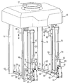
- the figure shows a perspective view of a stack gripper according to the invention.
- the stack gripper consists of an upper part 10, on the top of which a circular flange 12 is attached is to attach the stack gripper to a robot arm.
- the guides are each designed as L-shaped rails in cross section, which extend vertically from the upper part 10 and that lead the stack at its four corners.
- Friction between stack and guide reduced are achieved on the one hand, Friction between stack and guide reduced.
- the guide rails 14, 16, 18, 20, which is a stack receiving space open at the bottom 22 form, are in the upper part 10 each parallel slidably mounted, so that on the one hand Format adjustment can take place and on the other hand the stack receiving space expanded to insert a stack and after Introducing a stack can be reduced.
- the postponement the guide rails are made by parallel guides, that are not shown in detail.
- Stacking support 24, 26 there is one at the lower end of the guide rails Stacking support 24, 26 on which the (not shown) Stack lies flat with its entire length or width.
- the level support of the stack is important because a curved storage of the stack, for example no dimensionally stable discharge of the Stack is possible.
- the main components of pads 24 and 26 are respectively Telescopic cylinder 28, 30, at the front end by means of a bracket a pulley 32, 34 is attached, the around a horizontal and perpendicular to the telescopic cylinder extending axis is rotatable.
- the telescopic cylinders 28, 30 are arranged so that the front End attached pulleys 32, 34 outside the stack receiving space 22 when the cylinders are complete are retracted.
- Telescopic cylinder 28, 30 can be seen, but are in the Practice two parallel telescopic cylinders provided at the front end of each Guide roller 32, 34 is attached.
- the stack supports 24, 26 have in addition to the telescopic cylinders 28, 30 as a further support element, a flexible support tape 36, 38, each guided around a deflection roller 32, 34 is.
- the free end of the respective upper run is on a breakpoint outside the stack receiving space 22 attached.
- the lower run 37, 39 of the support bands is on the underside of the telescopic cylinder 28, 30 from the stack receiving space 22 led out and two more pulleys 40, 42 and 44, 46 out.
- the free end of the lower strand is finally on a bracket 48, 50th fixed in place.
- the deflection rollers 40, 44 are each stationary on the associated guides 18, 20 mounted.
- the deflection rollers 42, 46 are on a rodless cylinder 52, 54 attached, which is parallel to the associated guide rails 18, 20 runs and is attached to this.
- a vertical upward movement of the carriage 51, 53 is thus the lower run 37, 39 of the support bands 36, 38 from the Stack receiving space 22 removed, provided that at the same time Telescopic cylinder 28, 30 (for example by venting) be retracted.
- a Hold-down device 56, 58 arranged, which is rod-shaped and is bent outwards so that the system is as close as possible at the edges of the stack. This will be a prevents the side of the stack from fanning out. Every hold-down is attached to a carriage 60 which by means of a linear cylinder within the stack receiving space 22 parallel to the respective guide rail 18, 20 can be moved up and down.
- a recess 62 is provided, two each Align recesses with each other. Allow these recesses that a device that feeds the stack can also be pulled out of the stack gripper if a very small format is set. For larger ones Formats, the cutouts can also be closed, so that they don't interfere.
- the on a (not shown) Robot arm attached stacking grabs in the area a feed device that pivots the stack (e.g. with a top and a bottom gripper) "reaches".
- the stack gripper according to the invention is so placed in front of the feeder that the reached Stack across the stack supports 24, 26 in the stack receiving space 22 can be introduced. Because the guide rails 14, 16 and 18, 20 are sufficiently spaced that the Stack can be passed between these leaves the stack is contactless in the stack receiving space lead in. After the feeder has stopped the guides 14, 16, 18 and 20 employed, so that the Surround and touch the stack on all sides. Then the Feeder pulled out of the stack gripper be so that the stack with its bottom on the Pads 24 and 26 come to rest. Depending on the the speed of the robot can, however, be the stack gripper also from the top of the stack be lowered.
- the stack gripper After swiveling the robot arm to the desired location on the pallet, the stack gripper with a small Distance to the support surface positioned so that between the moving lower run of the support bands 36, 38 and the contact surface does not come into contact. Subsequently the telescopic cylinders 28 and 30 are vented and at the same time the lifting cylinders 52, 54 become synchronous actuated so that the carriage 51 and 53 upwards move. This movement causes the lower run 37, 39 the support bands 36, 38 on the underside of the actuating cylinder 28, 30 pulled out of the stack receiving space, whereby simultaneously shorten the actuating cylinders 28 and 30. At this process the upper run of the support tapes from the Unrolled the bottom of the stack so that the stack of the Pads 24 and 26 slide, but do not fall.
- each Support tape 36, 38 removed from the stack receiving space 22 and the stack is properly on its base aligned at.
- the stack gripper is then moved upwards raised while the hold-downs move in opposite directions downwards be moved and still press on the top of the stack.
- the hold-down device 56, 58 reaches its lower end position have reached, they operate a signal generator and the Height position value is read out from the robot controller.
- the stack gripper lifts completely the stack and is towards the transfer device moved so that the cycle can start again.
- each carriage 51, 53 by means of a hand lever 64, 66 on an associated guide rod 68, 70 are adjusted so that the support band 36, 38 is excited.
Landscapes
- Engineering & Computer Science (AREA)
- Mechanical Engineering (AREA)
- Pile Receivers (AREA)
- Discharge By Other Means (AREA)
- Load-Engaging Elements For Cranes (AREA)
- Manipulator (AREA)
- Container Filling Or Packaging Operations (AREA)
- Stacking Of Articles And Auxiliary Devices (AREA)
- Fuel Cell (AREA)
- Sheets, Magazines, And Separation Thereof (AREA)
Abstract
Description
Claims (14)
- Stapelgreifer, insbesondere für ungebundene Druckprodukte, miteinem nach unten offenen Stapelaufnahmeraum (22),einer Führung (14, 16, 18, 20), an allen vier Seiten des Stapelaufnahmeraumes, undeiner Stapelauflage (24, 26), auf welcher der Stapel eben und im wesentlichen mit seiner gesamten Länge und/oder Breite aufliegt,
dadurch gekennzeichnet, daßdie Stapelauflage (24, 26) im Bereich des unteren Endes der Führung (14, 16, 18, 20) angeordnet ist, unddie Stapelauflage (24, 26) durch eine Horizontalbewegung aus dem und in den Stapelaufnahmeraum (22) bewegbar ist. - Vorrichtung nach Anspruch 1,
dadurch gekennzeichnet,
daß die Stapelauflage (24, 26) zumindest einen Stellzylinder, vorzugsweise einen Teleskopzylinder (28, 30), oder zumindest eine Schubkette aufweist. - Vorrichtung nach zumindest einem der vorstehenden Ansprüche,
dadurch gekennzeichnet,
daß die Stapelauflage (24, 26) zumindest ein flexibles Auflageband (36, 38) aufweist. - Vorrichtung nach Anspruch 3,
dadurch gekennzeichnet,
daß das Auflageband (36, 38) um eine verschiebbare Umlenkrolle (32, 34) oder eine Gleitführung geführt ist, und daß zum Herausbewegen der Stapelauflage (24, 26) das untere Trum (37, 39) aus dem Stapelaufnahmeraum (22) herausziehbar ist, während das obere Trum zwischen der Umlenkrolle (32, 34) und einem Haltepunkt außerhalb des Stapelaufnahmeraumes (22) gespannt ist. - Vorrichtung nach Anspruch 4,
dadurch gekennzeichnet,
daß das freie Ende des unteren Trums (37, 39) an einem vorzugsweise kolbenstangenlosen Hubzylinder (52, 54) oder einer Schubkette befestigt ist, der bzw. die parallel zu der Führung (18, 20) verfahrbar ist. - Vorrichtung nach Anspruch 4 oder 5,
dadurch gekennzeichnet,
daß der Haltepunkt des oberen Trums bei Herausziehen des unteren Trums (37, 39) um einen vorbestimmten Weg entgegen der Bewegungsrichtung der Stapelauflage (24, 26) verschiebbar ist. - Vorrichtung nach Anspruch 2 und 3 oder 4 - 6,
dadurch gekennzeichnet,
daß das Auflageband (36, 38) um eine Umlenkrolle (32, 34) oder eine Gleitführung geführt ist, die am freien Ende des Stellzylinders (28, 30) oder der Schubkette angeordnet ist. - Vorrichtung nach zumindest einem der vorstehenden Ansprüche,
dadurch gekennzeichnet,
daß innerhalb des Stapelaufnahmeraumes (22) zumindest ein Niederhalter (56, 58) vorgesehen ist, der gegen die Oberseite des Stapels anstellbar ist und der vorzugsweise innerhalb des gesamten Stapelaufnahmeraumes (22) vertikal verstellbar ist. - Vorrichtung nach Anspruch 8,
dadurch gekennzeichnet,
daß mindestens ein Signalgeber vorgesehen ist, der am unteren Endpunkt des Niederhalters (56, 58) angeordnet ist. - Vorrichtung nach zumindest einem der vorstehenden Ansprüche,
dadurch gekennzeichnet,
daß die Führung (14, 16, 18, 20) mit fluchtenden Aussparungen (62) versehen ist, die das Entfernen einer Zuführvorrichtung aus dem Stapelaufnahmeraum (22) ermöglichen. - Vorrichtung nach zumindest einem der vorstehenden Ansprüche,
dadurch gekennzeichnet,
daß insgesamt vier Führungen vorgesehen sind, die über eine Formatverstellung gemeinsam verstellbar sind, und daß an die Formatverstellung ein verschiebbarer Anschlag gekoppelt ist, der die Horizontalbewegung der Stapelauflage (24, 26) entsprechend dem eingestellten Format begrenzt. - Vorrichtung nach Anspruch 11,
dadurch gekennzeichnet,
daß der Anschlag über eine Seilumlenkung mit der Formatverstellung verbunden ist. - Verfahren zum Palettieren mit einem Stapelgreifer nach zumindest einem der Ansprüche 8 - 12,
dadurch gekennzeichnet,
daß der Niederhalter (56, 58) nach unten verschoben wird, während der Stapelgreifer nach oben angehoben wird, so daß ein Druck auf die Oberseite des Stapels ausgeübt wird, vorzugsweise bis der Niederhalter (56, 58) seinen unteren Endpunkt erreicht hat. - Verfahren nach Anspruch 13,
dadurch gekennzeichnet,
daß der Niederhalter (56, 58) an seinem unteren Endpunkt einen Signalgeber auslöst, der vorzugsweise mittels der Robotersteuerung einen Höhenmeßwert erzeugt.
Applications Claiming Priority (2)
| Application Number | Priority Date | Filing Date | Title |
|---|---|---|---|
| DE19626802 | 1996-07-03 | ||
| DE19626802A DE19626802A1 (de) | 1996-07-03 | 1996-07-03 | Stapelgreifer |
Publications (2)
| Publication Number | Publication Date |
|---|---|
| EP0816272A1 true EP0816272A1 (de) | 1998-01-07 |
| EP0816272B1 EP0816272B1 (de) | 2002-03-20 |
Family
ID=7798822
Family Applications (1)
| Application Number | Title | Priority Date | Filing Date |
|---|---|---|---|
| EP97109230A Expired - Lifetime EP0816272B1 (de) | 1996-07-03 | 1997-06-06 | Stapelgreifer |
Country Status (6)
| Country | Link |
|---|---|
| US (1) | US6129504A (de) |
| EP (1) | EP0816272B1 (de) |
| JP (1) | JPH1081421A (de) |
| AT (1) | ATE214680T1 (de) |
| DE (2) | DE19626802A1 (de) |
| DK (1) | DK0816272T3 (de) |
Cited By (7)
| Publication number | Priority date | Publication date | Assignee | Title |
|---|---|---|---|---|
| EP2072430A1 (de) | 2007-12-20 | 2009-06-24 | Müller Martini Holding AG | Paketgreifer für eine Palettiervorrichtung und Verfahren zum Palettieren von Paketen |
| WO2010047595A1 (en) * | 2008-10-23 | 2010-04-29 | Rsw Ip Bv | Palletizer |
| CN104128923A (zh) * | 2013-05-03 | 2014-11-05 | 宁波如意股份有限公司 | 一种机械手专用的手动托盘车车架柔性搬运装置 |
| US9764909B2 (en) | 2010-11-05 | 2017-09-19 | Grenzebach Maschinenbau Gmbh | Device and method for quickly grouping picked goods for transport |
| CN111115241A (zh) * | 2018-08-31 | 2020-05-08 | 南京涵铭置智能科技有限公司 | 一种用于智能制造的盒体取放机械手 |
| AT16811U1 (de) * | 2017-07-20 | 2020-09-15 | Rudholzer Tech Gmbh | Packeinrichtung mit verstellbarer grösse |
| CN120394864A (zh) * | 2025-07-02 | 2025-08-01 | 杭州萧山江南粉末冶金厂 | 一种高效粉末冶金制品摆盘机 |
Families Citing this family (10)
| Publication number | Priority date | Publication date | Assignee | Title |
|---|---|---|---|---|
| US6871893B2 (en) | 2001-11-14 | 2005-03-29 | Gammerler Corporation | Apparatus and method for carrying signature bundles |
| DE102005060946A1 (de) | 2005-12-20 | 2007-06-28 | Gämmerler AG | Stapelgreifer |
| EP2039632B1 (de) | 2007-09-13 | 2010-03-03 | Multivac Sepp Haggenmüller GmbH & Co. KG | Vorrichtung zur Aufnahme und zum Transport eines Gutes |
| US20110076126A1 (en) * | 2009-09-30 | 2011-03-31 | Top Tier, Inc. | Device and Method for Palletizing Items |
| JP2013122489A (ja) | 2011-11-09 | 2013-06-20 | Canon Inc | カートリッジ及びユニット |
| CN108081295B (zh) * | 2018-01-31 | 2023-11-07 | 青岛宝佳智能装备股份有限公司 | 用于不规则固体胶状块形物料搬运的机器人末端执行器 |
| EP3736235B1 (de) * | 2019-05-07 | 2021-03-31 | MBO Postpress Solutions GmbH | Handhabungsvorrichtung für stapel von falzprodukten, entsprechende falzmaschine, und verfahren zum übergeben von stapeln von produkten |
| CN112009922B (zh) * | 2019-05-31 | 2025-03-18 | 河南许继仪表有限公司 | 柱状物料提取装置 |
| DE102023127730A1 (de) * | 2023-10-11 | 2025-04-17 | Multivac Sepp Haggenmüller Se & Co. Kg | Greiferanordnung mit hintereinanderliegenden Produktaufnahmen |
| DE102023133198A1 (de) | 2023-11-28 | 2024-11-07 | Heidelberger Druckmaschinen Aktiengesellschaft | Vorrichtung zum Anheben und Bewegen eines Stapels übereinander liegender flacher Produkte |
Citations (3)
| Publication number | Priority date | Publication date | Assignee | Title |
|---|---|---|---|---|
| EP0359299A2 (de) * | 1988-09-02 | 1990-03-21 | AB Tetra Pak | Automatische Zufuhr- und Beladevorrichtung für bogenförmige Gegenstände |
| EP0377399A1 (de) * | 1988-12-31 | 1990-07-11 | System Gmbh | Greifvorrichtung |
| WO1995029865A1 (en) * | 1994-04-29 | 1995-11-09 | Roll Systems, Inc. | Method and apparatus for business forms processing |
Family Cites Families (13)
| Publication number | Priority date | Publication date | Assignee | Title |
|---|---|---|---|---|
| FR2104713B1 (de) * | 1970-08-21 | 1974-06-14 | Usinor | |
| DE2224280A1 (de) * | 1972-05-18 | 1973-12-06 | Hick & Co Gmbh Maschinenfabrik | Verfahren zum aufeinanderschichten von kisten, kartons od. dgl. in form eines stapelblockes auf einer palette und eine einrichtung zur durchfuehrung des verfahrens |
| SE421781B (sv) * | 1980-01-28 | 1982-02-01 | Wamac Machinery Ab | Anordning vid en maskin serskilt avsedd for lastning av losa tidningsbuntar pa en lastpall |
| DE3024133A1 (de) * | 1980-06-27 | 1982-01-21 | Bilsing, Anton, 5952 Attendorn | Foerder- und/oder stapelvorrichtung |
| DE3024112A1 (de) * | 1980-06-27 | 1982-02-04 | Pfaff Industriemaschinen Gmbh, 6750 Kaiserslautern | Einrichtung zum handhaben von stapeln flexibler gegenstaende, z.b. zeitschriften |
| DE3046280A1 (de) * | 1980-12-09 | 1982-06-09 | Windmöller & Hölscher, 4540 Lengerich | Vorrichtung zum einlegen von schlauchstueckpaketen in das stapelmagazin eines rotationsanlegers |
| DD205146B1 (de) * | 1982-05-17 | 1986-10-22 | Veg Obstproduktion Borthen | Vorrichtung zum palettieren quaderfoermiger gueter, insbesondere von obststeigen |
| IT8522218V0 (it) * | 1985-06-19 | 1985-06-19 | Ottavio Conterno | Palettizzatore automatico. |
| DE3527902A1 (de) * | 1985-08-03 | 1987-02-12 | Mohndruck Reinhard Mohn Ohg | Vorrichtung und verfahren zum stapeln und/oder palettieren von insbesondere duennen produkten eines druckereibetriebes |
| FR2619094B1 (fr) * | 1987-08-05 | 1989-12-15 | Bobst Sa | Dispositif d'empilage d'objets plats disposes en paquets |
| US5141274A (en) * | 1988-02-09 | 1992-08-25 | Galpin Research, Limited Partnership | Apparatus for grasping and handling cubes of stacked printed products |
| DE4203118C2 (de) * | 1991-11-07 | 2003-06-12 | Windmoeller & Hoelscher | Vorrichtung zum Ergreifen und Transportieren von Stapeln flacher Gegenstände |
| DE9418577U1 (de) * | 1994-11-22 | 1995-01-05 | Icoma Packtechnik Gmbh, 77855 Achern | Palettiervorrichtung |
-
1996
- 1996-07-03 DE DE19626802A patent/DE19626802A1/de not_active Withdrawn
-
1997
- 1997-06-06 AT AT97109230T patent/ATE214680T1/de active
- 1997-06-06 EP EP97109230A patent/EP0816272B1/de not_active Expired - Lifetime
- 1997-06-06 DK DK97109230T patent/DK0816272T3/da active
- 1997-06-06 DE DE59706651T patent/DE59706651D1/de not_active Expired - Lifetime
- 1997-07-02 US US08/887,097 patent/US6129504A/en not_active Expired - Lifetime
- 1997-07-03 JP JP9178493A patent/JPH1081421A/ja active Pending
Patent Citations (3)
| Publication number | Priority date | Publication date | Assignee | Title |
|---|---|---|---|---|
| EP0359299A2 (de) * | 1988-09-02 | 1990-03-21 | AB Tetra Pak | Automatische Zufuhr- und Beladevorrichtung für bogenförmige Gegenstände |
| EP0377399A1 (de) * | 1988-12-31 | 1990-07-11 | System Gmbh | Greifvorrichtung |
| WO1995029865A1 (en) * | 1994-04-29 | 1995-11-09 | Roll Systems, Inc. | Method and apparatus for business forms processing |
Cited By (11)
| Publication number | Priority date | Publication date | Assignee | Title |
|---|---|---|---|---|
| EP2072430A1 (de) | 2007-12-20 | 2009-06-24 | Müller Martini Holding AG | Paketgreifer für eine Palettiervorrichtung und Verfahren zum Palettieren von Paketen |
| US8235436B2 (en) | 2007-12-20 | 2012-08-07 | Mueller Martini Holding Ag | Bundle gripper for a palletizing machine and method for the palletizing of bundles |
| WO2010047595A1 (en) * | 2008-10-23 | 2010-04-29 | Rsw Ip Bv | Palletizer |
| US8622685B2 (en) | 2008-10-23 | 2014-01-07 | Rsw Ip Bv | Apparatus and method for stacking objects |
| US9764909B2 (en) | 2010-11-05 | 2017-09-19 | Grenzebach Maschinenbau Gmbh | Device and method for quickly grouping picked goods for transport |
| CN104128923A (zh) * | 2013-05-03 | 2014-11-05 | 宁波如意股份有限公司 | 一种机械手专用的手动托盘车车架柔性搬运装置 |
| CN104128923B (zh) * | 2013-05-03 | 2016-02-17 | 宁波如意股份有限公司 | 一种机械手专用的手动托盘车车架柔性搬运装置 |
| AT16811U1 (de) * | 2017-07-20 | 2020-09-15 | Rudholzer Tech Gmbh | Packeinrichtung mit verstellbarer grösse |
| CN111115241A (zh) * | 2018-08-31 | 2020-05-08 | 南京涵铭置智能科技有限公司 | 一种用于智能制造的盒体取放机械手 |
| CN111115241B (zh) * | 2018-08-31 | 2021-06-11 | 南京涵铭置智能科技有限公司 | 一种用于智能制造的盒体取放机械手 |
| CN120394864A (zh) * | 2025-07-02 | 2025-08-01 | 杭州萧山江南粉末冶金厂 | 一种高效粉末冶金制品摆盘机 |
Also Published As
| Publication number | Publication date |
|---|---|
| JPH1081421A (ja) | 1998-03-31 |
| DE19626802A1 (de) | 1998-01-08 |
| DK0816272T3 (da) | 2002-05-27 |
| US6129504A (en) | 2000-10-10 |
| EP0816272B1 (de) | 2002-03-20 |
| DE59706651D1 (de) | 2002-04-25 |
| ATE214680T1 (de) | 2002-04-15 |
Similar Documents
| Publication | Publication Date | Title |
|---|---|---|
| EP0816272B1 (de) | Stapelgreifer | |
| EP0423065A2 (de) | Entstapelgerät zum Abnehmen eines Teilstapels von einem Blätterstapel | |
| DE3937995C2 (de) | Verfahren und Vorrichtung zur Bogenriesvereinzelung und zur Riesablage | |
| DE2551252C2 (de) | Rückstapelgerät zum Stapeln von Blattmaterial-Teilstapeln zu einem Gesamtstapel | |
| DE2516957B2 (de) | Vorrichtung zum selbsttätigen Beladen von ortsfesten oder ortsbeweglichen Ladeflächen mit Stückgütern, insbesondere Säcken, im Verband | |
| DE69128660T2 (de) | Einrichtung zum Sortieren von kleinen, aus Blechen gestanzten Werkstücken | |
| DE4401818C2 (de) | Klemmeinrichtung, insbesondere zum Einklemmen eines Bogenpakets beim Stapelwechsel in Stapelvorrichtungen für Papier- oder Kartonbögen | |
| DE4008592A1 (de) | Vorrichtung zum automatischen Zu- und Abführen von Platten aus Karton, Wellpappe und dergl., zu einer Stanz- und/oder Druckmaschine | |
| DD281369A5 (de) | Ueberleitvorrichtung fuer baender zwischen einer ablaufhaspel und einer bandbe- oder bandverarbeitungseinrichtung | |
| DE2634634A1 (de) | Stapel- und einfuellvorrichtung fuer bahnteile aus kompressiblem material | |
| DE3881374T2 (de) | Stossabsorbierender Werkstückträger für Biegemaschinen. | |
| DE3539099A1 (de) | Vorrichtung zum einbringen von markierungsstreifen in bogenstapel | |
| EP0481323B1 (de) | Verfahren zum Beschicken einer Bearbeitungsmaschine mit einem Feinzentrierschritt und Vorrichtung hierfür | |
| EP0773179A2 (de) | Einrichtung zur Hilfsstapelbildung beim Nonstopstapelwechsel im Ausleger einer Druckmaschine | |
| DE3024133A1 (de) | Foerder- und/oder stapelvorrichtung | |
| EP3360807B1 (de) | Umreifungsvorrichtung zum umreifen eines packguts | |
| EP0751086B1 (de) | Vorrichtung zum Entfernen von Lufteinschlüssen aus Papierstapeln | |
| DE4139978C1 (de) | ||
| EP0612682B1 (de) | Vorrichtung zum Ansammeln von Papierbogen | |
| DE9004711U1 (de) | Rütteltisch für blattförmiges Gut | |
| DE10141964B4 (de) | Verfahren und Vorrichtung zum Stapeln von Riesen | |
| EP0748290B1 (de) | Vorrichtung zum stapeln von bögen | |
| DE3638970C2 (de) | ||
| EP1264794B1 (de) | Verfahren und Vorrichtung zum Ansammeln von Bogen zu Stapeln an einer Stapelablage | |
| DE19821918B4 (de) | Verfahren zum Fördern von Produkten und Handhabungseinheit zur Durchführung des Verfahrens |
Legal Events
| Date | Code | Title | Description |
|---|---|---|---|
| PUAI | Public reference made under article 153(3) epc to a published international application that has entered the european phase |
Free format text: ORIGINAL CODE: 0009012 |
|
| AK | Designated contracting states |
Kind code of ref document: A1 Designated state(s): AT BE CH DE DK FR GB IT LI NL |
|
| 17P | Request for examination filed |
Effective date: 19980202 |
|
| AKX | Designation fees paid |
Free format text: AT BE CH DE DK FR GB IT LI NL |
|
| RBV | Designated contracting states (corrected) |
Designated state(s): AT BE CH DE DK FR GB IT LI NL |
|
| 17Q | First examination report despatched |
Effective date: 19991227 |
|
| GRAG | Despatch of communication of intention to grant |
Free format text: ORIGINAL CODE: EPIDOS AGRA |
|
| GRAG | Despatch of communication of intention to grant |
Free format text: ORIGINAL CODE: EPIDOS AGRA |
|
| GRAH | Despatch of communication of intention to grant a patent |
Free format text: ORIGINAL CODE: EPIDOS IGRA |
|
| GRAH | Despatch of communication of intention to grant a patent |
Free format text: ORIGINAL CODE: EPIDOS IGRA |
|
| REG | Reference to a national code |
Ref country code: GB Ref legal event code: IF02 |
|
| RAP1 | Party data changed (applicant data changed or rights of an application transferred) |
Owner name: GAEMMERLER AG |
|
| GRAA | (expected) grant |
Free format text: ORIGINAL CODE: 0009210 |
|
| AK | Designated contracting states |
Kind code of ref document: B1 Designated state(s): AT BE CH DE DK FR GB IT LI NL |
|
| REF | Corresponds to: |
Ref document number: 214680 Country of ref document: AT Date of ref document: 20020415 Kind code of ref document: T |
|
| REG | Reference to a national code |
Ref country code: CH Ref legal event code: EP |
|
| REF | Corresponds to: |
Ref document number: 59706651 Country of ref document: DE Date of ref document: 20020425 |
|
| REG | Reference to a national code |
Ref country code: DK Ref legal event code: T3 |
|
| ET | Fr: translation filed | ||
| GBT | Gb: translation of ep patent filed (gb section 77(6)(a)/1977) |
Effective date: 20020523 |
|
| PLBE | No opposition filed within time limit |
Free format text: ORIGINAL CODE: 0009261 |
|
| STAA | Information on the status of an ep patent application or granted ep patent |
Free format text: STATUS: NO OPPOSITION FILED WITHIN TIME LIMIT |
|
| 26N | No opposition filed |
Effective date: 20021223 |
|
| PGFP | Annual fee paid to national office [announced via postgrant information from national office to epo] |
Ref country code: CH Payment date: 20110623 Year of fee payment: 15 Ref country code: FR Payment date: 20110630 Year of fee payment: 15 |
|
| PGFP | Annual fee paid to national office [announced via postgrant information from national office to epo] |
Ref country code: GB Payment date: 20110620 Year of fee payment: 15 Ref country code: DK Payment date: 20110610 Year of fee payment: 15 Ref country code: AT Payment date: 20110613 Year of fee payment: 15 Ref country code: NL Payment date: 20110621 Year of fee payment: 15 |
|
| PGFP | Annual fee paid to national office [announced via postgrant information from national office to epo] |
Ref country code: BE Payment date: 20110614 Year of fee payment: 15 |
|
| PGFP | Annual fee paid to national office [announced via postgrant information from national office to epo] |
Ref country code: IT Payment date: 20110625 Year of fee payment: 15 |
|
| BERE | Be: lapsed |
Owner name: *GAMMERLER A.G. Effective date: 20120630 |
|
| REG | Reference to a national code |
Ref country code: NL Ref legal event code: V1 Effective date: 20130101 |
|
| REG | Reference to a national code |
Ref country code: DK Ref legal event code: EBP |
|
| REG | Reference to a national code |
Ref country code: CH Ref legal event code: PL |
|
| REG | Reference to a national code |
Ref country code: CH Ref legal event code: PL Ref country code: AT Ref legal event code: MM01 Ref document number: 214680 Country of ref document: AT Kind code of ref document: T Effective date: 20120606 |
|
| GBPC | Gb: european patent ceased through non-payment of renewal fee |
Effective date: 20120606 |
|
| PG25 | Lapsed in a contracting state [announced via postgrant information from national office to epo] |
Ref country code: IT Free format text: LAPSE BECAUSE OF NON-PAYMENT OF DUE FEES Effective date: 20120606 |
|
| REG | Reference to a national code |
Ref country code: FR Ref legal event code: ST Effective date: 20130228 |
|
| PG25 | Lapsed in a contracting state [announced via postgrant information from national office to epo] |
Ref country code: GB Free format text: LAPSE BECAUSE OF NON-PAYMENT OF DUE FEES Effective date: 20120606 Ref country code: NL Free format text: LAPSE BECAUSE OF NON-PAYMENT OF DUE FEES Effective date: 20130101 Ref country code: CH Free format text: LAPSE BECAUSE OF NON-PAYMENT OF DUE FEES Effective date: 20120630 Ref country code: FR Free format text: LAPSE BECAUSE OF NON-PAYMENT OF DUE FEES Effective date: 20120702 Ref country code: LI Free format text: LAPSE BECAUSE OF NON-PAYMENT OF DUE FEES Effective date: 20120630 Ref country code: BE Free format text: LAPSE BECAUSE OF NON-PAYMENT OF DUE FEES Effective date: 20120630 |
|
| PG25 | Lapsed in a contracting state [announced via postgrant information from national office to epo] |
Ref country code: AT Free format text: LAPSE BECAUSE OF NON-PAYMENT OF DUE FEES Effective date: 20120606 |
|
| PG25 | Lapsed in a contracting state [announced via postgrant information from national office to epo] |
Ref country code: DK Free format text: LAPSE BECAUSE OF NON-PAYMENT OF DUE FEES Effective date: 20120702 |
|
| PGFP | Annual fee paid to national office [announced via postgrant information from national office to epo] |
Ref country code: DE Payment date: 20140829 Year of fee payment: 18 |
|
| REG | Reference to a national code |
Ref country code: DE Ref legal event code: R119 Ref document number: 59706651 Country of ref document: DE |
|
| PG25 | Lapsed in a contracting state [announced via postgrant information from national office to epo] |
Ref country code: DE Free format text: LAPSE BECAUSE OF NON-PAYMENT OF DUE FEES Effective date: 20160101 |