EP0816526A2 - Isolierendes, wärmedämmendes Beschichtungssystem - Google Patents
Isolierendes, wärmedämmendes Beschichtungssystem Download PDFInfo
- Publication number
- EP0816526A2 EP0816526A2 EP97304676A EP97304676A EP0816526A2 EP 0816526 A2 EP0816526 A2 EP 0816526A2 EP 97304676 A EP97304676 A EP 97304676A EP 97304676 A EP97304676 A EP 97304676A EP 0816526 A2 EP0816526 A2 EP 0816526A2
- Authority
- EP
- European Patent Office
- Prior art keywords
- bond coat
- metallic
- substrate
- insulating layer
- porous ceramic
- Prior art date
- Legal status (The legal status is an assumption and is not a legal conclusion. Google has not performed a legal analysis and makes no representation as to the accuracy of the status listed.)
- Granted
Links
- 239000012720 thermal barrier coating Substances 0.000 title claims abstract description 34
- 239000000758 substrate Substances 0.000 claims abstract description 54
- 239000000919 ceramic Substances 0.000 claims abstract description 35
- 238000010438 heat treatment Methods 0.000 claims abstract description 28
- MCMNRKCIXSYSNV-UHFFFAOYSA-N Zirconium dioxide Chemical compound O=[Zr]=O MCMNRKCIXSYSNV-UHFFFAOYSA-N 0.000 claims description 32
- PXHVJJICTQNCMI-UHFFFAOYSA-N nickel Substances [Ni] PXHVJJICTQNCMI-UHFFFAOYSA-N 0.000 claims description 22
- 238000000034 method Methods 0.000 claims description 17
- 239000000463 material Substances 0.000 claims description 15
- RUDFQVOCFDJEEF-UHFFFAOYSA-N yttrium(III) oxide Inorganic materials [O-2].[O-2].[O-2].[Y+3].[Y+3] RUDFQVOCFDJEEF-UHFFFAOYSA-N 0.000 claims description 14
- 229920000728 polyester Polymers 0.000 claims description 8
- 238000000151 deposition Methods 0.000 claims description 7
- 239000000203 mixture Substances 0.000 claims description 7
- 229910052759 nickel Inorganic materials 0.000 claims description 6
- 229910000601 superalloy Inorganic materials 0.000 claims description 5
- 238000005422 blasting Methods 0.000 claims description 4
- CETPSERCERDGAM-UHFFFAOYSA-N ceric oxide Chemical compound O=[Ce]=O CETPSERCERDGAM-UHFFFAOYSA-N 0.000 claims description 4
- 229910000422 cerium(IV) oxide Inorganic materials 0.000 claims description 4
- 229910017052 cobalt Inorganic materials 0.000 claims description 4
- 239000010941 cobalt Substances 0.000 claims description 4
- GUTLYIVDDKVIGB-UHFFFAOYSA-N cobalt atom Chemical compound [Co] GUTLYIVDDKVIGB-UHFFFAOYSA-N 0.000 claims description 4
- 239000000446 fuel Substances 0.000 claims description 4
- 238000000541 cathodic arc deposition Methods 0.000 claims description 2
- 238000005507 spraying Methods 0.000 claims description 2
- 239000007921 spray Substances 0.000 claims 1
- 238000000576 coating method Methods 0.000 abstract description 16
- 239000011248 coating agent Substances 0.000 abstract description 14
- 238000009413 insulation Methods 0.000 abstract description 3
- 229910010293 ceramic material Inorganic materials 0.000 description 17
- 230000003647 oxidation Effects 0.000 description 14
- 238000007254 oxidation reaction Methods 0.000 description 14
- 239000000956 alloy Substances 0.000 description 7
- 239000010410 layer Substances 0.000 description 7
- 239000002245 particle Substances 0.000 description 7
- 239000000843 powder Substances 0.000 description 7
- 229910045601 alloy Inorganic materials 0.000 description 6
- 230000008901 benefit Effects 0.000 description 5
- 238000004140 cleaning Methods 0.000 description 3
- 238000005524 ceramic coating Methods 0.000 description 2
- 239000011651 chromium Substances 0.000 description 2
- 238000005336 cracking Methods 0.000 description 2
- 238000009792 diffusion process Methods 0.000 description 2
- 238000010348 incorporation Methods 0.000 description 2
- 238000007689 inspection Methods 0.000 description 2
- TWNQGVIAIRXVLR-UHFFFAOYSA-N oxo(oxoalumanyloxy)alumane Chemical compound O=[Al]O[Al]=O TWNQGVIAIRXVLR-UHFFFAOYSA-N 0.000 description 2
- 238000007750 plasma spraying Methods 0.000 description 2
- 230000003068 static effect Effects 0.000 description 2
- 238000011179 visual inspection Methods 0.000 description 2
- 229910001247 waspaloy Inorganic materials 0.000 description 2
- 229910052727 yttrium Inorganic materials 0.000 description 2
- VWQVUPCCIRVNHF-UHFFFAOYSA-N yttrium atom Chemical compound [Y] VWQVUPCCIRVNHF-UHFFFAOYSA-N 0.000 description 2
- OYPRJOBELJOOCE-UHFFFAOYSA-N Calcium Chemical compound [Ca] OYPRJOBELJOOCE-UHFFFAOYSA-N 0.000 description 1
- VYZAMTAEIAYCRO-UHFFFAOYSA-N Chromium Chemical compound [Cr] VYZAMTAEIAYCRO-UHFFFAOYSA-N 0.000 description 1
- 241001147665 Foraminifera Species 0.000 description 1
- FYYHWMGAXLPEAU-UHFFFAOYSA-N Magnesium Chemical compound [Mg] FYYHWMGAXLPEAU-UHFFFAOYSA-N 0.000 description 1
- NINIDFKCEFEMDL-UHFFFAOYSA-N Sulfur Chemical group [S] NINIDFKCEFEMDL-UHFFFAOYSA-N 0.000 description 1
- 230000001464 adherent effect Effects 0.000 description 1
- 229910052782 aluminium Inorganic materials 0.000 description 1
- XAGFODPZIPBFFR-UHFFFAOYSA-N aluminium Chemical compound [Al] XAGFODPZIPBFFR-UHFFFAOYSA-N 0.000 description 1
- 229910052791 calcium Inorganic materials 0.000 description 1
- 239000011575 calcium Substances 0.000 description 1
- 230000015556 catabolic process Effects 0.000 description 1
- 229910052804 chromium Inorganic materials 0.000 description 1
- 238000002485 combustion reaction Methods 0.000 description 1
- 230000001143 conditioned effect Effects 0.000 description 1
- 238000011109 contamination Methods 0.000 description 1
- 238000006731 degradation reaction Methods 0.000 description 1
- 230000008030 elimination Effects 0.000 description 1
- 238000003379 elimination reaction Methods 0.000 description 1
- 230000003628 erosive effect Effects 0.000 description 1
- 230000010006 flight Effects 0.000 description 1
- -1 for example Substances 0.000 description 1
- 239000011810 insulating material Substances 0.000 description 1
- 239000011229 interlayer Substances 0.000 description 1
- 230000000670 limiting effect Effects 0.000 description 1
- 238000003754 machining Methods 0.000 description 1
- 229910052749 magnesium Inorganic materials 0.000 description 1
- 239000011777 magnesium Substances 0.000 description 1
- 229910052751 metal Inorganic materials 0.000 description 1
- 239000002184 metal Substances 0.000 description 1
- 230000001590 oxidative effect Effects 0.000 description 1
- 238000002360 preparation method Methods 0.000 description 1
- 239000011253 protective coating Substances 0.000 description 1
- 230000002829 reductive effect Effects 0.000 description 1
- 239000011593 sulfur Substances 0.000 description 1
- 229910052717 sulfur Inorganic materials 0.000 description 1
- 238000012876 topography Methods 0.000 description 1
Images


Classifications
-
- C—CHEMISTRY; METALLURGY
- C23—COATING METALLIC MATERIAL; COATING MATERIAL WITH METALLIC MATERIAL; CHEMICAL SURFACE TREATMENT; DIFFUSION TREATMENT OF METALLIC MATERIAL; COATING BY VACUUM EVAPORATION, BY SPUTTERING, BY ION IMPLANTATION OR BY CHEMICAL VAPOUR DEPOSITION, IN GENERAL; INHIBITING CORROSION OF METALLIC MATERIAL OR INCRUSTATION IN GENERAL
- C23C—COATING METALLIC MATERIAL; COATING MATERIAL WITH METALLIC MATERIAL; SURFACE TREATMENT OF METALLIC MATERIAL BY DIFFUSION INTO THE SURFACE, BY CHEMICAL CONVERSION OR SUBSTITUTION; COATING BY VACUUM EVAPORATION, BY SPUTTERING, BY ION IMPLANTATION OR BY CHEMICAL VAPOUR DEPOSITION, IN GENERAL
- C23C4/00—Coating by spraying the coating material in the molten state, e.g. by flame, plasma or electric discharge
- C23C4/02—Pretreatment of the material to be coated, e.g. for coating on selected surface areas
-
- Y—GENERAL TAGGING OF NEW TECHNOLOGICAL DEVELOPMENTS; GENERAL TAGGING OF CROSS-SECTIONAL TECHNOLOGIES SPANNING OVER SEVERAL SECTIONS OF THE IPC; TECHNICAL SUBJECTS COVERED BY FORMER USPC CROSS-REFERENCE ART COLLECTIONS [XRACs] AND DIGESTS
- Y02—TECHNOLOGIES OR APPLICATIONS FOR MITIGATION OR ADAPTATION AGAINST CLIMATE CHANGE
- Y02T—CLIMATE CHANGE MITIGATION TECHNOLOGIES RELATED TO TRANSPORTATION
- Y02T50/00—Aeronautics or air transport
- Y02T50/60—Efficient propulsion technologies, e.g. for aircraft
Definitions
- This invention relates to ceramic thermal barrier coating systems used to insulate substrates from elevated temperatures.
- Modern gas turbine engines particularly those used in aircraft, operate at high rotational speeds and high temperatures for increased performance and efficiency. There is a high demand for improved performance and efficiency because of the desire to increase the range an aircraft can fly without stopping to refuel.
- Ceramic thermal barrier coating system applications include a metallic bond coat which requires a bond coat adherence high temperature heat treatment to maximize the strength of the bond between the substrate and the metallic bond coat. While the bond coat adherence heat treatment is conventionally applied after application of the ceramic material, it could be performed prior to depositing the ceramic material.
- An exemplary bond coat adherence high temperature heat treatment includes heating a ceramic coated substrate in a nonoxidizing environment for one to ten hours at 1800°F (982°C) to 2050°F (1121°C).
- thermal barrier coating system requiring no bond coat adherence high temperature heat treatment and having enhanced insulating capabilities such that it may be applied to gas turbine engine components of varied shape, thickness and size.
- an insulating thermal barrier coating system for a metallic substrate comprises a metallic bond coat receiving no bond coat adherence high temperature heat treatment to form a bond between the metallic bond coat and the metallic substrate to which the metallic bond coat is applied; and a porous ceramic insulating layer deposited on the metallic bond coat.
- the insulating thermal barrier coating system comprises a metallic bond coat consisting substantially of, in weight percent, 15-40Co, 10-40Cr, 6-15Al, 0-0.7Si, 0-2.0Hf, 0.01-1.0Y, balance Ni.
- the metallic bond coat received no bond coat adherence high temperature heat treatment to form a bond between the metallic bond coat and the metallic substrate to which the metallic bond coat is applied.
- the coating system also comprises a porous ceramic insulating layer on the bond coat.
- the porous ceramic insulating layer comprises zirconia partially stabilized with about 6-8 weight percent yttria, and has a porosity between about 20-35 volume percent and a thickness between about 25-50 mils (0.635-1.27 mm). Porosity is intentionally created within the ceramic insulating layer by incorporating a small amount of polyester powder within the ceramic material.
- the invention also extends in broad terms to a metallic substrate thermally insulated with a porous ceramic insulating layer comprising, in weight percent, zirconia partially stabilized with about 6-8 yttria and having a porosity between about 20-35 volume percent.
- an insulating thermal barrier coating system is applied to a metallic substrate.
- the substrate may be made of a conventional nickel base or cobalt base superalloy material and may be cast and machined to desired final shape/size using known techniques.
- the substrate Prior to applying the insulating thermal barrier coating system to the substrate, the substrate is prepared to receive the coating system. Preparation is conventional and includes cleaning the substrate surface to remove contamination. Suitable cleaning methods include, but are not limited to, aluminum oxide grit blasting. Preferably, the surface is roughened by the cleaning process to aid the adherence of the subsequently applied bond coat to the substrate.
- a metallic bond coat requiring no bond coat adherence high temperature heat treatment is then applied to the substrate.
- a preferred feature of the present invention is use of a metallic bond coat receiving no such high temperature or diffusion heat treatment.
- the invention is particularly advantageous for insulating metallic components prone to distortion during heat treatment or those requiring insulation in an as machined condition.
- the invention is also particularly advantageous for insulating materials whose properties may not be capable of withstanding exposure to such a high temperature heat treatment without, for example, losing strength or oxidizing.
- the invention is advantageous for insulating metallic components which are intolerant of high temperature bond coat diffusion heat treatment cycles.
- the invention has particular utility in insulating static gas turbine engine components, such as turbine vanes and turbine vane supports, because these components do not undergo the centrifugal forces as do turbine blades.
- Yet another significant advantage is the cost savings associated with eliminating a subsequent heat treatment step.
- a metallic bond coat of a NiCoCrAlY material is employed, particularly if oxidation resistance is desired.
- Ni denotes nickel
- Co denotes cobalt
- Cr denotes chromium
- Al denotes aluminum
- Y denotes yttrium.
- the bond coat material has a composition falling within the broad weight percent range of 15-40Co, 10-40Cr, 6-15Al, 0-.7Si, 0-2.0Hf, 0.01-1.0Y, balance essentially Ni.
- the bond coat material has a composition falling within the weight percent range of 20-26Co, 15-19Cr, 11.5-13.5Al, 0-.7Si, 0-2.0Hf, 0.20-0.70Y, balance essentially Ni.
- the particle size ofthe bond coat material is preferably within the range -170+325 US std. sieve (44 to 88pm).
- the bond coat thickness may be between about 0.001-0.015 inches (0.076-0.381 mm). Preferably the thickness ofthe bond coat is between about 0.005-0.009 inches (0.127-0.229 mm).
- the bond coat is preferably plasma sprayed, in air, on the surface of the substrate to be protected. Other deposition techniques, including but not limited to, high velocity oxy fuel (HVOF) spraying or cathodic arc deposition may be employed.
- HVOF high velocity oxy fuel
- the surface topography of the bond coat is such that it is suitable to receive the subsequently applied ceramic material.
- the metallic bond coat is plasma sprayed, in air, which will yield a roughened bond coat surface.
- a porous ceramic material comprising zirconia partially stabilized with 6 to 8 percent (by weight) yttria is then applied.
- the ceramic material is preferably plasma sprayed in air and the substrate temperature is maintained at less than 500°F (260°C).
- Other deposition techniques including but not limited to, high velocity oxy fuel (HVOF) may also be employed.
- the ceramic particle size is between about 5 and about 180 microns (.005 and about .18 mm) and preferably about 50 microns (.05 mm) mean diameter.
- Porosity is intentionally created within the ceramic coating.
- porosity is achieved by incorporating between about 1-12 weight percent polyester powder within the ceramic.
- the thickness of the ceramic coating can range from 25 to 50 mils (.635 to 1.27 mm) and preferably from 25 to 35 mils (.635 to .889 mm).
- ceramic materials having low thermal conductivity including but not limited to, zirconia fully stabilized with yttria, zirconia stabilized with ceria, or ceria may be substituted for the above described zirconia partially stabilized with yttria.
- the above described ceramic layer may be deposited directly on the metallic substrate, without the use of a bond coat.
- This embodiment may be feasible for insulation of oxidation resistant alloys, for example, alloys including active elements, such as yttrium, calcium, or magnesium, or alloys made from low sulfur bearing materials, or alloys subsequently desulfurized.
- oxidation resistant alloys for example, alloys including active elements, such as yttrium, calcium, or magnesium, or alloys made from low sulfur bearing materials, or alloys subsequently desulfurized.
- direct bonding of the ceramic layer may also be feasible if the substrate is pre-oxidized in a controlled manner to grow a strongly adherent oxide interlayer.
- this embodiment may be advantageous for static applications in a nonerosive environment or where the substrate temperature can be maintained at less than about 1800°F (982°C).
- Various ceramic thermal barrier coating systems were applied to cast combustor segments.
- the material of each segment was made from the same base alloy having a nominal composition, in weight percent, of 8.0Cr, 10Co, 6.0Mo, 6.0Al, 4.3Ta, 1.15Hf, 1.0Ti, 0.015B, 0.08Zr, balance Ni (B-1900+Hf).
- the test segments occupied portions of rows 2, 3 and 4 on the outer liner ofa gas turbine combustor.
- the liner was then subjected to a severe test employing conditions more demanding than those encountered in normal operation of a gas turbine engine.
- the test included 1300 cycles. The first 300 cycles were run under normal takeoff conditions; 1000 of the cycles included 5.5 minutes at maximum allowable operating temperature which accelerated the oxidation rate per cycle. It should be noted that the combustion process is such that flame conditions in the region of rows 2 and 3 were hotter than that of row 4.
- FIG. 2 depicts the oxidation damage (or lack thereof) of the various segments. Oxidation damage was determined by visually inspecting each segment for any burned/oxidized portions and determining the approximate severity of damage.
- the left-most bar (A) on the chart represents the performance of a coating consisting of zirconia partially stabilized with 6-8 weight percent yttria plasma deposited in air on a NiCoCrAlY bond coat (nominal composition, in weight percent, of 23Co, 17Cr, 12.5Al, 0.45Y, balance Ni) which was also plasma deposited in air.
- the thickness of the bond coat was about 0.007 inches (0.178 mm), and the thickness of the ceramic material was about 0.014 inches (0.356 mm).
- This Sample A was applied to 5 of 10 segments on row 2 of the outer liner. Sample A did not include any intentionally introduced porosity.
- a preferred insulating thermal barrier coating system of the present invention was applied to the remaining 5 segments in row 2 by first plasma spraying, in air, the bond coat.
- the material of the bond coat had nominal composition, in weight percent, of 23Co, 17Cr, 12.5Al, 0.45Y, balance Ni.
- a porous ceramic material comprising zirconia partially stabilized with 6 to 8 weight percent yttria was air plasma sprayed upon the bond coat. Porosity was intentionally created within the ceramic material through the incorporation of about 2.0 weight percent polyester powder (60 micron (.06 mm) nominal particle size).
- the thickness of the bond coat and the ceramic material was substantially the same as that of Sample A.
- the coating of Sample A was also applied to 4 of 7 segments tested on row 3 of the outer liner.
- the preferred insulating thermal barrier coating system of the present invention was applied to the remaining 3 segments tested, as described above except the thickness of the bond coat and the thickness of the ceramic material was increased by a factor of 1.5 each.
- Four (4) out of 4 segments coated with Sample A coating exhibited trailing edge oxidation damage up to 0.40 inches (1.02 mm).
- Zero (0) out of 3 segments coated in accordance with the preferred embodiment of the present invention exhibited trailing edge oxidation.
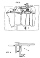
- FIG. 3 schematically illustrates a cross-section of a modern gas turbine engine with a first stage turbine vane support area 10 encircled.
- a preferred insulating thermal barrier coating system 12 of the present invention was applied to the inner diameter surface of a first stage turbine vane support 14, as shown in FIG. 4.
- the substrate material of the first vane support 14 was 19.5Cr, 13.5Co, 4.25Mo, 3.0Ti, 1.4Al, 0.07Zr, 0.007B, balance Ni (AMS 5707 (Waspaloy)).
- the inner diameter of the first stage vane support 14 was cleaned and conditioned by aluminum oxide dry blasting prior to application of the insulating thermal barrier coating system 12.
- the insulating thermal barrier coating system 12 was then applied by first plasma spraying, in air, a preferred bond coat of the present invention to a thickness of about .003 inches (.076 mm).
- the material of the bond coat had nominal composition, in weight percent, of 23Co, 17Cr, 12.5Al, 0.45Y, balance essentially Ni and powder particle sizes within the range -170+325 US std. sieve (44 to 88pm).
- porous ceramic material comprising zirconia partially stabilized with 6 to 8 weight percent yttria was air plasma sprayed upon the bond coat.
- the substrate temperature was maintained at less than 500°F (260°C).
- the size ofthe ceramic powder particles was about 50 microns (.05 mm) in mean diameter. Porosity was intentionally created within the ceramic material through the incorporation of about 2.0 weight percent polyester powder (60 micron (.06 mm) nominal particle size). The thickness of the ceramic material varied between about 25 and 35 mils (.635 and .889 mm).
- the article was then subjected to a 935 cycle engine test simulating flights at various maximum engine power conditions.
- the article exhibited no cracking upon visual inspection as well as upon fluorescent penetrant inspection.
- FIG. 5 further illustrates the significant benefits of the present invention.
- FIG. 5 depicts the life of the first stage turbine vane support 14 with and without a preferred insulating thermal barrier coating system 12 of the present invention versus temperature.
- simulated engine operation at a first stage turbine vane support substrate temperature of approximately 1600°F (871°C) as measured by thermocouples resulted in a predicted life of 2000 cycles for an uncoated first stage turbine vane support (AMS 5707 (Waspaloy)).
- AMS 5707 uncoated first stage turbine vane support
- the significance of operation at 1600°F (871°C) is that this temperature is well above the maximum allowable use temperature for AMS 5707.
- the substrate temperature ofthe first stage turbine vane support 14 was calculated to be reduced to approximately 1450°F (788°C) and an extended predicted life of 19,000 cycles under the same operating conditions was achieved.
- the extension of life by 17,000 cycles illustrates the tremendous insulating benefit of the present invention.
Landscapes
- Chemical & Material Sciences (AREA)
- Engineering & Computer Science (AREA)
- Physics & Mathematics (AREA)
- Plasma & Fusion (AREA)
- Chemical Kinetics & Catalysis (AREA)
- Materials Engineering (AREA)
- Mechanical Engineering (AREA)
- Metallurgy (AREA)
- Organic Chemistry (AREA)
- Turbine Rotor Nozzle Sealing (AREA)
- Other Surface Treatments For Metallic Materials (AREA)
- Coating By Spraying Or Casting (AREA)
Applications Claiming Priority (2)
| Application Number | Priority Date | Filing Date | Title |
|---|---|---|---|
| US67146696A | 1996-06-27 | 1996-06-27 | |
| US671466 | 1996-06-27 |
Publications (3)
| Publication Number | Publication Date |
|---|---|
| EP0816526A2 true EP0816526A2 (de) | 1998-01-07 |
| EP0816526A3 EP0816526A3 (de) | 1998-01-28 |
| EP0816526B1 EP0816526B1 (de) | 2001-10-17 |
Family
ID=24694632
Family Applications (1)
| Application Number | Title | Priority Date | Filing Date |
|---|---|---|---|
| EP97304676A Revoked EP0816526B1 (de) | 1996-06-27 | 1997-06-27 | Isolierendes, wärmedämmendes Beschichtungssystem |
Country Status (3)
| Country | Link |
|---|---|
| EP (1) | EP0816526B1 (de) |
| JP (2) | JP3258599B2 (de) |
| DE (1) | DE69707365T2 (de) |
Cited By (21)
| Publication number | Priority date | Publication date | Assignee | Title |
|---|---|---|---|---|
| WO2000075398A1 (en) * | 1999-06-02 | 2000-12-14 | Abb Research Ltd. | Coating composition for high temperature protection |
| EP1254967A1 (de) * | 2001-04-26 | 2002-11-06 | General Electric Company | Verbessertes plasmagespritztes Wärmedämmhaftungsschichtsystem |
| EP1411210A1 (de) * | 2002-10-15 | 2004-04-21 | ALSTOM Technology Ltd | Verfahren zur Abscheidung einer ermüdungs- und oxydationsbeständigen MCrAlY-Beschichtung |
| US6764779B1 (en) | 2003-02-24 | 2004-07-20 | Chromalloy Gas Turbine Corporation | Thermal barrier coating having low thermal conductivity |
| US6803135B2 (en) | 2003-02-24 | 2004-10-12 | Chromalloy Gas Turbine Corporation | Thermal barrier coating having low thermal conductivity |
| US7041383B2 (en) | 2004-01-12 | 2006-05-09 | Chromalloy Gas Turbine Corporation | Durable thermal barrier coating having low thermal conductivity |
| EP1818419A1 (de) * | 2006-01-16 | 2007-08-15 | Siemens Aktiengesellschaft | Legierung, Schutzschicht und Bauteil |
| WO2008110161A1 (de) * | 2007-03-14 | 2008-09-18 | Fraunhofer-Gesellschaft zur Förderung der angewandten Forschung e.V. | Schichtsystem und verfahren zu dessen herstellung |
| EP2113582A2 (de) | 2008-04-30 | 2009-11-04 | United Technologies Corporation | Verfahren zum Formen einer dicken keramischen Beschichtung mit verbesserter Beständigkeit |
| WO2013107712A1 (de) * | 2012-01-16 | 2013-07-25 | Fraunhofer-Gesellschaft zur Förderung der angewandten Forschung e.V. | Verfahren zur herstellung einer keramischen schicht auf einer aus einer ni-basislegierung gebildeten oberfläche |
| CN104220698A (zh) * | 2012-03-28 | 2014-12-17 | 西门子公司 | 用于制造和重新整修燃气轮机中的陶瓷隔热层的方法以及相关的燃气轮机 |
| US9586376B2 (en) | 2012-04-09 | 2017-03-07 | Smith International, Inc. | High pressure high temperature cell |
| US9920646B2 (en) | 2014-02-25 | 2018-03-20 | Siemens Aktiengesellschaft | Turbine abradable layer with compound angle, asymmetric surface area ridge and groove pattern |
| EP3333284A1 (de) * | 2016-12-08 | 2018-06-13 | Siemens Aktiengesellschaft | Zerstörungsfreies verfahren zur beurteilung der mikrostruktur von segmentierten beschichtungen |
| US10190435B2 (en) | 2015-02-18 | 2019-01-29 | Siemens Aktiengesellschaft | Turbine shroud with abradable layer having ridges with holes |
| US10189082B2 (en) | 2014-02-25 | 2019-01-29 | Siemens Aktiengesellschaft | Turbine shroud with abradable layer having dimpled forward zone |
| US10239273B2 (en) | 2012-04-09 | 2019-03-26 | Smith International, Inc. | Thermal insulation layer and pressure transfer medium for high-pressure high-temperature cell |
| CN109865645A (zh) * | 2017-12-04 | 2019-06-11 | 通用电气公司 | 形成多孔热屏障涂层的方法 |
| US10323533B2 (en) | 2014-02-25 | 2019-06-18 | Siemens Aktiengesellschaft | Turbine component thermal barrier coating with depth-varying material properties |
| US10408079B2 (en) | 2015-02-18 | 2019-09-10 | Siemens Aktiengesellschaft | Forming cooling passages in thermal barrier coated, combustion turbine superalloy components |
| CN114107775A (zh) * | 2021-11-17 | 2022-03-01 | 内蒙古科技大学 | 用于航空发动机涡轮叶片的粘结层合金及其制备方法 |
Families Citing this family (8)
| Publication number | Priority date | Publication date | Assignee | Title |
|---|---|---|---|---|
| KR100509118B1 (ko) * | 2002-10-28 | 2005-08-19 | 한국전력공사 | 열 차폐 코팅의 수명연장을 위한 예산화 방법 |
| US7927722B2 (en) * | 2004-07-30 | 2011-04-19 | United Technologies Corporation | Dispersion strengthened rare earth stabilized zirconia |
| US7246996B2 (en) * | 2005-01-04 | 2007-07-24 | General Electric Company | Methods and apparatus for maintaining rotor assembly tip clearances |
| DE102005053531A1 (de) * | 2005-11-08 | 2007-05-10 | Man Turbo Ag | Wärmedämmende Schutzschicht für ein Bauteil innerhalb des Heißgasbereiches einer Gasturbine |
| WO2007112783A1 (de) | 2006-04-06 | 2007-10-11 | Siemens Aktiengesellschaft | Layered thermal barrier coating with a high porosity, and a component |
| FR2947568B1 (fr) * | 2009-07-02 | 2011-07-22 | Snecma | Revetement de protection thermique pour une piece de turbomachine et son procede de realisation |
| DE102010033686A1 (de) | 2010-08-06 | 2012-02-09 | Lufthansa Technik Ag | Gasturbine |
| US9151175B2 (en) | 2014-02-25 | 2015-10-06 | Siemens Aktiengesellschaft | Turbine abradable layer with progressive wear zone multi level ridge arrays |
Family Cites Families (6)
| Publication number | Priority date | Publication date | Assignee | Title |
|---|---|---|---|---|
| US4248940A (en) * | 1977-06-30 | 1981-02-03 | United Technologies Corporation | Thermal barrier coating for nickel and cobalt base super alloys |
| US4503130A (en) * | 1981-12-14 | 1985-03-05 | United Technologies Corporation | Prestressed ceramic coatings |
| IL84067A (en) * | 1986-10-30 | 1992-03-29 | United Technologies Corp | Thermal barrier coating system |
| US4936745A (en) * | 1988-12-16 | 1990-06-26 | United Technologies Corporation | Thin abradable ceramic air seal |
| US5536022A (en) * | 1990-08-24 | 1996-07-16 | United Technologies Corporation | Plasma sprayed abradable seals for gas turbine engines |
| US5350599A (en) * | 1992-10-27 | 1994-09-27 | General Electric Company | Erosion-resistant thermal barrier coating |
-
1997
- 1997-06-27 DE DE69707365T patent/DE69707365T2/de not_active Revoked
- 1997-06-27 JP JP17138597A patent/JP3258599B2/ja not_active Expired - Fee Related
- 1997-06-27 EP EP97304676A patent/EP0816526B1/de not_active Revoked
-
2001
- 2001-10-02 JP JP2001306089A patent/JP3434504B2/ja not_active Expired - Lifetime
Cited By (29)
| Publication number | Priority date | Publication date | Assignee | Title |
|---|---|---|---|---|
| WO2000075398A1 (en) * | 1999-06-02 | 2000-12-14 | Abb Research Ltd. | Coating composition for high temperature protection |
| GB2379448A (en) * | 1999-06-02 | 2003-03-12 | Abb Research Ltd | coating composition for high temperature protection |
| GB2379448B (en) * | 1999-06-02 | 2004-03-31 | Abb Research Ltd | Coating composition for high temperature protection |
| EP1254967A1 (de) * | 2001-04-26 | 2002-11-06 | General Electric Company | Verbessertes plasmagespritztes Wärmedämmhaftungsschichtsystem |
| EP1411210A1 (de) * | 2002-10-15 | 2004-04-21 | ALSTOM Technology Ltd | Verfahren zur Abscheidung einer ermüdungs- und oxydationsbeständigen MCrAlY-Beschichtung |
| US6764779B1 (en) | 2003-02-24 | 2004-07-20 | Chromalloy Gas Turbine Corporation | Thermal barrier coating having low thermal conductivity |
| US6803135B2 (en) | 2003-02-24 | 2004-10-12 | Chromalloy Gas Turbine Corporation | Thermal barrier coating having low thermal conductivity |
| US7041383B2 (en) | 2004-01-12 | 2006-05-09 | Chromalloy Gas Turbine Corporation | Durable thermal barrier coating having low thermal conductivity |
| EP1818419A1 (de) * | 2006-01-16 | 2007-08-15 | Siemens Aktiengesellschaft | Legierung, Schutzschicht und Bauteil |
| WO2008110161A1 (de) * | 2007-03-14 | 2008-09-18 | Fraunhofer-Gesellschaft zur Förderung der angewandten Forschung e.V. | Schichtsystem und verfahren zu dessen herstellung |
| EP2113582A2 (de) | 2008-04-30 | 2009-11-04 | United Technologies Corporation | Verfahren zum Formen einer dicken keramischen Beschichtung mit verbesserter Beständigkeit |
| EP2113582A3 (de) * | 2008-04-30 | 2010-04-14 | United Technologies Corporation | Verfahren zum Formen einer dicken keramischen Beschichtung mit verbesserter Beständigkeit |
| US9725797B2 (en) | 2008-04-30 | 2017-08-08 | United Technologies Corporation | Process for forming an improved durability thick ceramic coating |
| WO2013107712A1 (de) * | 2012-01-16 | 2013-07-25 | Fraunhofer-Gesellschaft zur Förderung der angewandten Forschung e.V. | Verfahren zur herstellung einer keramischen schicht auf einer aus einer ni-basislegierung gebildeten oberfläche |
| US9920414B2 (en) | 2012-01-16 | 2018-03-20 | Fraunhofer-Gesellschaft zur Förderung der angewandten Forschung e. V. | Method for producing a ceramic layer on a surface formed from an Ni base alloy |
| CN104220698A (zh) * | 2012-03-28 | 2014-12-17 | 西门子公司 | 用于制造和重新整修燃气轮机中的陶瓷隔热层的方法以及相关的燃气轮机 |
| US10513935B2 (en) | 2012-03-28 | 2019-12-24 | Siemens Aktiengesellschaft | Method for producing and restoring ceramic heat insulation coatings in gas turbines and associated gas turbine |
| US9586376B2 (en) | 2012-04-09 | 2017-03-07 | Smith International, Inc. | High pressure high temperature cell |
| US10239273B2 (en) | 2012-04-09 | 2019-03-26 | Smith International, Inc. | Thermal insulation layer and pressure transfer medium for high-pressure high-temperature cell |
| US10189082B2 (en) | 2014-02-25 | 2019-01-29 | Siemens Aktiengesellschaft | Turbine shroud with abradable layer having dimpled forward zone |
| US10221716B2 (en) | 2014-02-25 | 2019-03-05 | Siemens Aktiengesellschaft | Turbine abradable layer with inclined angle surface ridge or groove pattern |
| US10323533B2 (en) | 2014-02-25 | 2019-06-18 | Siemens Aktiengesellschaft | Turbine component thermal barrier coating with depth-varying material properties |
| US9920646B2 (en) | 2014-02-25 | 2018-03-20 | Siemens Aktiengesellschaft | Turbine abradable layer with compound angle, asymmetric surface area ridge and groove pattern |
| US10190435B2 (en) | 2015-02-18 | 2019-01-29 | Siemens Aktiengesellschaft | Turbine shroud with abradable layer having ridges with holes |
| US10408079B2 (en) | 2015-02-18 | 2019-09-10 | Siemens Aktiengesellschaft | Forming cooling passages in thermal barrier coated, combustion turbine superalloy components |
| EP3333284A1 (de) * | 2016-12-08 | 2018-06-13 | Siemens Aktiengesellschaft | Zerstörungsfreies verfahren zur beurteilung der mikrostruktur von segmentierten beschichtungen |
| WO2018103993A1 (en) * | 2016-12-08 | 2018-06-14 | Siemens Aktiengesellschaft | Nondestructive method to evaluate microstructure of segmented coatings |
| CN109865645A (zh) * | 2017-12-04 | 2019-06-11 | 通用电气公司 | 形成多孔热屏障涂层的方法 |
| CN114107775A (zh) * | 2021-11-17 | 2022-03-01 | 内蒙古科技大学 | 用于航空发动机涡轮叶片的粘结层合金及其制备方法 |
Also Published As
| Publication number | Publication date |
|---|---|
| EP0816526B1 (de) | 2001-10-17 |
| DE69707365T2 (de) | 2002-07-11 |
| JP3434504B2 (ja) | 2003-08-11 |
| DE69707365D1 (de) | 2001-11-22 |
| JP2002180270A (ja) | 2002-06-26 |
| JPH1068089A (ja) | 1998-03-10 |
| EP0816526A3 (de) | 1998-01-28 |
| JP3258599B2 (ja) | 2002-02-18 |
Similar Documents
| Publication | Publication Date | Title |
|---|---|---|
| EP0816526B1 (de) | Isolierendes, wärmedämmendes Beschichtungssystem | |
| US4916022A (en) | Titania doped ceramic thermal barrier coatings | |
| US6284390B1 (en) | Thermal barrier coating system utilizing localized bond coat and article having the same | |
| US4880614A (en) | Ceramic thermal barrier coating with alumina interlayer | |
| EP1109948B1 (de) | Mehrschichtige wärmedämmende beschichtungssysteme | |
| US5015502A (en) | Ceramic thermal barrier coating with alumina interlayer | |
| Wortman et al. | Thermal barrier coatings for gas turbine use | |
| EP1995350B1 (de) | Hochtemperatur-Komponente mit Wärmedämmschicht | |
| US5514482A (en) | Thermal barrier coating system for superalloy components | |
| US6020075A (en) | Thermal barrier coating system | |
| US6291084B1 (en) | Nickel aluminide coating and coating systems formed therewith | |
| US6485845B1 (en) | Thermal barrier coating system with improved bond coat | |
| JP3579267B2 (ja) | 遮熱コーティング系用ボンディングコートの緻密化及び粒子間結合の促進方法 | |
| JP4084452B2 (ja) | 疲労強度を改善したガスタービンエンジン翼及びその製造方法 | |
| EP1321542B1 (de) | Wärmedämmschicht-Systeme sowie -Werkstoffe | |
| GB2226050A (en) | Thin abradable ceramic air seal | |
| US20040079648A1 (en) | Method of depositing an oxidation and fatigue resistant MCrAIY-coating | |
| JP2008151128A (ja) | ガスタービンエンジン構成要素、そのコーティング方法およびコーティング設計方法 | |
| WO1981001982A1 (en) | Columnar grain ceramic thermal barrier coatings | |
| US6929868B2 (en) | SRZ-susceptible superalloy article having a protective layer thereon | |
| EP0992614B1 (de) | Beschichtung für Turbinenkomponenten | |
| EP1832669A1 (de) | Haftbeschichtungsverfahren für eine Wärmedämmbeschichtung | |
| GB2285632A (en) | Thermal barrier coating system for superalloy components | |
| GB2159838A (en) | Surface strengthening of overlay coatings | |
| US20030118873A1 (en) | Stabilized zirconia thermal barrier coating with hafnia |
Legal Events
| Date | Code | Title | Description |
|---|---|---|---|
| PUAI | Public reference made under article 153(3) epc to a published international application that has entered the european phase |
Free format text: ORIGINAL CODE: 0009012 |
|
| PUAL | Search report despatched |
Free format text: ORIGINAL CODE: 0009013 |
|
| AK | Designated contracting states |
Kind code of ref document: A2 Designated state(s): DE FR GB |
|
| AX | Request for extension of the european patent |
Free format text: AL;LT;LV;RO;SI |
|
| AK | Designated contracting states |
Kind code of ref document: A3 Designated state(s): AT BE CH DE DK ES FI FR GB GR IE IT LI LU MC NL PT SE |
|
| AX | Request for extension of the european patent |
Free format text: AL;LT;LV;RO;SI |
|
| 17P | Request for examination filed |
Effective date: 19980703 |
|
| RBV | Designated contracting states (corrected) |
Designated state(s): DE FR GB |
|
| 17Q | First examination report despatched |
Effective date: 19990415 |
|
| GRAG | Despatch of communication of intention to grant |
Free format text: ORIGINAL CODE: EPIDOS AGRA |
|
| GRAG | Despatch of communication of intention to grant |
Free format text: ORIGINAL CODE: EPIDOS AGRA |
|
| GRAH | Despatch of communication of intention to grant a patent |
Free format text: ORIGINAL CODE: EPIDOS IGRA |
|
| GRAH | Despatch of communication of intention to grant a patent |
Free format text: ORIGINAL CODE: EPIDOS IGRA |
|
| GRAA | (expected) grant |
Free format text: ORIGINAL CODE: 0009210 |
|
| AK | Designated contracting states |
Kind code of ref document: B1 Designated state(s): DE FR GB |
|
| REF | Corresponds to: |
Ref document number: 69707365 Country of ref document: DE Date of ref document: 20011122 |
|
| REG | Reference to a national code |
Ref country code: GB Ref legal event code: IF02 |
|
| ET | Fr: translation filed | ||
| PLBI | Opposition filed |
Free format text: ORIGINAL CODE: 0009260 |
|
| PLBF | Reply of patent proprietor to notice(s) of opposition |
Free format text: ORIGINAL CODE: EPIDOS OBSO |
|
| 26 | Opposition filed |
Opponent name: ALSTOM (SWITZERLAND) LTD Effective date: 20020717 |
|
| PLBF | Reply of patent proprietor to notice(s) of opposition |
Free format text: ORIGINAL CODE: EPIDOS OBSO |
|
| PLBF | Reply of patent proprietor to notice(s) of opposition |
Free format text: ORIGINAL CODE: EPIDOS OBSO |
|
| PGFP | Annual fee paid to national office [announced via postgrant information from national office to epo] |
Ref country code: FR Payment date: 20040604 Year of fee payment: 8 |
|
| PGFP | Annual fee paid to national office [announced via postgrant information from national office to epo] |
Ref country code: DE Payment date: 20040630 Year of fee payment: 8 |
|
| PGFP | Annual fee paid to national office [announced via postgrant information from national office to epo] |
Ref country code: GB Payment date: 20040709 Year of fee payment: 8 |
|
| PLAY | Examination report in opposition despatched + time limit |
Free format text: ORIGINAL CODE: EPIDOSNORE2 |
|
| RDAF | Communication despatched that patent is revoked |
Free format text: ORIGINAL CODE: EPIDOSNREV1 |
|
| RDAG | Patent revoked |
Free format text: ORIGINAL CODE: 0009271 |
|
| STAA | Information on the status of an ep patent application or granted ep patent |
Free format text: STATUS: PATENT REVOKED |
|
| 27W | Patent revoked |
Effective date: 20041125 |
|
| GBPR | Gb: patent revoked under art. 102 of the ep convention designating the uk as contracting state |
Free format text: 20041125 |