EP0816529A1 - Vakuumbehandelungsanlage zum Aufbringen von Schichten auf Substrate - Google Patents
Vakuumbehandelungsanlage zum Aufbringen von Schichten auf Substrate Download PDFInfo
- Publication number
- EP0816529A1 EP0816529A1 EP97104908A EP97104908A EP0816529A1 EP 0816529 A1 EP0816529 A1 EP 0816529A1 EP 97104908 A EP97104908 A EP 97104908A EP 97104908 A EP97104908 A EP 97104908A EP 0816529 A1 EP0816529 A1 EP 0816529A1
- Authority
- EP
- European Patent Office
- Prior art keywords
- vacuum chamber
- frame
- vacuum
- substrate
- wall
- Prior art date
- Legal status (The legal status is an assumption and is not a legal conclusion. Google has not performed a legal analysis and makes no representation as to the accuracy of the status listed.)
- Granted
Links
Images
Classifications
-
- C—CHEMISTRY; METALLURGY
- C23—COATING METALLIC MATERIAL; COATING MATERIAL WITH METALLIC MATERIAL; CHEMICAL SURFACE TREATMENT; DIFFUSION TREATMENT OF METALLIC MATERIAL; COATING BY VACUUM EVAPORATION, BY SPUTTERING, BY ION IMPLANTATION OR BY CHEMICAL VAPOUR DEPOSITION, IN GENERAL; INHIBITING CORROSION OF METALLIC MATERIAL OR INCRUSTATION IN GENERAL
- C23C—COATING METALLIC MATERIAL; COATING MATERIAL WITH METALLIC MATERIAL; SURFACE TREATMENT OF METALLIC MATERIAL BY DIFFUSION INTO THE SURFACE, BY CHEMICAL CONVERSION OR SUBSTITUTION; COATING BY VACUUM EVAPORATION, BY SPUTTERING, BY ION IMPLANTATION OR BY CHEMICAL VAPOUR DEPOSITION, IN GENERAL
- C23C14/00—Coating by vacuum evaporation, by sputtering or by ion implantation of the coating forming material
- C23C14/22—Coating by vacuum evaporation, by sputtering or by ion implantation of the coating forming material characterised by the process of coating
- C23C14/56—Apparatus specially adapted for continuous coating; Arrangements for maintaining the vacuum, e.g. vacuum locks
- C23C14/564—Means for minimising impurities in the coating chamber such as dust, moisture, residual gases
- C23C14/566—Means for minimising impurities in the coating chamber such as dust, moisture, residual gases using a load-lock chamber
Definitions
- the invention relates to a vacuum treatment plant for applying thin layers on substrates, for example on headlight reflectors several, from a fixed vacuum chamber wall held treatment and / or entry / exit stations and one from the vacuum chamber wall enclosed, rotatably mounted, the Inner cylinder carrying substrate chambers with in the Vacuum chamber wall provided openings with which the substrate chambers can be brought into congruence and through which the treatment agents onto the substrates can act and / or in and out are.
- a disadvantage of known devices is one complex construction and often in that they only for very specific coating material, for example usable for flat, disc-shaped goods are.
- the discharge and introduction of the coating material often resulted in difficult sealing problems, through elaborate lock constructions were solved.
- the good Containing pot-shaped frame is made by turning further the conveyor into a transfer position brought from which the individual substrates by a lifting device acting from below lifted out of the pot-shaped frame and moved up into the actual evaporation chamber will. This not only results in a significant one constructive effort, but also a complicated and time consuming operation.
- From DE 24 54 544 is also a vacuum coating system for vapor deposition of thin layers known on substrates, with an entry chamber, further chambers for treatment or coating the substrates and with an outlet chamber, as well with one arranged in an evacuable main chamber Conveyor for transporting the Substrates through the chambers, with sealing devices for temporary sealing between the named Chambers and the main chamber provided are and in which the conveyor to a common Axis arranged around and around this swiveling frame for holding the to be coated Has good, at least in two treatment positions, namely one and Exit position and an evaporation position, a such frame itself part of the wall of a treatment chamber, namely the entry and exit chamber and forms a vapor deposition chamber, in at least one of these treatment positions is a movable one Valve plate to shut off one end one part of the treatment chamber forming frame is provided.
- a device for application is also known of layers on supports under vacuum (DE 28 48 480), especially for the alternating Application of metal layers and glow polymerization layers on carriers in the manufacture of layered electrical capacitors, which has at least two vacuum chambers through Vacuum locks are separated from each other and at those in the first vacuum chamber in operation smaller residual pressure exists than in the second Chamber or in the other chambers, which one Has transport device that the to be coated Carrier each through a separate vacuum lock from the first vacuum chamber to the second Vacuum chamber and back into the first vacuum chamber or transport into a third vacuum chamber which facilities in the vacuum chambers to apply layers on the on the Transport device located carrier contains and where the vacuum locks each have several Jaws that have a surface or surfaces directly opposite the transport device and to this or these only a narrow one Leave a gap between two jaws have an extraction pipe for extracting the residual gas, the transport device only in one Direction is movable and in the direction of movement the transport device in front of the first vacuum chamber horizontal vacuum lock longer diffusion paths has than that in the direction of movement of the transport device behind the
- a vacuum processing system is for the surface treatment of substrates or workpieces known (EP-A-0 555 764), the cylinder-like is formed, with at least one receiving chamber or a container for holding the substrates to be processed along the shell of a arranged circular or cylindrical distribution chamber is, with peripherally facing outwards Chamber openings, which are in the respective processing positions against the corresponding one, in the cylinder jacket arranged processing stations are directed to the processing or process chambers to form which receiving chambers or containers or the cylinder jacket around the cylinder center axis are rotatably arranged so that Receiving chambers or containers relative to the cylinder jacket are movable to from a processing station to be moved to the next one on part or all of the receiving chambers or containers and / or pneumatic processing stations or hydraulically activated seals are provided to the in the machining process Separate processing or process chambers sealingly.
- the present invention is based on the object a device of the type in question Type to create a pressure-resistant connection between the entry and exit station on the one hand and the one supporting the substrate chambers Part or the respective substrate chamber wall on the other hand can be produced.
- this object is achieved by that one of the substrate chambers, or at least the Entry / exit chamber, a lid or a Lockgate has direct access allowed to the corresponding substrate chamber, with the chamber towards the inner cylinder too slidable and against the outer wall of the cylinder or the frame-shaped end face the substrate chamber is pressable, and wherein those facing the lid or the lock flap Foot parts of the wall parts are pressure-resistant with the radial inner part of a frame-shaped flat gasket are made of a flexible material, which in turn with its radially outer part pressure resistant with the edge part of the opening in the Vacuum chamber wall are connected.
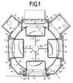
- the device has a vacuum chamber 7 which with several, evenly distributed on their outer wall arranged, window-shaped openings 24 to 27, each opening 24 to 27 a treatment station 8,9,10 or in / out station 20 is assigned, each from a box-shaped, to the respective opening 24 to 27 open, shell-shaped housing, its peripheral edge with the wall 16, 16 ', ... the vacuum chamber 7 is firmly connected.
- the vacuum chamber 7 encloses an inner cylinder 14, which is provided with openings 11, 12, 13, 21, the one with the aforementioned openings in the vacuum chamber 7 correspond and also in the bowl-shaped substrate chambers 3 to 6 used that are together with the treatment stations 8,9,10 or the in / out station 20 in the position of the inner cylinder shown in the drawing 14 containers closed on all sides form.
- the vacuum chamber wall is made of outer wall parts 16, 16 ', ... formed, each firmly with the wall parts of the treatment stations 8,9,10 or the in / out 20 are and so together with the chamber wall parts and the inner cylinder 14 outer chambers 15, 15 ', ... form. Two of these outer chambers 15, 15 ', ...
- the outer wall parts 16 ', 16' 'of these two outer chambers 15 ', 15' 'with sources 22 and 23, respectively are about the gases or monomers via recesses 18, 18 'can be admitted into the outer chambers 15' or 15 '' are, so that for example in the treatment station 8 a smoldering process and in the station 10 a coating process can be carried out can.
- the housing of the treatment station 9 are housed two sputtering cathodes 28,29, whereby the required power supply 30 on the outer wall the treatment station 9 is attached.
- the cover 33 the bottom part of the bowl-shaped housing forms, in the dash-dotted line Movable position. All chambers, namely the treatment stations 8,9,10, the lock chamber 20, the substrate chambers 3 to 6, the outer chambers 15, 15 ', .. and the inner cylinder 14 are from a common bottom plate 34 and one not cover plate shown covered so that a particularly simple structure of the device results.
- the inner cylinder 14 is over arms 35, 35 ', ... rotatably connected to the motor 34, so that from the inner cylinder 14 and the Substrate chambers 3 to 6 existing structures within the actual, from the bottom, the top plate and the outer wall parts 16, 16 ', ... Vacuum chamber can rotate.
Landscapes
- Chemical & Material Sciences (AREA)
- Chemical Kinetics & Catalysis (AREA)
- Engineering & Computer Science (AREA)
- Materials Engineering (AREA)
- Mechanical Engineering (AREA)
- Metallurgy (AREA)
- Organic Chemistry (AREA)
- Physical Vapour Deposition (AREA)
Abstract
Description
- Fig. 1
- den Schnitt quer durch die Anlage,
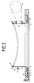
- Fig. 2
- den rahmenförmigen Teil der Schleusenstationen der Anlage nach Fig. 1, jedoch in vergrößerten Maßstab und im Schnitt,
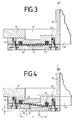
- Fig. 3
- die Dichtelemente der Schleusenstation in der Schließstellung nach Fig. 2 in vergrößertem Maßstab und
- Fig. 4
- die Dichtelemente nach Fig. 3, jedoch in der Offen-Stellung.
- 2,2'
- Substrat
- 3
- Substratkammer
- 4
- Substratkammer
- 5
- Substratkammer
- 6
- Substratkammer
- 7
- Vakuumkammer
- 8
- Behandlungsstation
- 9
- Behandlungsstation
- 10
- Behandlungsstation
- 11
- Öffnung
- 12
- Öffnung
- 13
- Öffnung
- 14
- zylindrische Wand, Innenzylinder
- 15,15',...
- Außenkammer
- 16,16',...
- Außenwand, Vakuumkammerwand
- 17,17',...
- Bohrung
- 18,18'
- Ausnehmung
- 19
- Saugstutzen
- 20
- Ein-/Ausschleusstation, Schleusenstation
- 21
- Öffnung
- 22
- Gas-Quelle
- 23
- Monomer-Quelle
- 24
- Öffnung
- 25
- Öffnung
- 26
- Öffnung
- 27
- Öffnung
- 28
- Sputterkathode
- 29
- Sputterkathode
- 30
- Stromversorgung
- 31
- Außenwand
- 32
- Bohrung
- 33
- Deckel, Schleusenklappe
- 34
- Motor
- 35,35',...
- Arm
- 36,36',...
- Seitenwand
- 37,37',...
- Nockenwelle
- 38,38',...
- Kulisse
- 39
- Dichtung
- 40,40',...
- Fußteil
- 41
- Flachdichtung
- 42
- Rahmen, Klemmrahmen
- 43
- Hilfsrahmen
- 44,44',...
- Klemmleiste
- 45
- Dichtring
- 46
- Dichtring
Claims (4)
- Vakuumbehandlungsanlage zum Aufbringen dünner Schichten auf Substrate (2,2',...), beispielsweise auf Scheinwerferreflektoren, mit mehreren, von einer ortsfesten Vakuumkammerwand (16,16',...) gehaltenen Behandlungs-(8,9,10) und/oder Ein-/Ausschleusstationen (20) und einem von der Vakuumkammerwand umschlossenen, drehbar gelagerten, die Substratkammern (3 bis 6) tragenden Gestell oder Innenzylinder (14), wobei in der Vakuumkammerwand (16,16',...) Öffnungen (24 bis 27) vorgesehen sind, mit denen die Substratkammern (3 bis 6) in Deckung bringbar sind und durch die die Behandlungsmittel auf die Substrate (2,2',...) einwirken können und/oder ein- und ausschleusbar sind, wobei eine der Substratkammern, zumindest aber die Ein-/Ausschleuskammer (20) einen Deckel oder eine Schleusenklappe (33) aufweist, die den direkten Zugang zur jeweils korrespondierenden Substratkammer gestattet, und wobei die Kammer (20) in Richtung auf den Innenzylinder (14) zu verschiebbar (A,B) und gegen die Außenwand des Zylinders (14) oder die rahmenförmige Stirnfläche der Substratkammer (3) preßbar ist und die dem Deckel (33) zugewandten Fußteile (40,40',...) der Wandteile (36,36',...) der Kammer (20) druckfest mit der radial inneren Partie einer rahmenförmigen Flachdichtung (41) aus einem flexiblen Werkstoff verbunden sind, wobei die Flachdichtung (41) ihrerseits mit ihrer radial äußeren Partie druckfest mit dem Randbereich der Öffnung (24) in der Vakuumkammerwand (16,16''') verbunden ist.
- Vakuumbehandlungsanlage nach Anspruch 1, dadurch gekennzeichnet, daß die rahmenförmige Flachdichtung (41) einerseits mit ihrer radial äußeren Randpartie zwischen dem Fußteil der Seitenwand (36,36',...) und einer Klemmleiste (44,44',...) und andererseits mit ihrer radial inneren Partie zwischen der Vakuumkammerwand (16,16',...) oder einem Hilfsrahmen (43) und einem Klemmrahmen (42) oder Klemmstücken eingespannt ist, wobei der Abstand (x) der einander parallelen Einspannstellen voneinander etwa dem zwölffachen des maximalen Verschiebewegs (y) der Seitenwand (36,36',...) gegenüber der Vakuumkammerwand (16,16''') beträgt.
- Vakuumbehandlungsanlage nach den Ansprüchen 1 und 2, dadurch gekennzeichnet , daß die rahmenförmige Flachdichtung (41) vakuumkammerseitig jeweils an Dichtwülsten oder Dichtringen (45 bzw. 46) anliegt, die ihrerseits in Nuten gehalten sind, die in das Fußteil (40) und den Hilfsrahmen (43) oder die Vakuumkammerwand (16,16''') eingeschnitten sind.
- Vakuumbehandlungsanlage nach den Ansprüchen 1 und 2, dadurch gekennzeichnet , daß die der Flachdichtung (41) zugekehrten Flächen des Fußteils (40) und des Hilfsrahmens (43) oder der Vakuumkammerwand (16,16''') so bemessen und ausgeformt sind, daß sie zusammen eine zusammenhängende Stütz- oder Anlagefläche für die Flachdichtung (41) bilden.
Applications Claiming Priority (2)
| Application Number | Priority Date | Filing Date | Title |
|---|---|---|---|
| DE19626861A DE19626861B4 (de) | 1996-07-04 | 1996-07-04 | Vakuumbehandlungsanlage zum Aufbringen dünner Schichten auf Substrate, beispielsweise auf Scheinwerferreflektoren |
| DE19626861 | 1996-07-04 |
Publications (2)
| Publication Number | Publication Date |
|---|---|
| EP0816529A1 true EP0816529A1 (de) | 1998-01-07 |
| EP0816529B1 EP0816529B1 (de) | 2001-06-13 |
Family
ID=7798850
Family Applications (1)
| Application Number | Title | Priority Date | Filing Date |
|---|---|---|---|
| EP97104908A Expired - Lifetime EP0816529B1 (de) | 1996-07-04 | 1997-03-22 | Vakuumbehandelungsanlage zum Aufbringen von Schichten auf Substrate |
Country Status (6)
| Country | Link |
|---|---|
| US (1) | US5849087A (de) |
| EP (1) | EP0816529B1 (de) |
| JP (1) | JP4119499B2 (de) |
| KR (1) | KR100260605B1 (de) |
| DE (2) | DE19626861B4 (de) |
| ES (1) | ES2159065T3 (de) |
Cited By (2)
| Publication number | Priority date | Publication date | Assignee | Title |
|---|---|---|---|---|
| EP0857518A1 (de) * | 1997-02-10 | 1998-08-12 | Leybold Systems GmbH | Verfahren und Vorrichtung zur Schutzbeschichtung von Verspiegelungsschichten |
| EP0943699A1 (de) * | 1998-02-19 | 1999-09-22 | Leybold Systems GmbH | Schleuseneinrichtung zum Ein- und/oder Ausbringen von Substraten in und/oder aus einer Behandlungskammer |
Families Citing this family (15)
| Publication number | Priority date | Publication date | Assignee | Title |
|---|---|---|---|---|
| WO1998028460A1 (de) * | 1996-12-23 | 1998-07-02 | Balzers Aktiengesellschaft | Vakuumbehandlungsanlage |
| DE19807031A1 (de) * | 1998-02-19 | 1999-08-26 | Leybold Systems Gmbh | Schleuseneinrichtung zum Ein- und/oder Ausbringen von Substraten in und/oder aus einer Behandlungskammer |
| DE19819726A1 (de) * | 1998-05-02 | 1999-11-04 | Leybold Systems Gmbh | Vakuumbehandlungsanlage zum Aufbringen dünner, harter Schichten |
| US6264804B1 (en) | 2000-04-12 | 2001-07-24 | Ske Technology Corp. | System and method for handling and masking a substrate in a sputter deposition system |
| US6355723B1 (en) | 2000-06-22 | 2002-03-12 | General Electric Co. | Dark colored thermoplastic compositions, articles molded therefrom, and article preparation methods |
| US20030185973A1 (en) * | 2002-03-30 | 2003-10-02 | Crawley Richard L. | Water vapor plasma method of increasing the surface energy of a surface |
| US7329462B2 (en) * | 2002-08-23 | 2008-02-12 | General Electric Company | Reflective article and method for the preparation thereof |
| US7300742B2 (en) * | 2002-08-23 | 2007-11-27 | General Electric Company | Data storage medium and method for the preparation thereof |
| US7132149B2 (en) | 2002-08-23 | 2006-11-07 | General Electric Company | Data storage medium and method for the preparation thereof |
| US7128959B2 (en) * | 2002-08-23 | 2006-10-31 | General Electric Company | Reflective article and method for the preparation thereof |
| DE102004055388A1 (de) * | 2004-11-17 | 2006-05-18 | Jrw Technology + Engineering Gmbh | Vorrichtung zur Bearbeitung von Werkstücken im Vakuum |
| DE102005056323A1 (de) * | 2005-11-25 | 2007-05-31 | Aixtron Ag | Prozesskammermodul zum gleichzeitigen Abscheiden von Schichten auf mehreren Substraten |
| DE102006024638A1 (de) * | 2006-05-19 | 2007-11-22 | Ptm Packaging Tools Machinery Pte.Ltd. | Verfahren und Vorrichtung zur Behandlung von Objekten |
| DE102008011774B4 (de) * | 2008-02-28 | 2021-12-09 | Krones Aktiengesellschaft | Schleusenvorrichtung zum Ein- und Ausbringen von Behältern in und aus einer Vakuumbehandlungskammer |
| CN103943533B (zh) * | 2013-01-23 | 2017-12-29 | 上海微电子装备(集团)股份有限公司 | 密封对接装置 |
Citations (2)
| Publication number | Priority date | Publication date | Assignee | Title |
|---|---|---|---|---|
| DE2454544A1 (de) * | 1973-11-22 | 1975-07-31 | Balzers Hochvakuum | Vakuumbeschichtungsanlage |
| EP0555764A1 (de) * | 1992-02-12 | 1993-08-18 | Balzers Aktiengesellschaft | Vakuumbearbeitungsanlage |
Family Cites Families (2)
| Publication number | Priority date | Publication date | Assignee | Title |
|---|---|---|---|---|
| US3856654A (en) * | 1971-08-26 | 1974-12-24 | Western Electric Co | Apparatus for feeding and coating masses of workpieces in a controlled atmosphere |
| DE2848480C2 (de) * | 1978-11-08 | 1984-11-08 | Siemens AG, 1000 Berlin und 8000 München | Vorrichtung zum Aufbringen von Schichten auf Träger unter Vakuum |
-
1996
- 1996-07-04 DE DE19626861A patent/DE19626861B4/de not_active Expired - Fee Related
-
1997
- 1997-03-22 EP EP97104908A patent/EP0816529B1/de not_active Expired - Lifetime
- 1997-03-22 DE DE59703760T patent/DE59703760D1/de not_active Expired - Lifetime
- 1997-03-22 ES ES97104908T patent/ES2159065T3/es not_active Expired - Lifetime
- 1997-06-16 KR KR1019970024811A patent/KR100260605B1/ko not_active Expired - Fee Related
- 1997-07-01 US US08/886,675 patent/US5849087A/en not_active Expired - Lifetime
- 1997-07-04 JP JP17965297A patent/JP4119499B2/ja not_active Expired - Fee Related
Patent Citations (2)
| Publication number | Priority date | Publication date | Assignee | Title |
|---|---|---|---|---|
| DE2454544A1 (de) * | 1973-11-22 | 1975-07-31 | Balzers Hochvakuum | Vakuumbeschichtungsanlage |
| EP0555764A1 (de) * | 1992-02-12 | 1993-08-18 | Balzers Aktiengesellschaft | Vakuumbearbeitungsanlage |
Cited By (2)
| Publication number | Priority date | Publication date | Assignee | Title |
|---|---|---|---|---|
| EP0857518A1 (de) * | 1997-02-10 | 1998-08-12 | Leybold Systems GmbH | Verfahren und Vorrichtung zur Schutzbeschichtung von Verspiegelungsschichten |
| EP0943699A1 (de) * | 1998-02-19 | 1999-09-22 | Leybold Systems GmbH | Schleuseneinrichtung zum Ein- und/oder Ausbringen von Substraten in und/oder aus einer Behandlungskammer |
Also Published As
| Publication number | Publication date |
|---|---|
| DE59703760D1 (de) | 2001-07-19 |
| JPH1060644A (ja) | 1998-03-03 |
| US5849087A (en) | 1998-12-15 |
| EP0816529B1 (de) | 2001-06-13 |
| KR980009506A (ko) | 1998-04-30 |
| DE19626861B4 (de) | 2009-04-16 |
| ES2159065T3 (es) | 2001-09-16 |
| JP4119499B2 (ja) | 2008-07-16 |
| DE19626861A1 (de) | 1998-01-08 |
| KR100260605B1 (ko) | 2000-07-01 |
Similar Documents
| Publication | Publication Date | Title |
|---|---|---|
| EP0816529B1 (de) | Vakuumbehandelungsanlage zum Aufbringen von Schichten auf Substrate | |
| DE2454544C3 (de) | Vakuumbeschichtungsanlage | |
| EP0837154B1 (de) | Vakuumbeschichtungsanlage | |
| EP0312694B1 (de) | Vorrichtung nach dem Karussell-Prinzip zum Beschichten von Substraten | |
| DE3788973T2 (de) | Verfahren und Vorrichtung zur Handhabung und Behandlung von scheibenartigen Materialien. | |
| EP0555764B1 (de) | Vakuumbearbeitungsanlage | |
| DE69531365T2 (de) | Unterteilte Substrat Behandlungskammer | |
| DE2609115C2 (de) | Vakuum-Zerstäubungsvorrichtung | |
| EP1507894B1 (de) | Beschichtungsvorrichtung mit transporteinrichtung | |
| DE4009603A1 (de) | Vorrichtung zum ein- und ausschleusen eines werkstuecks in eine vakuumkammer | |
| DE2047749A1 (de) | Zirkuläres System zur kontinuierlichen Verrichtung verschiedener im Vakuum durch zuführender Prozesse | |
| DE3047441A1 (de) | Vorrichtung zum beschichten von mikroplaettchen | |
| DE3507337A1 (de) | Vorrichtung zur durchfuehrung von prozessen im vakuum | |
| DE29520391U1 (de) | Vakuumanlage zur Oberflächenbearbeitung von Werkstücken | |
| EP1571234B1 (de) | Verfahren für den Betrieb einer Inline-Beschichtungsanlage | |
| DE69504716T2 (de) | System zum Behandeln und zum Handhaben von Substraten für Flachdisplays | |
| CA2234351C (en) | Vacuum treatment system for depositing thin coatings | |
| DE19606463C2 (de) | Mehrkammer-Kathodenzerstäubungsvorrichtung | |
| DE69102536T2 (de) | Verfahren und vorrichtung zum verringern der wafer-verunreinigung. | |
| EP0389820B1 (de) | Vorrichtung zum Ein- und Ausschleusen eines Werkstücks in eine Vakuumkammer | |
| CH688043A5 (de) | Vakuumbehandlungsanlage und Ventilanordnung. | |
| EP1617456B1 (de) | Antriebsmechanismus für eine Vakuum-Behandlungsanlage | |
| DE19624609B4 (de) | Vakuumbehandlungsanlage zum Aufbringen dünner Schichten auf Substrate, beispielsweise auf Scheinwerferreflektoren | |
| EP0856594B1 (de) | Vorrichtung zur Plasma-Oberflächenbehandlung von Werkstücken | |
| DE10348281B4 (de) | Vakuum-Behandlungsanlage für ebene rechteckige oder quadratische Substrate |
Legal Events
| Date | Code | Title | Description |
|---|---|---|---|
| PUAI | Public reference made under article 153(3) epc to a published international application that has entered the european phase |
Free format text: ORIGINAL CODE: 0009012 |
|
| AK | Designated contracting states |
Kind code of ref document: A1 Designated state(s): DE ES FR GB IT SE |
|
| 17P | Request for examination filed |
Effective date: 19980121 |
|
| AKX | Designation fees paid |
Free format text: DE ES FR GB IT SE |
|
| RBV | Designated contracting states (corrected) |
Designated state(s): DE ES FR GB IT SE |
|
| GRAG | Despatch of communication of intention to grant |
Free format text: ORIGINAL CODE: EPIDOS AGRA |
|
| GRAG | Despatch of communication of intention to grant |
Free format text: ORIGINAL CODE: EPIDOS AGRA |
|
| GRAH | Despatch of communication of intention to grant a patent |
Free format text: ORIGINAL CODE: EPIDOS IGRA |
|
| 17Q | First examination report despatched |
Effective date: 20001127 |
|
| GRAH | Despatch of communication of intention to grant a patent |
Free format text: ORIGINAL CODE: EPIDOS IGRA |
|
| RAP1 | Party data changed (applicant data changed or rights of an application transferred) |
Owner name: UNAXIS DEUTSCHLAND HOLDING GMBH |
|
| GRAA | (expected) grant |
Free format text: ORIGINAL CODE: 0009210 |
|
| AK | Designated contracting states |
Kind code of ref document: B1 Designated state(s): DE ES FR GB IT SE |
|
| REF | Corresponds to: |
Ref document number: 59703760 Country of ref document: DE Date of ref document: 20010719 |
|
| ITF | It: translation for a ep patent filed | ||
| GBT | Gb: translation of ep patent filed (gb section 77(6)(a)/1977) |
Effective date: 20010820 |
|
| REG | Reference to a national code |
Ref country code: ES Ref legal event code: FG2A Ref document number: 2159065 Country of ref document: ES Kind code of ref document: T3 |
|
| ET | Fr: translation filed | ||
| REG | Reference to a national code |
Ref country code: GB Ref legal event code: IF02 |
|
| PLBE | No opposition filed within time limit |
Free format text: ORIGINAL CODE: 0009261 |
|
| STAA | Information on the status of an ep patent application or granted ep patent |
Free format text: STATUS: NO OPPOSITION FILED WITHIN TIME LIMIT |
|
| 26N | No opposition filed | ||
| PGFP | Annual fee paid to national office [announced via postgrant information from national office to epo] |
Ref country code: FR Payment date: 20050211 Year of fee payment: 9 |
|
| PGFP | Annual fee paid to national office [announced via postgrant information from national office to epo] |
Ref country code: GB Payment date: 20050214 Year of fee payment: 9 |
|
| PGFP | Annual fee paid to national office [announced via postgrant information from national office to epo] |
Ref country code: SE Payment date: 20050224 Year of fee payment: 9 |
|
| PGFP | Annual fee paid to national office [announced via postgrant information from national office to epo] |
Ref country code: ES Payment date: 20050304 Year of fee payment: 9 |
|
| PG25 | Lapsed in a contracting state [announced via postgrant information from national office to epo] |
Ref country code: GB Free format text: LAPSE BECAUSE OF NON-PAYMENT OF DUE FEES Effective date: 20060322 |
|
| PG25 | Lapsed in a contracting state [announced via postgrant information from national office to epo] |
Ref country code: SE Free format text: LAPSE BECAUSE OF NON-PAYMENT OF DUE FEES Effective date: 20060323 Ref country code: ES Free format text: LAPSE BECAUSE OF NON-PAYMENT OF DUE FEES Effective date: 20060323 |
|
| EUG | Se: european patent has lapsed | ||
| GBPC | Gb: european patent ceased through non-payment of renewal fee |
Effective date: 20060322 |
|
| REG | Reference to a national code |
Ref country code: FR Ref legal event code: ST Effective date: 20061130 |
|
| REG | Reference to a national code |
Ref country code: ES Ref legal event code: FD2A Effective date: 20060323 |
|
| PG25 | Lapsed in a contracting state [announced via postgrant information from national office to epo] |
Ref country code: FR Free format text: LAPSE BECAUSE OF NON-PAYMENT OF DUE FEES Effective date: 20060331 |
|
| PGFP | Annual fee paid to national office [announced via postgrant information from national office to epo] |
Ref country code: DE Payment date: 20150320 Year of fee payment: 19 |
|
| PGFP | Annual fee paid to national office [announced via postgrant information from national office to epo] |
Ref country code: IT Payment date: 20150326 Year of fee payment: 19 |
|
| REG | Reference to a national code |
Ref country code: DE Ref legal event code: R119 Ref document number: 59703760 Country of ref document: DE |
|
| PG25 | Lapsed in a contracting state [announced via postgrant information from national office to epo] |
Ref country code: DE Free format text: LAPSE BECAUSE OF NON-PAYMENT OF DUE FEES Effective date: 20161001 |
|
| PG25 | Lapsed in a contracting state [announced via postgrant information from national office to epo] |
Ref country code: IT Free format text: LAPSE BECAUSE OF NON-PAYMENT OF DUE FEES Effective date: 20160322 |