EP0816778A2 - Soupape de service dans un conduit d'aspiration - Google Patents
Soupape de service dans un conduit d'aspiration Download PDFInfo
- Publication number
- EP0816778A2 EP0816778A2 EP97630037A EP97630037A EP0816778A2 EP 0816778 A2 EP0816778 A2 EP 0816778A2 EP 97630037 A EP97630037 A EP 97630037A EP 97630037 A EP97630037 A EP 97630037A EP 0816778 A2 EP0816778 A2 EP 0816778A2
- Authority
- EP
- European Patent Office
- Prior art keywords
- shaft
- valve
- evaporator
- suction pipe
- shell
- Prior art date
- Legal status (The legal status is an assumption and is not a legal conclusion. Google has not performed a legal analysis and makes no representation as to the accuracy of the status listed.)
- Granted
Links
Images

Classifications
-
- F—MECHANICAL ENGINEERING; LIGHTING; HEATING; WEAPONS; BLASTING
- F25—REFRIGERATION OR COOLING; COMBINED HEATING AND REFRIGERATION SYSTEMS; HEAT PUMP SYSTEMS; MANUFACTURE OR STORAGE OF ICE; LIQUEFACTION SOLIDIFICATION OF GASES
- F25B—REFRIGERATION MACHINES, PLANTS OR SYSTEMS; COMBINED HEATING AND REFRIGERATION SYSTEMS; HEAT PUMP SYSTEMS
- F25B41/00—Fluid-circulation arrangements
- F25B41/20—Disposition of valves, e.g. of on-off valves or flow control valves
- F25B41/22—Disposition of valves, e.g. of on-off valves or flow control valves between evaporator and compressor
-
- F—MECHANICAL ENGINEERING; LIGHTING; HEATING; WEAPONS; BLASTING
- F25—REFRIGERATION OR COOLING; COMBINED HEATING AND REFRIGERATION SYSTEMS; HEAT PUMP SYSTEMS; MANUFACTURE OR STORAGE OF ICE; LIQUEFACTION SOLIDIFICATION OF GASES
- F25B—REFRIGERATION MACHINES, PLANTS OR SYSTEMS; COMBINED HEATING AND REFRIGERATION SYSTEMS; HEAT PUMP SYSTEMS
- F25B2339/00—Details of evaporators; Details of condensers
- F25B2339/02—Details of evaporators
- F25B2339/024—Evaporators with refrigerant in a vessel in which is situated a heat exchanger
- F25B2339/0242—Evaporators with refrigerant in a vessel in which is situated a heat exchanger having tubular elements
-
- F—MECHANICAL ENGINEERING; LIGHTING; HEATING; WEAPONS; BLASTING
- F25—REFRIGERATION OR COOLING; COMBINED HEATING AND REFRIGERATION SYSTEMS; HEAT PUMP SYSTEMS; MANUFACTURE OR STORAGE OF ICE; LIQUEFACTION SOLIDIFICATION OF GASES
- F25B—REFRIGERATION MACHINES, PLANTS OR SYSTEMS; COMBINED HEATING AND REFRIGERATION SYSTEMS; HEAT PUMP SYSTEMS
- F25B2400/00—Component parts or details not otherwise provided for in this subclass
- F25B2400/13—Economisers
-
- F—MECHANICAL ENGINEERING; LIGHTING; HEATING; WEAPONS; BLASTING
- F25—REFRIGERATION OR COOLING; COMBINED HEATING AND REFRIGERATION SYSTEMS; HEAT PUMP SYSTEMS; MANUFACTURE OR STORAGE OF ICE; LIQUEFACTION SOLIDIFICATION OF GASES
- F25B—REFRIGERATION MACHINES, PLANTS OR SYSTEMS; COMBINED HEATING AND REFRIGERATION SYSTEMS; HEAT PUMP SYSTEMS
- F25B2400/00—Component parts or details not otherwise provided for in this subclass
- F25B2400/23—Separators
-
- Y—GENERAL TAGGING OF NEW TECHNOLOGICAL DEVELOPMENTS; GENERAL TAGGING OF CROSS-SECTIONAL TECHNOLOGIES SPANNING OVER SEVERAL SECTIONS OF THE IPC; TECHNICAL SUBJECTS COVERED BY FORMER USPC CROSS-REFERENCE ART COLLECTIONS [XRACs] AND DIGESTS
- Y10—TECHNICAL SUBJECTS COVERED BY FORMER USPC
- Y10T—TECHNICAL SUBJECTS COVERED BY FORMER US CLASSIFICATION
- Y10T137/00—Fluid handling
- Y10T137/5762—With leakage or drip collecting
-
- Y—GENERAL TAGGING OF NEW TECHNOLOGICAL DEVELOPMENTS; GENERAL TAGGING OF CROSS-SECTIONAL TECHNOLOGIES SPANNING OVER SEVERAL SECTIONS OF THE IPC; TECHNICAL SUBJECTS COVERED BY FORMER USPC CROSS-REFERENCE ART COLLECTIONS [XRACs] AND DIGESTS
- Y10—TECHNICAL SUBJECTS COVERED BY FORMER USPC
- Y10T—TECHNICAL SUBJECTS COVERED BY FORMER US CLASSIFICATION
- Y10T137/00—Fluid handling
- Y10T137/598—With repair, tapping, assembly, or disassembly means
- Y10T137/6065—Assembling or disassembling reciprocating valve
-
- Y—GENERAL TAGGING OF NEW TECHNOLOGICAL DEVELOPMENTS; GENERAL TAGGING OF CROSS-SECTIONAL TECHNOLOGIES SPANNING OVER SEVERAL SECTIONS OF THE IPC; TECHNICAL SUBJECTS COVERED BY FORMER USPC CROSS-REFERENCE ART COLLECTIONS [XRACs] AND DIGESTS
- Y10—TECHNICAL SUBJECTS COVERED BY FORMER USPC
- Y10T—TECHNICAL SUBJECTS COVERED BY FORMER US CLASSIFICATION
- Y10T137/00—Fluid handling
- Y10T137/8593—Systems
- Y10T137/86187—Plural tanks or compartments connected for serial flow
- Y10T137/86196—Separable with valved-connecting passage
Definitions
- This invention relates to a refrigeration system and, in particular, to apparatus for improving and compacting a refrigeration system.
- a suction service valve is mounted in the refrigerant line connecting the outlet of the evaporator cooler with the suction inlet of the compressor.
- the suction service valve can be closed during maintenance periods to isolate the cooler from the compressor to better facilitate servicing of the various system components.
- the valve may not, under certain conditions, be provided as part of the overall system. Attempts to retrofit these systems with a suction service valve at some later point after the units have been placed in the field have generally proven to be less than satisfactory.
- the present invention is attained by means of a suction service valve for connecting the evaporator of a refrigeration system with the system compressor.
- the valve can be cycled to isolate the evaporator cooler of a refrigeration system from the system compressor and includes a suction pipe that is at least partially contained inside the shell of the evaporator cooler.
- a shaft is rotatably mounted within the suction pipe and is connected to a valve located inside the evaporator shell by means of a linkage mechanism that is passed downwardly through the suction pipe. By rotating the shaft, the valve can be moved from an opened position beneath the bottom opening of the pipe to a closed position in sealing contact against the bottom of the pipe to prevent refrigerant from moving between the evaporator and the compressor.
- a cylindrical sleeve is mounted inside a flange connection of an evaporator which is typically used to couple the evaporator to the suction side of a compressor.
- a shaft is rotatably mounted in the sleeve and is connected to a valve that hangs down below the sleeve.
- the valve is configured so that it can be inserted along with the sleeve into an existing connection without having to remove the connection from the evaporator shell.
- the valve is joined to the shaft by a linkage so that rotation of the shaft will draw the valve upwardly from an opened position into a closed position against the bottom opening of the sleeve.
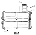
- a front elevation of a compact chiller unit generally referenced 10, wherein the cooler shell 12 is mounted over the condenser shell 24.
- a screw compressor 17 is mounted on top of the cooler shell in close proximity therewith.
- a low profile flange connection containing a suction service valve is used to place the evaporator in fluid flow communication with the inlet to the compressor.
- the connection occupies little space and thus permits the compressor to be mounted as close as possible to the evaporator shell.
- the valve is assembled upon a sleeve and the assembly is passed into an existing flange coupling thus permitting the valve to be easily retrofitted to existing systems in the field.
- the present chiller system 10 employs an evaporator 12 to chill water.
- the water enters the evaporator shell through an inlet port 13 and is circulated through a series of tubes 15 before being discharged through an exit port 16.
- the cooler is flooded with liquid refrigerant at a suitably low temperature so that it absorbs heat from the water being circulated through the heat exchanger tubes. Accordingly, some of the refrigerant is evaporated to a vapor which is collected in the top section of the evaporator shell and then passed on to the system compressor 17.
- the compressor employed in the system is a screw compressor although the practice of the present invention is not limited to use in conjunction with this particular type of compressor and has wider application in various refrigeration systems using other types of compressors.
- the suction side of the compressor is connected directly to a flanged connector 19 mounted in the top of the evaporator shell so that vapor collected in the shell will pass directly into the suction inlet of the compressor when the system is being serviced.
- a suction service valve is contained within the flanged connector which can be manually cycled to shut off the flow of refrigerant from the evaporator to the compressor.
- the rotors of the compressor are coupled to a compressor motor 20 by means of a gear train 21. As is typical in most screw compressors, lubricating oil is distributed to the rotors and the bearings of the machine and, as a result, oil is compressed along with the refrigerant within the compression chamber.
- the compressed gas that is discharged from the compressor is delivered to an oil separator 33 by means of a gas line 32.
- the compressed gas entering the separator is initially directed against one side wall 35 of the separator shell through a discharge nozzle. Upon impact, a portion of the oil is reduced to a liquid that drops to the bottom of the tank.
- the remaining gas mixture is then passed through a wire mesh screen 37 where the remaining oil is separated from the refrigerant vapor and is collected with the previously separated oil in the bottom of the shell.
- An oil retum line 36 is connected into the bottom of the separator shell through which the separated oil is retumed to the compressor pump for recirculation.
- a small prelube pump 30 is connected into the oil return line which is actuated for a short period of time at start up to pre-lubricate the rotors and bearings of the machine.
- the prelube pump is shut down and the oil is rerouted about the pump by means of the check valve network 39.
- Refrigerant vapor is drawn out of the separator through a vapor line 45 and delivered into the shell of condenser 24.
- the present system utilizes a water cooled condenser although any type of condenser that is known and used in the art may be similarly employed. Cooling water is delivered into the shell via inlet 46 and is passed through a series of heat exchanger tubes (not shown) prior to leaving the condenser through outlet 47. Heat from the refrigerant is rejected into the cooling water thus reducing the refrigerant to a liquid is collected in the bottom of the condenser shell.
- the liquid refrigerant collected in the condenser passes through a liquid line 48 into a flash tank economizer 23.
- the economizer is housed within a vertically disposed tank 50 that is attached to a base 54 which containing a refrigerant inlet 49.
- a stand pipe 55 is mounted on the base which surrounds a smaller diameter refrigerant tube to create an expansion chamber therebetween.
- the tube delivers the incoming liquid refrigerant to an electronically controlled expansion valve (EXV) 56, the function of which is described in greater detail in U.S. Patent 4,523,435 and is incorporated by reference.
- the operation of the EXV is regulated by a controller unit 60 in response to one or more sensed conditions within the system.
- the EXV serves to rapidly expand or flash the incoming liquid refrigerant to a lower temperature and pressure wherein some of the liquid is vaporized.
- the flash gas is collected in the top section of the tank and the liquid is collected in the bottom of the tank.
- the collected flash gas is fed back to the compressor through the compressor motor section and thus provides for additional motor cooling.
- the flash gas is introduced into the compression chamber of the compressor downstream from the inlet within a region where the chamber pressure is about equal to or slightly less than the economizer pressure maintained in the economizer.
- the liquid that is collected in the bottom of the economizer tank is expanded or throttled a second time to a lower temperature and pressure.
- the second expansion is accomplished by a float type flow metering device.
- This flow metering device is disclosed in U.S. patent 5,285,653 and the disclosure in this patent is herein incorporated by reference.
- An annular float surrounds the standpipe 55 and is adapted to float upon the liquid refrigerant contained in the sump of the economizer tank.
- a series of vertically disposed metering slots are circumferentially spaced about the wetted lower section of the stand pipe and a metering sleeve is slidably mounted within the standpipe behind the slots.
- the sleeve is connected to the float and is thus positioned vertically as the float moves up or down in the liquid refrigerant to vary the size of the slotted openings in response to the level of refrigerant in the sump.
- a vapor injection duct 52 supplies refrigerant vapor from the oil separator at a high pressure beneath the float to maintain a positive buoyancy therein relative to the refrigerant liquid in the economizer tank.
- the twice expanded throttled refrigerant two phase fluid in the expansion chamber is delivered into the evaporator via liquid line 22 where it absorbs heat from the water being chilled and is thus reduced once again to a vapor.
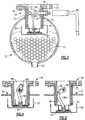
- Fig. 3 is a cross sectional view of the evaporator cooler shell showing the water tubes 15 mounted in the bottom of the shell. Liquid refrigerant in the shell is maintained at a level so that the water tubes are completely covered with the liquid phase refrigerant. The vapor phase is generated in the shell collected in the top of the shell.
- a typical flanged connector 70 is mounted in the top of the evaporator shell with the cylindrical body of the connector extending downward some distance into the shell.
- a flanged sleeve 72 is inserted downwardly into the connector so that the flange 73 of the sleeve rests upon the flange 74 of the connector.
- the flanges are secured together in face-to-face contact by suitable means of threaded fasteners 75.
- Aligned bolting holes 76 are also spaced about the flanges that permits the connector 71 (Fig. 2) to be bolted to a mating connector in the suction line of the compressor.
- a vertically disposed shaft 77 is mounted for rotation in bearing surface 78-78 provided in the sleeve 72.
- One end of the shaft extends horizontally through both the sleeve body and the connector body and contains square head 79 at its extended end that is engageable by a suitable tool 80 for manually rotating the shaft in the bearing surfaces.
- Seals such as O-ring seals 82-82 are mounted between the sleeve 72 and the connector 19, as well as between the shaft and the sleeve to prevent refrigerant from escaping from the system.
- the body section of the sleeve extends downwardly to a slightly lower elevation than the body section of the connector.
- the central portion of the shaft 77 contains a square section 83.
- a crank arm 85 is affixed to the square section of the arm so that it will rotate with the shaft.
- the length of the crank arm is slightly less than the radius of the sleeve opening 86 so that the arm can swing freely within the opening.
- a valve 87 is connected to the crank arm by a link 88 which is pinned for rotation at one end in the crank arm and at the other end in an ear 89 that is affixed to the top of the valve.
- a plurality of vertically disposed guide pins are mounted iii the top of the valve that extend upwardly into the sleeve opening to guide the valve as it is moved between the opened position shown in Fig. 4 and the closed position shown in Fig. 5.
- An oil trap 93 is mounted inside the evaporator shell immediately beneath the opening in the connector to capture any oil that might pass downward from the compressor into the evaporator.
- the trap also serves to collect oil that is carried over from the evaporation process.
- the valve When the valve is in the opened position as shown in Fig. 5, the valve is situated just above the floor of the trap. Revolving the shaft from the open position to the closed position as shown in Fig. 4 causes the linkage to draw the valve upwardly into sealing contact against the lower face of the sleeve thus preventing refrigerant from flow between the evaporator and the compressor. A slight amount of over rotation is provided by the linkage so that the valve locks in the closed position.
- the present suction service valve is a space saving device that can be installed as original equipment in refrigeration systems or easily retrofitted to existing systems that are in the field.
Landscapes
- Engineering & Computer Science (AREA)
- Physics & Mathematics (AREA)
- Mechanical Engineering (AREA)
- Thermal Sciences (AREA)
- General Engineering & Computer Science (AREA)
- Compressor (AREA)
- Applications Or Details Of Rotary Compressors (AREA)
- Lift Valve (AREA)
- Check Valves (AREA)
Applications Claiming Priority (2)
| Application Number | Priority Date | Filing Date | Title |
|---|---|---|---|
| US672761 | 1996-06-28 | ||
| US08/672,761 US5829265A (en) | 1996-06-28 | 1996-06-28 | Suction service valve |
Publications (3)
| Publication Number | Publication Date |
|---|---|
| EP0816778A2 true EP0816778A2 (fr) | 1998-01-07 |
| EP0816778A3 EP0816778A3 (fr) | 1999-07-21 |
| EP0816778B1 EP0816778B1 (fr) | 2004-11-24 |
Family
ID=24699907
Family Applications (1)
| Application Number | Title | Priority Date | Filing Date |
|---|---|---|---|
| EP97630037A Expired - Lifetime EP0816778B1 (fr) | 1996-06-28 | 1997-06-20 | System de refrigeration comprenant une soupape de service dans un conduit d'aspiration |
Country Status (10)
| Country | Link |
|---|---|
| US (1) | US5829265A (fr) |
| EP (1) | EP0816778B1 (fr) |
| JP (1) | JP3124950B2 (fr) |
| KR (1) | KR100235171B1 (fr) |
| CN (1) | CN1091509C (fr) |
| AU (1) | AU710090B2 (fr) |
| BR (1) | BR9703759A (fr) |
| DE (1) | DE69731689T2 (fr) |
| ES (1) | ES2233994T3 (fr) |
| MX (1) | MX9704901A (fr) |
Families Citing this family (16)
| Publication number | Priority date | Publication date | Assignee | Title |
|---|---|---|---|---|
| US6024242A (en) * | 1996-12-24 | 2000-02-15 | Eidson Steel Products, Inc. | Removably insertable internal containment reservoir |
| US6202438B1 (en) * | 1999-11-23 | 2001-03-20 | Scroll Technologies | Compressor economizer circuit with check valve |
| US7299649B2 (en) * | 2003-12-09 | 2007-11-27 | Emerson Climate Technologies, Inc. | Vapor injection system |
| US7395678B2 (en) * | 2004-04-02 | 2008-07-08 | Parker-Hannifin Corp. | Refrigerant receiving apparatus |
| US6941769B1 (en) | 2004-04-08 | 2005-09-13 | York International Corporation | Flash tank economizer refrigeration systems |
| US7997091B2 (en) * | 2004-04-22 | 2011-08-16 | Carrier Corporation | Control scheme for multiple operating parameters in economized refrigerant system |
| US8037710B2 (en) | 2005-08-22 | 2011-10-18 | Emerson Climate Technologies, Inc. | Compressor with vapor injection system |
| US7275385B2 (en) * | 2005-08-22 | 2007-10-02 | Emerson Climate Technologies, Inc. | Compressor with vapor injection system |
| DK1974171T3 (da) * | 2006-09-29 | 2014-08-18 | Carrier Corp | Kompressionssystem til kølemiddeldamp med flash tank modtager |
| US7707850B2 (en) * | 2007-06-07 | 2010-05-04 | Johnson Controls Technology Company | Drainage mechanism for a flooded evaporator |
| CN102165276B (zh) * | 2008-09-29 | 2013-03-27 | 开利公司 | 具有闪蒸罐经济器的蒸气压缩系统及其控制方法 |
| US20130255308A1 (en) * | 2012-03-29 | 2013-10-03 | Johnson Controls Technology Company | Chiller or heat pump with a falling film evaporator and horizontal oil separator |
| CN106871501A (zh) | 2015-12-10 | 2017-06-20 | 开利公司 | 一种经济器及具有其的制冷系统 |
| CN205605462U (zh) * | 2016-05-06 | 2016-09-28 | 艾拉斯科普库空气动力股份有限公司 | 离心式压缩机 |
| US11022355B2 (en) | 2017-03-24 | 2021-06-01 | Johnson Controls Technology Company | Converging suction line for compressor |
| CN109210810A (zh) | 2017-07-04 | 2019-01-15 | 开利公司 | 制冷系统及用于制冷系统的启动控制方法 |
Citations (2)
| Publication number | Priority date | Publication date | Assignee | Title |
|---|---|---|---|---|
| US4523435A (en) | 1983-12-19 | 1985-06-18 | Carrier Corporation | Method and apparatus for controlling a refrigerant expansion valve in a refrigeration system |
| US5285653A (en) | 1992-12-30 | 1994-02-15 | Carrier Corporation | Refrigerant flow control device |
Family Cites Families (15)
| Publication number | Priority date | Publication date | Assignee | Title |
|---|---|---|---|---|
| GB418003A (en) * | 1933-04-18 | 1934-10-17 | Ernest Newell & Company Ltd | Improvements in or relating to valves for controlling gas or air under pressure |
| US2049230A (en) * | 1934-08-30 | 1936-07-28 | Gen Motors Corp | Refrigerating apparatus |
| US2315031A (en) * | 1939-12-07 | 1943-03-30 | Edwin L Wiegand | Valve means |
| US2338953A (en) * | 1942-08-27 | 1944-01-11 | Gen Motors Corp | Refrigerating apparatus |
| GB667177A (en) * | 1949-01-27 | 1952-02-27 | Normalair Ltd | Improvements in or relating to flap valves |
| US2644479A (en) * | 1950-07-21 | 1953-07-07 | Globe Automatic Sprinkler Co | Dry pipe valve |
| US3473569A (en) * | 1966-03-29 | 1969-10-21 | Dover Corp | Coupler |
| US3472482A (en) * | 1966-06-10 | 1969-10-14 | Parker Hannifin Corp | Fueling nozzle |
| US3656710A (en) * | 1970-07-09 | 1972-04-18 | Golconda Corp | Bottom opening valve |
| JPS49228Y1 (fr) * | 1970-11-18 | 1974-01-07 | ||
| US3721424A (en) * | 1971-06-14 | 1973-03-20 | Union Tank Car Co | Crank operated tank bottom plug valve |
| US3765192A (en) * | 1972-08-17 | 1973-10-16 | D Root | Evaporator and/or condenser for refrigeration or heat pump systems |
| JPS61262567A (ja) * | 1985-05-17 | 1986-11-20 | 株式会社荏原製作所 | 冷凍機用蒸発器 |
| JP3360343B2 (ja) * | 1993-03-23 | 2002-12-24 | ダイキン工業株式会社 | 満液式蒸発器 |
| JP5434936B2 (ja) | 2011-02-22 | 2014-03-05 | 株式会社デンソー | 車両用操作入力装置および車両用操作入力システム |
-
1996
- 1996-06-28 US US08/672,761 patent/US5829265A/en not_active Expired - Lifetime
-
1997
- 1997-06-20 DE DE69731689T patent/DE69731689T2/de not_active Expired - Lifetime
- 1997-06-20 EP EP97630037A patent/EP0816778B1/fr not_active Expired - Lifetime
- 1997-06-20 ES ES97630037T patent/ES2233994T3/es not_active Expired - Lifetime
- 1997-06-26 AU AU27537/97A patent/AU710090B2/en not_active Ceased
- 1997-06-27 BR BR9703759A patent/BR9703759A/pt not_active IP Right Cessation
- 1997-06-27 CN CN97113992A patent/CN1091509C/zh not_active Expired - Fee Related
- 1997-06-27 KR KR1019970028107A patent/KR100235171B1/ko not_active Expired - Fee Related
- 1997-06-27 MX MX9704901A patent/MX9704901A/es not_active IP Right Cessation
- 1997-06-30 JP JP09173764A patent/JP3124950B2/ja not_active Expired - Fee Related
Patent Citations (2)
| Publication number | Priority date | Publication date | Assignee | Title |
|---|---|---|---|---|
| US4523435A (en) | 1983-12-19 | 1985-06-18 | Carrier Corporation | Method and apparatus for controlling a refrigerant expansion valve in a refrigeration system |
| US5285653A (en) | 1992-12-30 | 1994-02-15 | Carrier Corporation | Refrigerant flow control device |
Also Published As
| Publication number | Publication date |
|---|---|
| JP3124950B2 (ja) | 2001-01-15 |
| MX9704901A (es) | 1997-12-31 |
| EP0816778B1 (fr) | 2004-11-24 |
| JPH1073341A (ja) | 1998-03-17 |
| CN1173622A (zh) | 1998-02-18 |
| KR980003338A (ko) | 1998-03-30 |
| AU710090B2 (en) | 1999-09-16 |
| DE69731689D1 (de) | 2004-12-30 |
| KR100235171B1 (ko) | 1999-12-15 |
| BR9703759A (pt) | 1998-09-01 |
| US5829265A (en) | 1998-11-03 |
| DE69731689T2 (de) | 2005-04-14 |
| CN1091509C (zh) | 2002-09-25 |
| AU2753797A (en) | 1998-01-15 |
| ES2233994T3 (es) | 2005-06-16 |
| EP0816778A3 (fr) | 1999-07-21 |
Similar Documents
| Publication | Publication Date | Title |
|---|---|---|
| EP0816778B1 (fr) | System de refrigeration comprenant une soupape de service dans un conduit d'aspiration | |
| US5692389A (en) | Flash tank economizer | |
| JP4393711B2 (ja) | モータの冷却及び潤滑が改善された液体チラー | |
| US5113671A (en) | Oil separator | |
| US5553460A (en) | Horizontal oil separator/reservoir | |
| US5404730A (en) | Helical oil separator | |
| US6467303B2 (en) | Hot discharge gas desuperheater | |
| US3420071A (en) | Suction accumulator | |
| KR100613505B1 (ko) | 냉동 사이클 장치 | |
| JP3249117B2 (ja) | 冷却装置を低容量運転させるためのオイル回収装置 | |
| EP0687872B1 (fr) | Appareil de contrÔle de l'écoulement de réfrigérant | |
| EP3862652B1 (fr) | Système de refroidissement à alignement vertical | |
| EP0676598B1 (fr) | Système frigorifique comportant un système de manipulation d'huile pour un compresseur à vis | |
| KR100194146B1 (ko) | 증발기에 유입되는 냉매 내에 함유된 오일을 분리하는 오일 분리장치 | |
| CN210425670U (zh) | 一种用于制冷机组的高低压平衡管路系统 | |
| EP2344766A1 (fr) | Compresseur de refroidissement equipe d'un systeme de reduction de debit d'huile | |
| US12123602B2 (en) | Air-conditioner with fluid tank | |
| KR20040053789A (ko) | 라인내 오일 분리기 | |
| USRE20672E (en) | Refrigerating system | |
| CA3105310C (fr) | Separateur d`huile vertical | |
| CH639476A5 (en) | Refrigerating unit of the compression type with an expansion device | |
| JPH03213959A (ja) | 密閉型ターボ冷凍機の油回収装置 | |
| JPH08189727A (ja) | 液冷媒の再蒸発促進方法及び再蒸発促進装置 |
Legal Events
| Date | Code | Title | Description |
|---|---|---|---|
| PUAI | Public reference made under article 153(3) epc to a published international application that has entered the european phase |
Free format text: ORIGINAL CODE: 0009012 |
|
| AK | Designated contracting states |
Kind code of ref document: A2 Designated state(s): BE DE ES FR GB IT SE |
|
| PUAL | Search report despatched |
Free format text: ORIGINAL CODE: 0009013 |
|
| AK | Designated contracting states |
Kind code of ref document: A3 Designated state(s): AT BE CH DE DK ES FI FR GB GR IE IT LI LU MC NL PT SE |
|
| 17P | Request for examination filed |
Effective date: 19991223 |
|
| AKX | Designation fees paid |
Free format text: BE DE ES FR GB IT SE |
|
| 17Q | First examination report despatched |
Effective date: 20020812 |
|
| RTI1 | Title (correction) |
Free format text: REFRIGERATION SYSTEM INCORPORATING A SUCTION SERVICE VALVE |
|
| GRAP | Despatch of communication of intention to grant a patent |
Free format text: ORIGINAL CODE: EPIDOSNIGR1 |
|
| GRAS | Grant fee paid |
Free format text: ORIGINAL CODE: EPIDOSNIGR3 |
|
| GRAA | (expected) grant |
Free format text: ORIGINAL CODE: 0009210 |
|
| AK | Designated contracting states |
Kind code of ref document: B1 Designated state(s): BE DE ES FR GB IT SE |
|
| REG | Reference to a national code |
Ref country code: GB Ref legal event code: FG4D |
|
| REF | Corresponds to: |
Ref document number: 69731689 Country of ref document: DE Date of ref document: 20041230 Kind code of ref document: P |
|
| REG | Reference to a national code |
Ref country code: SE Ref legal event code: TRGR |
|
| REG | Reference to a national code |
Ref country code: ES Ref legal event code: FG2A Ref document number: 2233994 Country of ref document: ES Kind code of ref document: T3 |
|
| ET | Fr: translation filed | ||
| PLBE | No opposition filed within time limit |
Free format text: ORIGINAL CODE: 0009261 |
|
| STAA | Information on the status of an ep patent application or granted ep patent |
Free format text: STATUS: NO OPPOSITION FILED WITHIN TIME LIMIT |
|
| 26N | No opposition filed |
Effective date: 20050825 |
|
| PGFP | Annual fee paid to national office [announced via postgrant information from national office to epo] |
Ref country code: BE Payment date: 20080630 Year of fee payment: 12 |
|
| PGFP | Annual fee paid to national office [announced via postgrant information from national office to epo] |
Ref country code: SE Payment date: 20080609 Year of fee payment: 12 |
|
| BERE | Be: lapsed |
Owner name: *CARRIER CORP. Effective date: 20090630 |
|
| PG25 | Lapsed in a contracting state [announced via postgrant information from national office to epo] |
Ref country code: BE Free format text: LAPSE BECAUSE OF NON-PAYMENT OF DUE FEES Effective date: 20090630 |
|
| PG25 | Lapsed in a contracting state [announced via postgrant information from national office to epo] |
Ref country code: SE Free format text: LAPSE BECAUSE OF NON-PAYMENT OF DUE FEES Effective date: 20090621 |
|
| PGFP | Annual fee paid to national office [announced via postgrant information from national office to epo] |
Ref country code: GB Payment date: 20120620 Year of fee payment: 16 |
|
| PGFP | Annual fee paid to national office [announced via postgrant information from national office to epo] |
Ref country code: IT Payment date: 20120621 Year of fee payment: 16 |
|
| GBPC | Gb: european patent ceased through non-payment of renewal fee |
Effective date: 20130620 |
|
| PG25 | Lapsed in a contracting state [announced via postgrant information from national office to epo] |
Ref country code: GB Free format text: LAPSE BECAUSE OF NON-PAYMENT OF DUE FEES Effective date: 20130620 |
|
| PG25 | Lapsed in a contracting state [announced via postgrant information from national office to epo] |
Ref country code: IT Free format text: LAPSE BECAUSE OF NON-PAYMENT OF DUE FEES Effective date: 20130620 |
|
| PGFP | Annual fee paid to national office [announced via postgrant information from national office to epo] |
Ref country code: DE Payment date: 20140618 Year of fee payment: 18 Ref country code: ES Payment date: 20140513 Year of fee payment: 18 |
|
| PGFP | Annual fee paid to national office [announced via postgrant information from national office to epo] |
Ref country code: FR Payment date: 20140609 Year of fee payment: 18 |
|
| REG | Reference to a national code |
Ref country code: DE Ref legal event code: R119 Ref document number: 69731689 Country of ref document: DE |
|
| REG | Reference to a national code |
Ref country code: FR Ref legal event code: ST Effective date: 20160229 |
|
| PG25 | Lapsed in a contracting state [announced via postgrant information from national office to epo] |
Ref country code: DE Free format text: LAPSE BECAUSE OF NON-PAYMENT OF DUE FEES Effective date: 20160101 |
|
| PG25 | Lapsed in a contracting state [announced via postgrant information from national office to epo] |
Ref country code: FR Free format text: LAPSE BECAUSE OF NON-PAYMENT OF DUE FEES Effective date: 20150630 |
|
| REG | Reference to a national code |
Ref country code: ES Ref legal event code: FD2A Effective date: 20160728 |
|
| PG25 | Lapsed in a contracting state [announced via postgrant information from national office to epo] |
Ref country code: ES Free format text: LAPSE BECAUSE OF NON-PAYMENT OF DUE FEES Effective date: 20150621 |