EP0816789A2 - Heizkörper für Zentralheizung und Verfahren zu dessen Zusammenbau - Google Patents
Heizkörper für Zentralheizung und Verfahren zu dessen Zusammenbau Download PDFInfo
- Publication number
- EP0816789A2 EP0816789A2 EP97201974A EP97201974A EP0816789A2 EP 0816789 A2 EP0816789 A2 EP 0816789A2 EP 97201974 A EP97201974 A EP 97201974A EP 97201974 A EP97201974 A EP 97201974A EP 0816789 A2 EP0816789 A2 EP 0816789A2
- Authority
- EP
- European Patent Office
- Prior art keywords
- pipes
- radiator
- radiator according
- another
- heating body
- Prior art date
- Legal status (The legal status is an assumption and is not a legal conclusion. Google has not performed a legal analysis and makes no representation as to the accuracy of the status listed.)
- Granted
Links
- 238000010438 heat treatment Methods 0.000 title claims abstract description 20
- 238000000034 method Methods 0.000 title claims description 5
- XLYOFNOQVPJJNP-UHFFFAOYSA-N water Substances O XLYOFNOQVPJJNP-UHFFFAOYSA-N 0.000 claims description 4
- 238000007789 sealing Methods 0.000 claims description 2
- 238000005476 soldering Methods 0.000 claims description 2
- 238000003466 welding Methods 0.000 claims description 2
- 238000005276 aerator Methods 0.000 description 1
- 230000000694 effects Effects 0.000 description 1
- 238000009434 installation Methods 0.000 description 1
- 238000004519 manufacturing process Methods 0.000 description 1
- 230000000630 rising effect Effects 0.000 description 1
- 125000006850 spacer group Chemical group 0.000 description 1
- 230000009897 systematic effect Effects 0.000 description 1
Images

Classifications
-
- F—MECHANICAL ENGINEERING; LIGHTING; HEATING; WEAPONS; BLASTING
- F28—HEAT EXCHANGE IN GENERAL
- F28D—HEAT-EXCHANGE APPARATUS, NOT PROVIDED FOR IN ANOTHER SUBCLASS, IN WHICH THE HEAT-EXCHANGE MEDIA DO NOT COME INTO DIRECT CONTACT
- F28D1/00—Heat-exchange apparatus having stationary conduit assemblies for one heat-exchange medium only, the media being in contact with different sides of the conduit wall, in which the other heat-exchange medium is a large body of fluid, e.g. domestic or motor car radiators
- F28D1/02—Heat-exchange apparatus having stationary conduit assemblies for one heat-exchange medium only, the media being in contact with different sides of the conduit wall, in which the other heat-exchange medium is a large body of fluid, e.g. domestic or motor car radiators with heat-exchange conduits immersed in the body of fluid
- F28D1/04—Heat-exchange apparatus having stationary conduit assemblies for one heat-exchange medium only, the media being in contact with different sides of the conduit wall, in which the other heat-exchange medium is a large body of fluid, e.g. domestic or motor car radiators with heat-exchange conduits immersed in the body of fluid with tubular conduits
- F28D1/053—Heat-exchange apparatus having stationary conduit assemblies for one heat-exchange medium only, the media being in contact with different sides of the conduit wall, in which the other heat-exchange medium is a large body of fluid, e.g. domestic or motor car radiators with heat-exchange conduits immersed in the body of fluid with tubular conduits the conduits being straight
- F28D1/0535—Heat-exchange apparatus having stationary conduit assemblies for one heat-exchange medium only, the media being in contact with different sides of the conduit wall, in which the other heat-exchange medium is a large body of fluid, e.g. domestic or motor car radiators with heat-exchange conduits immersed in the body of fluid with tubular conduits the conduits being straight the conduits having a non-circular cross-section
- F28D1/05366—Assemblies of conduits connected to common headers, e.g. core type radiators
-
- F—MECHANICAL ENGINEERING; LIGHTING; HEATING; WEAPONS; BLASTING
- F28—HEAT EXCHANGE IN GENERAL
- F28F—DETAILS OF HEAT-EXCHANGE AND HEAT-TRANSFER APPARATUS, OF GENERAL APPLICATION
- F28F9/00—Casings; Header boxes; Auxiliary supports for elements; Auxiliary members within casings
- F28F9/26—Arrangements for connecting different sections of heat-exchange elements, e.g. of radiators
- F28F9/262—Arrangements for connecting different sections of heat-exchange elements, e.g. of radiators for radiators
-
- F—MECHANICAL ENGINEERING; LIGHTING; HEATING; WEAPONS; BLASTING
- F28—HEAT EXCHANGE IN GENERAL
- F28D—HEAT-EXCHANGE APPARATUS, NOT PROVIDED FOR IN ANOTHER SUBCLASS, IN WHICH THE HEAT-EXCHANGE MEDIA DO NOT COME INTO DIRECT CONTACT
- F28D1/00—Heat-exchange apparatus having stationary conduit assemblies for one heat-exchange medium only, the media being in contact with different sides of the conduit wall, in which the other heat-exchange medium is a large body of fluid, e.g. domestic or motor car radiators
- F28D1/02—Heat-exchange apparatus having stationary conduit assemblies for one heat-exchange medium only, the media being in contact with different sides of the conduit wall, in which the other heat-exchange medium is a large body of fluid, e.g. domestic or motor car radiators with heat-exchange conduits immersed in the body of fluid
- F28D2001/0253—Particular components
- F28D2001/026—Cores
- F28D2001/0266—Particular core assemblies, e.g. having different orientations or having different geometric features
-
- F—MECHANICAL ENGINEERING; LIGHTING; HEATING; WEAPONS; BLASTING
- F28—HEAT EXCHANGE IN GENERAL
- F28D—HEAT-EXCHANGE APPARATUS, NOT PROVIDED FOR IN ANOTHER SUBCLASS, IN WHICH THE HEAT-EXCHANGE MEDIA DO NOT COME INTO DIRECT CONTACT
- F28D1/00—Heat-exchange apparatus having stationary conduit assemblies for one heat-exchange medium only, the media being in contact with different sides of the conduit wall, in which the other heat-exchange medium is a large body of fluid, e.g. domestic or motor car radiators
- F28D1/02—Heat-exchange apparatus having stationary conduit assemblies for one heat-exchange medium only, the media being in contact with different sides of the conduit wall, in which the other heat-exchange medium is a large body of fluid, e.g. domestic or motor car radiators with heat-exchange conduits immersed in the body of fluid
- F28D2001/0253—Particular components
- F28D2001/026—Cores
- F28D2001/0273—Cores having special shape, e.g. curved, annular
-
- F—MECHANICAL ENGINEERING; LIGHTING; HEATING; WEAPONS; BLASTING
- F28—HEAT EXCHANGE IN GENERAL
- F28D—HEAT-EXCHANGE APPARATUS, NOT PROVIDED FOR IN ANOTHER SUBCLASS, IN WHICH THE HEAT-EXCHANGE MEDIA DO NOT COME INTO DIRECT CONTACT
- F28D21/00—Heat-exchange apparatus not covered by any of the groups F28D1/00 - F28D20/00
- F28D2021/0019—Other heat exchangers for particular applications; Heat exchange systems not otherwise provided for
- F28D2021/0035—Other heat exchangers for particular applications; Heat exchange systems not otherwise provided for for domestic or space heating, e.g. heating radiators
Definitions
- the present invention concerns a radiator, in particular a radiator for a central heating, as well as a method for assembling such a radiator.
- a radiator for central heating can be made of a number of elements forming a heating body, whereby these elements are connected to a common top collector and a common bottom collector for the supply and discharge of the water respectively.
- These radiators are disadvantageous in that they can mainly be carried out in a merely flat design. Moreover, the components are usually difficult to assemble.
- the invention aims a radiator which does not show the above-mentioned disadvantages.
- it aims a radiator which can be easily carried out in all sorts of shapes, either flat or bent, while the canalization of the collector can be easily carried out.
- the invention concerns a radiator, characterized in that it mainly consists of a heating body formed of a number of pipes situated next to one another on the one hand, and of collector canalizations which connect the above-mentioned pipes on the other hand and which consist of individual collector connections which are provided on the back side of the heating body between the respective pipes.
- the invention also aims a method to assemble the above-mentioned radiator which allows for a smooth, systematic installation.
- the method consists in fixing pipes parallel in relation to one another to one or several supports; in sealing these pipes at their crosscut end before or after they have been fixed to the above-mentioned supports and in providing openings on the back sides of the pipes; in connecting the different pipes individually by means of collector connections in the shape of little bent pipes which are fixed in the above-mentioned openings; and in providing connecting pieces to the radiator for the supply and discharge of the water.
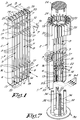
- a radiator 1 mainly consists of a heating body 2 formed of a number of pipes 3 mounted next to one another on the one hand, and of collector canalizations 4-5 which connect the above-mentioned pipes 3 on the other hand and which consist of separate and/or individual collector connections 6-7 between the respective pipes 3 which are provided on the back side 8 of the heating body 2.
- the collector connections 6-7 preferably consist of little pipes, which offers the advantage that no particular collector designs have to be developed.
- the collector connections 6-7 are preferably carried out in the shape of bends whose ends 9-10 are directed to the back sides 11 of the pipes 3 concerned.
- the bends can hereby be secured with the ends 9-10 to the back sides 11 by means of welding, soldering or such.
- the necessary corresponding openings 12 are provided in the pipes 3 which may consist of bore holes.
- radiator 1 is also provided with connecting pieces 13 and 14 which form for example an inlet and an outlet, or which are designed to be connected to other radiators.
- the bends preferably make a connection between each time two pipes 3 situated next to one another, so that the whole can be systematically connected.
- the pipes 3 are, at least in the case of a vertical erection, consecutively connected both on the top side and on the bottom side, possibly to the exception of one, two or several pipes situated on the inlet, which are not connected any further near said inlet.
- the latter is represented in figure 1, whereby the first pipe 3 is connected at the bottom, as of the connecting piece 13, to the second pipe 3, but whereby this second pipe 3 is not connected to the third pipe 3 at the bottom. In this manner is obtained that the water which is supplied via the connecting piece 13 must first rise via two pipes and can subsequently flow down again via the other pipes.
- the different openings 12 of one and the same pipe are preferably situated on top of one another, such that these openings 12, as well as the bends connecting onto them, have a maximum diameter.
- the successive collector connections 6, as well as the successive collector connections 7 are preferably also erected perpendicularly.
- a major advantage of the use of such individual collector connections 6-7 consists in that the flow pattern can be easily altered as a function of the application by providing collector connections 6-7 wherever required, without having to mount another collector for every application or for radiators with more or less pipes 3.
- the connecting piece 13 can also be provided on the top side, whereas the connecting piece 14 is situated at the bottom, or vice versa.
- the pipes 3 are preferably erected vertically and parallel in relation to one another.
- the pipes 3 are fixed to one another by means of supports 15-16 upon which they are provided. These supports 15-16 are situated on the back side 8 and preferably have positioning means and/or spacer sleeves 17 which assure the parallel mounting of the pipes 3.
- the pipes 3 can be welded onto the supports 15-16.
- the sections of the pipes 3 have converging sides, whereby these pipes converge to the front side.
- the pipes 3, as represented, have triangular sections and they are directed backward with one side, in particular the above-mentioned back side 11.
- the crosscut ends of the pipes 3 are sealed, for example by means of plates 18-19 welded onto them.
- the pipes 3 have isosceles triangular sections, whereby the base of the triangular form is directed backward.
- the shortest distance D between the pipes 3 is preferably smaller than half the dimension B of the above-mentioned base.
- the above-mentioned converging shape of the pipes 3 offers several advantages. As the pipes converge, the radiator can be easily carried out in different shapes, both flat as represented in figure 1, and bent as will be further described, but whereby a similar aspect is always obtained.
- the converging shape also offers the advantage that an optimum heat emission is obtained.
- the converging shape of the pipes 3 also offers the advantage that the distance D can be kept very short, without this having any effect on the heat emission, so that the components which are situated on the back side of the radiator, such as the collector connections 6-7, the connecting pieces 13-14 and the supports 15-16 are maximally hidden from view.
- the invention is particularly suitable to make radiators with a bent shape, in other words radiators whose front side has a bent curve.
- a radiator with a bent heating body 2 is represented as an example in figure 2, whereby the pipes 3 are erected next to one another to this aim according to a semi-cylinder.
- the pipes 3 are hereby cut at the required length and sealed at their crosscut ends by means of the above-mentioned plates 18-19.
- These supports 15-16 in this case consist of clips, formed of a semi-cylindrical part 21 and a straight part 22 which connects the ends of the semi-cylindrical part to one another.
- the collector connections 6-7 and the connecting pieces 13-14 are soldered down on the spots concerned, naturally on the back side of the radiator 1, which in this case could also be called the inner side.
- De-aerators 23 can possibly be mounted in the top ends of the pipes 3.
- the radiator 1 can also be provided with a cock 24, whose connections can possibly be hidden from view by means of a covering 25, for example a bent plate, or by mounting these components behind the pipes 3.
- a cover 26 for example made of wire netting.
- radiator 1 can also be erected and fixed in other ways.
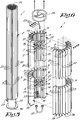
- Figure 5 shows a variant in which the pipes 3 are erected according to a cylinder, so that a radiator in the shape of a column is obtained.
- the inner side of the column should be regarded here as the "back side" of the radiator.
- the radiator 1 of figure 5 can be easily made by mounting two semi-cylindrical parts analogous to those of figure 4 against one another, as represented in figure 6, for example by means of bolts 28 with which the parts 22 directed towards one another are screwed to one another.
- a fan will be mounted in this space according to a preferred embodiment which creates a forced air flow over the pipes 3.
- a fan 29 with a built-in motor which is placed on the top support 15-16, whereby a protection is provided over this fan 29, such as a cover 26 made of wire netting or such.
- the whole can be mounted on a foot 30. Practically, this can be done by providing a number of screw blocks 31 against the back side 8 of a number of pipes 3 which can cooperate with props 32 which are part of the foot 30.
- the screw blocks 31 are provided with at least two holes 33 with internal screw thread provided on top of one another, in which bolts 34 can be screwed.
- the props 32 are made of U-shaped profiles and thus form a guide for the screw blocks 31. Further, these props 32 are provided at their top ends with a seating 35 in the shape of a recess and a bore hole 36 provided underneath it.
- bolts 34 are first screwed in the top holes 33 and the foot 30 is pushed in the heating body 2 until the bolts 34 take place in the seatings 35. Then, the bottom bolts 34 must be screwed through the bore holes 36 in the lower holes 33. Finally, all bolts 34 are tightened.
- the whole can be equipped with a cock 24, whereby the necessary connections can be hidden from view by means of a covering 25.
- the two semi-cylindrical parts of the radiator 1 can be connected in shunt as well as in series. In the latter case, they are connected by means of a connecting piece 37 as represented in figure 6 which connects the outlet of the first radiator to the inlet of the second one.
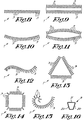
- the radiator 1 can be made in other shapes, either or not bent. Several examples thereof are represented by means of a schematic view of a crosscut face of such a radiator 1 in figures 8 to 15, whereby no collector canalizations are represented for clarity's sake.
- radiator 1 can also be mounted with the pipes 3 horizontally, whereby the collector canalizations 4-5 are then situated on the left and right hand side.
Landscapes
- Engineering & Computer Science (AREA)
- Physics & Mathematics (AREA)
- Thermal Sciences (AREA)
- Mechanical Engineering (AREA)
- General Engineering & Computer Science (AREA)
- Domestic Hot-Water Supply Systems And Details Of Heating Systems (AREA)
- Heating, Cooling, Or Curing Plastics Or The Like In General (AREA)
- Resistance Heating (AREA)
- Central Heating Systems (AREA)
Applications Claiming Priority (2)
| Application Number | Priority Date | Filing Date | Title |
|---|---|---|---|
| BE9600601A BE1010399A6 (nl) | 1996-07-02 | 1996-07-02 | Radiator voor centrale verwarming en werkwijze voor het samenstellen van dergelijke radiator. |
| BE9600601 | 1996-07-02 |
Publications (3)
| Publication Number | Publication Date |
|---|---|
| EP0816789A2 true EP0816789A2 (de) | 1998-01-07 |
| EP0816789A3 EP0816789A3 (de) | 1998-10-28 |
| EP0816789B1 EP0816789B1 (de) | 2002-06-05 |
Family
ID=3889854
Family Applications (1)
| Application Number | Title | Priority Date | Filing Date |
|---|---|---|---|
| EP97201974A Expired - Lifetime EP0816789B1 (de) | 1996-07-02 | 1997-07-01 | Heizkörper für Zentralheizung und Verfahren zu dessen Zusammenbau |
Country Status (5)
| Country | Link |
|---|---|
| EP (1) | EP0816789B1 (de) |
| AT (1) | ATE218696T1 (de) |
| BE (1) | BE1010399A6 (de) |
| DE (1) | DE69712985T2 (de) |
| ES (1) | ES2175262T3 (de) |
Cited By (2)
| Publication number | Priority date | Publication date | Assignee | Title |
|---|---|---|---|---|
| EP1970659A1 (de) * | 2007-03-05 | 2008-09-17 | DL RADIATORS S.p.A. | Heizkörper zum Beheizen eines Raums |
| WO2009132776A1 (de) * | 2008-04-29 | 2009-11-05 | Gea Air Treatment Gmbh | Wärmetauscher und konvektoreinheit aus wärmetauschern |
Family Cites Families (4)
| Publication number | Priority date | Publication date | Assignee | Title |
|---|---|---|---|---|
| DE334809C (de) * | 1921-03-19 | Schmidt Oskar | Gliederheizkoerper fuer Zentralheizung mit nach dem zu heizenden Raum einseitig ausladenden Gliedern | |
| ATE67026T1 (de) * | 1988-07-08 | 1991-09-15 | Arbonia Ag | Waschtisch mit heizkoerper. |
| CH675472A5 (en) * | 1988-07-18 | 1990-09-28 | Neotech Holding Ag | Mfg. tubular heating radiator - bends tube ends for projection welding into header bores |
| DE29603646U1 (de) * | 1996-02-28 | 1996-04-18 | Kubitza, Michael, 46236 Bottrop | Raumheizkörper einer Warmwasserheizung |
-
1996
- 1996-07-02 BE BE9600601A patent/BE1010399A6/nl not_active IP Right Cessation
-
1997
- 1997-07-01 AT AT97201974T patent/ATE218696T1/de active
- 1997-07-01 ES ES97201974T patent/ES2175262T3/es not_active Expired - Lifetime
- 1997-07-01 EP EP97201974A patent/EP0816789B1/de not_active Expired - Lifetime
- 1997-07-01 DE DE69712985T patent/DE69712985T2/de not_active Expired - Lifetime
Non-Patent Citations (1)
| Title |
|---|
| None |
Cited By (2)
| Publication number | Priority date | Publication date | Assignee | Title |
|---|---|---|---|---|
| EP1970659A1 (de) * | 2007-03-05 | 2008-09-17 | DL RADIATORS S.p.A. | Heizkörper zum Beheizen eines Raums |
| WO2009132776A1 (de) * | 2008-04-29 | 2009-11-05 | Gea Air Treatment Gmbh | Wärmetauscher und konvektoreinheit aus wärmetauschern |
Also Published As
| Publication number | Publication date |
|---|---|
| DE69712985D1 (de) | 2002-07-11 |
| EP0816789A3 (de) | 1998-10-28 |
| ES2175262T3 (es) | 2002-11-16 |
| DE69712985T2 (de) | 2003-01-02 |
| EP0816789B1 (de) | 2002-06-05 |
| BE1010399A6 (nl) | 1998-07-07 |
| ATE218696T1 (de) | 2002-06-15 |
Similar Documents
| Publication | Publication Date | Title |
|---|---|---|
| US20250137273A1 (en) | Compact Universal Gas Pool Heater And Associated Methods | |
| CN209926967U (zh) | 热交换组件、热交换器以及空调装置 | |
| JPH08261404A (ja) | 熱交換器 | |
| JP2010107151A (ja) | 冷暖房用などのパネル | |
| GB1593840A (en) | Heating apparatus | |
| US4344411A (en) | Heat exchanger for space heaters | |
| EP0816789B1 (de) | Heizkörper für Zentralheizung und Verfahren zu dessen Zusammenbau | |
| US4099555A (en) | Convector having a flattened plastic tube spiral | |
| EP0461781B1 (de) | Wärmetauscher | |
| JP4782520B2 (ja) | コンデンサのコネクタ固定構造 | |
| CN216114283U (zh) | 一种取暖器用电加热结构 | |
| US20060037734A1 (en) | Radiator for vehicle use | |
| RU2073817C1 (ru) | Отопительный радиатор | |
| US20220128243A1 (en) | Baseboard radiator | |
| EP1277015A1 (de) | Rohrhalterung | |
| KR200417942Y1 (ko) | 구별 분리형 온수분배기 | |
| GB2118706A (en) | Radiators for space heating | |
| EP1655550A1 (de) | Heizmittelverteiler für einen Plattenheizkörper | |
| CN223795520U (zh) | 安装方便的冷媒散热管组件 | |
| AU2003213465B2 (en) | Combined hot-water supply system | |
| RU2746758C1 (ru) | Конвектор напольный | |
| JPH08219589A (ja) | 凝縮器 | |
| KR20030077308A (ko) | 열교환기와 팬유니트 조립체 | |
| KR100455921B1 (ko) | 응축기 및 그 제작방법 | |
| JPH0449512Y2 (de) |
Legal Events
| Date | Code | Title | Description |
|---|---|---|---|
| PUAI | Public reference made under article 153(3) epc to a published international application that has entered the european phase |
Free format text: ORIGINAL CODE: 0009012 |
|
| AK | Designated contracting states |
Kind code of ref document: A2 Designated state(s): AT BE CH DE ES FR GB IT LI LU NL |
|
| PUAL | Search report despatched |
Free format text: ORIGINAL CODE: 0009013 |
|
| AK | Designated contracting states |
Kind code of ref document: A3 Designated state(s): AT BE CH DE DK ES FI FR GB GR IE IT LI LU MC NL PT SE |
|
| 17P | Request for examination filed |
Effective date: 19990125 |
|
| AKX | Designation fees paid |
Free format text: AT BE CH DE ES FR GB IT LI LU NL |
|
| 17Q | First examination report despatched |
Effective date: 20010227 |
|
| GRAG | Despatch of communication of intention to grant |
Free format text: ORIGINAL CODE: EPIDOS AGRA |
|
| GRAG | Despatch of communication of intention to grant |
Free format text: ORIGINAL CODE: EPIDOS AGRA |
|
| GRAH | Despatch of communication of intention to grant a patent |
Free format text: ORIGINAL CODE: EPIDOS IGRA |
|
| GRAH | Despatch of communication of intention to grant a patent |
Free format text: ORIGINAL CODE: EPIDOS IGRA |
|
| GRAA | (expected) grant |
Free format text: ORIGINAL CODE: 0009210 |
|
| PGFP | Annual fee paid to national office [announced via postgrant information from national office to epo] |
Ref country code: LU Payment date: 20020530 Year of fee payment: 6 |
|
| AK | Designated contracting states |
Kind code of ref document: B1 Designated state(s): AT BE CH DE ES FR GB IT LI LU NL |
|
| REF | Corresponds to: |
Ref document number: 218696 Country of ref document: AT Date of ref document: 20020615 Kind code of ref document: T |
|
| REG | Reference to a national code |
Ref country code: GB Ref legal event code: FG4D |
|
| REG | Reference to a national code |
Ref country code: CH Ref legal event code: EP |
|
| REF | Corresponds to: |
Ref document number: 69712985 Country of ref document: DE Date of ref document: 20020711 |
|
| REG | Reference to a national code |
Ref country code: CH Ref legal event code: NV Representative=s name: R. A. EGLI & CO. PATENTANWAELTE |
|
| ET | Fr: translation filed | ||
| REG | Reference to a national code |
Ref country code: ES Ref legal event code: FG2A Ref document number: 2175262 Country of ref document: ES Kind code of ref document: T3 |
|
| PLBE | No opposition filed within time limit |
Free format text: ORIGINAL CODE: 0009261 |
|
| STAA | Information on the status of an ep patent application or granted ep patent |
Free format text: STATUS: NO OPPOSITION FILED WITHIN TIME LIMIT |
|
| 26N | No opposition filed |
Effective date: 20030306 |
|
| PG25 | Lapsed in a contracting state [announced via postgrant information from national office to epo] |
Ref country code: LU Free format text: LAPSE BECAUSE OF NON-PAYMENT OF DUE FEES Effective date: 20030701 |
|
| REG | Reference to a national code |
Ref country code: FR Ref legal event code: ST Effective date: 20080331 |
|
| PG25 | Lapsed in a contracting state [announced via postgrant information from national office to epo] |
Ref country code: FR Free format text: LAPSE BECAUSE OF NON-PAYMENT OF DUE FEES Effective date: 20070731 |
|
| REG | Reference to a national code |
Ref country code: FR Ref legal event code: D3 |
|
| PG25 | Lapsed in a contracting state [announced via postgrant information from national office to epo] |
Ref country code: IT Free format text: LAPSE BECAUSE OF NON-PAYMENT OF DUE FEES Effective date: 20100701 |
|
| PGFP | Annual fee paid to national office [announced via postgrant information from national office to epo] |
Ref country code: FR Payment date: 20110614 Year of fee payment: 15 Ref country code: CH Payment date: 20110617 Year of fee payment: 15 |
|
| PGRI | Patent reinstated in contracting state [announced from national office to epo] |
Ref country code: IT Effective date: 20110616 |
|
| PGFP | Annual fee paid to national office [announced via postgrant information from national office to epo] |
Ref country code: BE Payment date: 20110531 Year of fee payment: 15 |
|
| PGFP | Annual fee paid to national office [announced via postgrant information from national office to epo] |
Ref country code: GB Payment date: 20110713 Year of fee payment: 15 Ref country code: AT Payment date: 20110729 Year of fee payment: 15 Ref country code: DE Payment date: 20110705 Year of fee payment: 15 Ref country code: ES Payment date: 20110830 Year of fee payment: 15 |
|
| PGFP | Annual fee paid to national office [announced via postgrant information from national office to epo] |
Ref country code: NL Payment date: 20110801 Year of fee payment: 15 Ref country code: IT Payment date: 20110704 Year of fee payment: 15 |
|
| BERE | Be: lapsed |
Owner name: *JAGA N.V. Effective date: 20120731 |
|
| REG | Reference to a national code |
Ref country code: NL Ref legal event code: V1 Effective date: 20130201 |
|
| REG | Reference to a national code |
Ref country code: CH Ref legal event code: PL |
|
| REG | Reference to a national code |
Ref country code: AT Ref legal event code: MM01 Ref document number: 218696 Country of ref document: AT Kind code of ref document: T Effective date: 20120701 |
|
| GBPC | Gb: european patent ceased through non-payment of renewal fee |
Effective date: 20120701 |
|
| REG | Reference to a national code |
Ref country code: FR Ref legal event code: ST Effective date: 20130329 |
|
| PG25 | Lapsed in a contracting state [announced via postgrant information from national office to epo] |
Ref country code: LI Free format text: LAPSE BECAUSE OF NON-PAYMENT OF DUE FEES Effective date: 20120731 Ref country code: GB Free format text: LAPSE BECAUSE OF NON-PAYMENT OF DUE FEES Effective date: 20120701 Ref country code: CH Free format text: LAPSE BECAUSE OF NON-PAYMENT OF DUE FEES Effective date: 20120731 Ref country code: NL Free format text: LAPSE BECAUSE OF NON-PAYMENT OF DUE FEES Effective date: 20130201 Ref country code: FR Free format text: LAPSE BECAUSE OF NON-PAYMENT OF DUE FEES Effective date: 20120731 Ref country code: DE Free format text: LAPSE BECAUSE OF NON-PAYMENT OF DUE FEES Effective date: 20130201 |
|
| PG25 | Lapsed in a contracting state [announced via postgrant information from national office to epo] |
Ref country code: IT Free format text: LAPSE BECAUSE OF NON-PAYMENT OF DUE FEES Effective date: 20120701 Ref country code: BE Free format text: LAPSE BECAUSE OF NON-PAYMENT OF DUE FEES Effective date: 20120731 |
|
| PG25 | Lapsed in a contracting state [announced via postgrant information from national office to epo] |
Ref country code: AT Free format text: LAPSE BECAUSE OF NON-PAYMENT OF DUE FEES Effective date: 20120701 |
|
| REG | Reference to a national code |
Ref country code: DE Ref legal event code: R119 Ref document number: 69712985 Country of ref document: DE Effective date: 20130201 |
|
| REG | Reference to a national code |
Ref country code: ES Ref legal event code: FD2A Effective date: 20131018 |
|
| PG25 | Lapsed in a contracting state [announced via postgrant information from national office to epo] |
Ref country code: ES Free format text: LAPSE BECAUSE OF NON-PAYMENT OF DUE FEES Effective date: 20120702 |