EP1970659A1 - Heizkörper zum Beheizen eines Raums - Google Patents
Heizkörper zum Beheizen eines Raums Download PDFInfo
- Publication number
- EP1970659A1 EP1970659A1 EP08003953A EP08003953A EP1970659A1 EP 1970659 A1 EP1970659 A1 EP 1970659A1 EP 08003953 A EP08003953 A EP 08003953A EP 08003953 A EP08003953 A EP 08003953A EP 1970659 A1 EP1970659 A1 EP 1970659A1
- Authority
- EP
- European Patent Office
- Prior art keywords
- radiator
- heating
- fins
- previous
- room according
- Prior art date
- Legal status (The legal status is an assumption and is not a legal conclusion. Google has not performed a legal analysis and makes no representation as to the accuracy of the status listed.)
- Withdrawn
Links
- 238000010438 heat treatment Methods 0.000 title claims abstract description 77
- 239000012530 fluid Substances 0.000 claims abstract description 31
- 229910000831 Steel Inorganic materials 0.000 claims 1
- 239000010959 steel Substances 0.000 claims 1
- 230000001747 exhibiting effect Effects 0.000 abstract description 2
- 230000013011 mating Effects 0.000 description 7
- 230000009977 dual effect Effects 0.000 description 3
- 230000000694 effects Effects 0.000 description 3
- 239000002184 metal Substances 0.000 description 2
- 230000005540 biological transmission Effects 0.000 description 1
- 239000000463 material Substances 0.000 description 1
- 238000000465 moulding Methods 0.000 description 1
- 238000003466 welding Methods 0.000 description 1
Images

Classifications
-
- F—MECHANICAL ENGINEERING; LIGHTING; HEATING; WEAPONS; BLASTING
- F28—HEAT EXCHANGE IN GENERAL
- F28D—HEAT-EXCHANGE APPARATUS, NOT PROVIDED FOR IN ANOTHER SUBCLASS, IN WHICH THE HEAT-EXCHANGE MEDIA DO NOT COME INTO DIRECT CONTACT
- F28D1/00—Heat-exchange apparatus having stationary conduit assemblies for one heat-exchange medium only, the media being in contact with different sides of the conduit wall, in which the other heat-exchange medium is a large body of fluid, e.g. domestic or motor car radiators
- F28D1/02—Heat-exchange apparatus having stationary conduit assemblies for one heat-exchange medium only, the media being in contact with different sides of the conduit wall, in which the other heat-exchange medium is a large body of fluid, e.g. domestic or motor car radiators with heat-exchange conduits immersed in the body of fluid
- F28D1/04—Heat-exchange apparatus having stationary conduit assemblies for one heat-exchange medium only, the media being in contact with different sides of the conduit wall, in which the other heat-exchange medium is a large body of fluid, e.g. domestic or motor car radiators with heat-exchange conduits immersed in the body of fluid with tubular conduits
- F28D1/053—Heat-exchange apparatus having stationary conduit assemblies for one heat-exchange medium only, the media being in contact with different sides of the conduit wall, in which the other heat-exchange medium is a large body of fluid, e.g. domestic or motor car radiators with heat-exchange conduits immersed in the body of fluid with tubular conduits the conduits being straight
- F28D1/0535—Heat-exchange apparatus having stationary conduit assemblies for one heat-exchange medium only, the media being in contact with different sides of the conduit wall, in which the other heat-exchange medium is a large body of fluid, e.g. domestic or motor car radiators with heat-exchange conduits immersed in the body of fluid with tubular conduits the conduits being straight the conduits having a non-circular cross-section
- F28D1/05366—Assemblies of conduits connected to common headers, e.g. core type radiators
-
- F—MECHANICAL ENGINEERING; LIGHTING; HEATING; WEAPONS; BLASTING
- F28—HEAT EXCHANGE IN GENERAL
- F28F—DETAILS OF HEAT-EXCHANGE AND HEAT-TRANSFER APPARATUS, OF GENERAL APPLICATION
- F28F1/00—Tubular elements; Assemblies of tubular elements
- F28F1/10—Tubular elements and assemblies thereof with means for increasing heat-transfer area, e.g. with fins, with projections, with recesses
- F28F1/12—Tubular elements and assemblies thereof with means for increasing heat-transfer area, e.g. with fins, with projections, with recesses the means being only outside the tubular element
-
- F—MECHANICAL ENGINEERING; LIGHTING; HEATING; WEAPONS; BLASTING
- F28—HEAT EXCHANGE IN GENERAL
- F28D—HEAT-EXCHANGE APPARATUS, NOT PROVIDED FOR IN ANOTHER SUBCLASS, IN WHICH THE HEAT-EXCHANGE MEDIA DO NOT COME INTO DIRECT CONTACT
- F28D21/00—Heat-exchange apparatus not covered by any of the groups F28D1/00 - F28D20/00
- F28D2021/0019—Other heat exchangers for particular applications; Heat exchange systems not otherwise provided for
- F28D2021/0035—Other heat exchangers for particular applications; Heat exchange systems not otherwise provided for for domestic or space heating, e.g. heating radiators
-
- F—MECHANICAL ENGINEERING; LIGHTING; HEATING; WEAPONS; BLASTING
- F28—HEAT EXCHANGE IN GENERAL
- F28F—DETAILS OF HEAT-EXCHANGE AND HEAT-TRANSFER APPARATUS, OF GENERAL APPLICATION
- F28F2215/00—Fins
- F28F2215/06—Hollow fins; fins with internal circuits
-
- F—MECHANICAL ENGINEERING; LIGHTING; HEATING; WEAPONS; BLASTING
- F28—HEAT EXCHANGE IN GENERAL
- F28F—DETAILS OF HEAT-EXCHANGE AND HEAT-TRANSFER APPARATUS, OF GENERAL APPLICATION
- F28F2215/00—Fins
- F28F2215/10—Secondary fins, e.g. projections or recesses on main fins
Definitions
- the present invention relates to a radiator for heating a room, in particular but not necessarily for living use, of the type comprising a plurality of heating elements (tubular or stamped plate) connected to a delivery header and a return header for the circulation of a carrier fluid, and fins for optimising the convective heat exchange with the room.
- a radiator for heating a room in particular but not necessarily for living use
- the type comprising a plurality of heating elements (tubular or stamped plate) connected to a delivery header and a return header for the circulation of a carrier fluid, and fins for optimising the convective heat exchange with the room.
- such fins are provided with dry convective surfaces generally obtained from "frets" of stamped plate welded to the heating elements, made of metal as well.
- the limit of the prior art consists in that if on the one end, that is, the welding one, such fins have almost the same temperature, by contact, on the wet metal, on the other one, that is, towards the opposite end, by the effect of heat transmission especially on walls thins like these ones, the temperature is considerably and progressively lower. It is clear that the limits wet exchange surface affects the heat exchange by irradiation. Moreover, the temperature gradient that sets along the fins negatively affects also the heat exchange by natural convection, limiting the "chimney effect". The technical task of the present invention therefore is to provide a radiator for heating a room which should allow eliminating the aforementioned technical disadvantages of the prior art.
- an object of the invention is to provide a radiator for heating a room which should optimise the heat exchange both by irradiation and by natural convection.
- a radiator for heating a room according to claim 1 An important aspect of the invention consists exactly in making a radiator wherein the traditional "dry” fine are replaced by “wet” fins wherein the carrier fluid, the same used to heat the radiator itself, circulates. These fins may be obtained from “closed” variedly shaped tubular profiles, from “open” variedly shaped section bar elements, or by sheet moulding/drawing. Such fins may be located inside and/or behind (wall side) one or more radiator walls, whether it is tubular or of stamped plate, but also at the front (that is, on the exposed side of the radiator).
- Such fins may be applied to the heating elements or be shaped therewith.
- fins may be applied to plate or tubular radiator models, whether the heating elements of the latter are arranged vertically or horizontally relative to the natural vertical arrangement thereof.
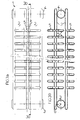
- radiator for heating a room in a building particularly but not necessarily for living use, globally indicated with reference numeral 1.
- Radiator 1 comprises a plurality of heating elements 2 connected to a delivery header 3 and a return header 4 for the circulation of a carrier fluid.
- radiator 1 comprises fins 5 for optimising the heat exchange with the room, exhibiting wet inside surfaces wherein said carrier fluid circulates.
- Fins 5 are channel-shaped for delimiting, alone and/or in cooperation with the heating elements 2, flowing channels for the carrier fluid internally, and for air externally.
- Fins 5 therefore are in fluid communication with the heating elements 2 in turn in fluid communication, as said, with the delivery header 3 and the return header 4.
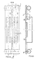
- a heating element 2 and a fin 5 are shaped in a single "T" tubular profile with closed section and closed ends. More precisely, there are four “T" tubular profiles connecting the delivery header 3 to the return header 4, whereof two are arranged at a front wall of radiator 1 and two are arranged at a back wall of radiator 1.
- the "T" tubular profiles, in the portion defining the base of fin 5, are welded to the delivery 3 and return 4 headers they are in fluid communication with, thanks to overlapped holes 6 and 7 provided in the mating zone thereof.
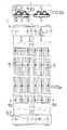
- a heating element 2 and two fins 5 are shaped in a single dual "T” (TT) tubular profile with closed section and closed ends. More precisely, there are four dual “T” tubular profiles connecting the delivery header 3 to the return header 4, whereof two are arranged at a front wall of radiator 1 and two are arranged at a back wall of radiator 1. Dual "T" tubular profiles, in the portion defining the base of fin 5, are welded to the delivery 3 and return 4 headers they are in fluid communication with, thanks to the overlapped holes 6 and 7 provided in the mating zone thereof. With reference to figures 3a and 3b , two heating elements 2 are provided at a front wall of radiator 1 and two heating elements 2 at a back wall of radiator 1.
- Fins 5 are comprised of "C" tubular profiles with closed section and open ends.
- a first series of fins 5 is applied bridge-wise between the front surface of the two front heating elements 2
- a second series of fins 5 is applied bridge-wise between the front surface of the two back heating elements 2 in the space comprised between the two front heating elements 2 and the two back heating elements 2
- a third series of fins 5 is applied bridge-wise between the back surface of the two back heating elements 2
- each open end of each fin 5 is inserted through the wall thickness of the corresponding heating element 2 with which it exhibits an intersection portion.
- the heating elements 2 at the bases thereof are welded to the delivery 3 and return 4 headers they are in fluid communication with, thanks to the overlapped holes 6 and 7 provided in the mating zone thereof.
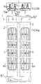
- two heating elements 2 are provided at a front wall of radiator 1.
- Fins 5 are comprised of "C" tubular profiles with closed section and open ends. A first series of two fins 5 is applied to the back surface of one of the two heating elements 2, whereas a second series of two fins 5 is applied to the back surface of the other heating element 2. To ensure fluid communication between each fin 5 and the heating element 2 it is applied to, each open end 8 of each fin 5 is inserted through the wall thickness of the heating element 2 with which it exhibits an intersection portion.
- End 8 of fin 5 lies on an oblique plane relative to the longitudinal axis 9 of the fin itself.
- a portion of edge 10 of base 8 of fin 5 is juxtaposed to a portion of edge 11 of the opening of the heating element 2 wherein fin 5 is inserted so that a seating surface is created for the passage of the carrier fluid from the heating element 2 to fin 5.
- the opposite side of base 8 acts as deflector for the fluid from element 2 to fin 5.
- the heating elements 2 at the bases thereof are welded to the delivery 3 and return 4 headers they are in fluid communication with, thanks to the overlapped holes 6 and 7 provided in the mating zone thereof.
- two heating elements 2 are provided at a front wall of radiator 1.
- Fins 5 are comprised of "W" tubular profiles with closed section and closed ends.
- a first fin 5 is applied to the back surface of one of the two heating elements 2, whereas a second fin 5 is applied to the back surface of the other heating element 2.
- Each fin 5 is welded to the corresponding heating element 2 it is in fluid communication with, thanks to overlapped holes 12 and 13 provided in the mating zone thereof.
- Each heating element 2 is welded to the delivery 3 and return 4 headers it is in fluid communication with, thanks to overlapped holes 6 and 7 provided in the mating zone thereof.
- two heating elements 2 are provided at a front wall of radiator 1.
- Fins 5 are comprised of open section bars.
- a first fin 5 is applied to the back surface of one of the two heating elements 2, whereas a second fin 5 is applied to the back surface of the other heating element 2.
- Each fin 5 is welded to the corresponding heating element 2.
- fin 5 is in fluid communication with the corresponding heating element 2 through holes 15a and 15b obtained through the thickness of the wall portion of the heating element 2.
- Each heating element 2 is welded to the delivery 3 and return 4 headers it is in fluid communication with, thanks to overlapped holes 6 and 7 provided in the mating zone thereof.
- fins 5, in any particular embodiment of the invention may be arranged at a back wall of the radiator (as shown, for example, in the embodiments of figure 4a , 5a , 6a ) and/or at an inner wall of the radiator (as shown, for example, in the embodiment of figure 3a, 3b ) and/or also at a front wall of said radiator (as shown, for example, in the embodiment of figure 3b ).
- Fin 5 may be comprised in general of a tubular profile with circular or polygonal closed section having open or closed ends, or of a channel-shaped profile with open section cooperates with the heating element 2 or the heating elements 2 it is associated to for defining flowing channels for the carrier fluid.
- radiator clearly appears from what described and illustrated: the circulation of the carrier fluid that sets in the radiator besides the heating elements 2 also impinges the inner surfaces of the fins 5 that are in fluid communication with the heating elements, thus bringing all the advantages mentioned above.
Landscapes
- Engineering & Computer Science (AREA)
- Physics & Mathematics (AREA)
- Thermal Sciences (AREA)
- Mechanical Engineering (AREA)
- General Engineering & Computer Science (AREA)
- Geometry (AREA)
- Transition And Organic Metals Composition Catalysts For Addition Polymerization (AREA)
- Materials For Medical Uses (AREA)
- Domestic Hot-Water Supply Systems And Details Of Heating Systems (AREA)
Applications Claiming Priority (1)
| Application Number | Priority Date | Filing Date | Title |
|---|---|---|---|
| IT000440A ITMI20070440A1 (it) | 2007-03-05 | 2007-03-05 | Radiatore per il risaldamento di un ambiente |
Publications (1)
| Publication Number | Publication Date |
|---|---|
| EP1970659A1 true EP1970659A1 (de) | 2008-09-17 |
Family
ID=39472516
Family Applications (1)
| Application Number | Title | Priority Date | Filing Date |
|---|---|---|---|
| EP08003953A Withdrawn EP1970659A1 (de) | 2007-03-05 | 2008-03-04 | Heizkörper zum Beheizen eines Raums |
Country Status (2)
| Country | Link |
|---|---|
| EP (1) | EP1970659A1 (de) |
| IT (1) | ITMI20070440A1 (de) |
Citations (10)
| Publication number | Priority date | Publication date | Assignee | Title |
|---|---|---|---|---|
| GB191126628A (en) * | 1911-11-28 | 1912-03-28 | Wilhelm Siller | Improvements in and relating to Radiators for Heating Buildings and the like. |
| US1753318A (en) * | 1925-05-12 | 1930-04-08 | Alton H Greeley | Heat-exchange apparatus |
| GB1313438A (en) * | 1971-09-06 | 1973-04-11 | Miles D | Convector space heating or cooling apparatus |
| DE2440184A1 (de) * | 1974-08-22 | 1976-03-04 | Roentgen & Co | Ausgestaltung eines gliedes aus stahlblech fuer einen heizungsradiator |
| GB2094966A (en) * | 1981-03-12 | 1982-09-22 | Runtal Holding Co Sa | Radiator with parallel flat tubes |
| CH673421A5 (en) * | 1987-06-26 | 1990-03-15 | Runtal Holding Co Sa | Heating radiator production method - presses flat tubes inwards at curved edges for pressure-welding to manifolds |
| DE9207082U1 (de) * | 1991-06-25 | 1992-08-13 | Runtal Holding Co., S.A., Glarus | Heizrohr zur Bildung einer Heizwand |
| EP0816789A2 (de) * | 1996-07-02 | 1998-01-07 | Jaga, naamloze vennootschap | Heizkörper für Zentralheizung und Verfahren zu dessen Zusammenbau |
| EP0918202A1 (de) * | 1997-11-24 | 1999-05-26 | Arbonia Ag | Röhrenheizkörper |
| WO2000047940A1 (en) * | 1999-02-12 | 2000-08-17 | Baggrave Ltd. | A radiator |
-
2007
- 2007-03-05 IT IT000440A patent/ITMI20070440A1/it unknown
-
2008
- 2008-03-04 EP EP08003953A patent/EP1970659A1/de not_active Withdrawn
Patent Citations (10)
| Publication number | Priority date | Publication date | Assignee | Title |
|---|---|---|---|---|
| GB191126628A (en) * | 1911-11-28 | 1912-03-28 | Wilhelm Siller | Improvements in and relating to Radiators for Heating Buildings and the like. |
| US1753318A (en) * | 1925-05-12 | 1930-04-08 | Alton H Greeley | Heat-exchange apparatus |
| GB1313438A (en) * | 1971-09-06 | 1973-04-11 | Miles D | Convector space heating or cooling apparatus |
| DE2440184A1 (de) * | 1974-08-22 | 1976-03-04 | Roentgen & Co | Ausgestaltung eines gliedes aus stahlblech fuer einen heizungsradiator |
| GB2094966A (en) * | 1981-03-12 | 1982-09-22 | Runtal Holding Co Sa | Radiator with parallel flat tubes |
| CH673421A5 (en) * | 1987-06-26 | 1990-03-15 | Runtal Holding Co Sa | Heating radiator production method - presses flat tubes inwards at curved edges for pressure-welding to manifolds |
| DE9207082U1 (de) * | 1991-06-25 | 1992-08-13 | Runtal Holding Co., S.A., Glarus | Heizrohr zur Bildung einer Heizwand |
| EP0816789A2 (de) * | 1996-07-02 | 1998-01-07 | Jaga, naamloze vennootschap | Heizkörper für Zentralheizung und Verfahren zu dessen Zusammenbau |
| EP0918202A1 (de) * | 1997-11-24 | 1999-05-26 | Arbonia Ag | Röhrenheizkörper |
| WO2000047940A1 (en) * | 1999-02-12 | 2000-08-17 | Baggrave Ltd. | A radiator |
Also Published As
| Publication number | Publication date |
|---|---|
| ITMI20070440A1 (it) | 2008-09-06 |
Similar Documents
| Publication | Publication Date | Title |
|---|---|---|
| CN109883241B (zh) | 热交换组件、热交换器以及空调装置 | |
| US20060162917A1 (en) | Heat exchanger | |
| EP2233874B1 (de) | Wärmetauscher | |
| JP6330577B2 (ja) | フィン・アンド・チューブ型熱交換器 | |
| CN105352345B (zh) | 微通道换热器及其空调器 | |
| US20060131009A1 (en) | Heat exchanger, especially for vehicles | |
| KR20170053676A (ko) | 열교환기를 위한 상변화 물질의 저장소를 갖는 튜브 | |
| US20080308264A1 (en) | Multiple Flow Heat Exchanger | |
| EP2447660A2 (de) | Wärmetauscher und zugehöriges Mikrokanalrohr | |
| CN113357937B (zh) | 翅片及换热器 | |
| KR101184208B1 (ko) | 열교환기 | |
| CN217635915U (zh) | 热交换器和热交换单元 | |
| KR101207340B1 (ko) | 판열교환핀 및 지그재그구부림튜브가 구비된 열교환기 및 그의 제조방법 | |
| US3106958A (en) | Heat exchanger | |
| KR102025459B1 (ko) | 열교환기 수단용 배관 요소 | |
| CN110094901B (zh) | 一种微通道换热器 | |
| JP2018105509A (ja) | 熱交換器 | |
| KR100376653B1 (ko) | 열교환기용 코어 | |
| KR101543522B1 (ko) | 열교환기용 납작관 및 이를 구비하는 열교환기 | |
| US1937713A (en) | Heat transfer apparatus | |
| EP1010956A1 (de) | Verflüssiger für Kühlschrank, Gefrierschrank, oder deren Kombination | |
| KR102350040B1 (ko) | 열교환기용 튜브 및 이를 포함하는 열교환기 | |
| JP2015081744A (ja) | 熱交換器 | |
| KR100812497B1 (ko) | 고압 열교환기의 헤더 | |
| EP1914499A1 (de) | Wärmetauscher mit schräg gestellten Rohren |
Legal Events
| Date | Code | Title | Description |
|---|---|---|---|
| PUAI | Public reference made under article 153(3) epc to a published international application that has entered the european phase |
Free format text: ORIGINAL CODE: 0009012 |
|
| AK | Designated contracting states |
Kind code of ref document: A1 Designated state(s): AT BE BG CH CY CZ DE DK EE ES FI FR GB GR HR HU IE IS IT LI LT LU LV MC MT NL NO PL PT RO SE SI SK TR |
|
| AX | Request for extension of the european patent |
Extension state: AL BA MK RS |
|
| 17P | Request for examination filed |
Effective date: 20090317 |
|
| AKX | Designation fees paid |
Designated state(s): AT BE BG CH CY CZ DE DK EE ES FI FR GB GR HR HU IE IS IT LI LT LU LV MC MT NL NO PL PT RO SE SI SK TR |
|
| RAP1 | Party data changed (applicant data changed or rights of an application transferred) |
Owner name: DL RADIATORS S.R.L. |
|
| 17Q | First examination report despatched |
Effective date: 20161202 |
|
| STAA | Information on the status of an ep patent application or granted ep patent |
Free format text: STATUS: THE APPLICATION IS DEEMED TO BE WITHDRAWN |
|
| 18D | Application deemed to be withdrawn |
Effective date: 20170613 |