EP0816799A2 - Mesure de la condition d'un pneumatique - Google Patents
Mesure de la condition d'un pneumatique Download PDFInfo
- Publication number
- EP0816799A2 EP0816799A2 EP97304630A EP97304630A EP0816799A2 EP 0816799 A2 EP0816799 A2 EP 0816799A2 EP 97304630 A EP97304630 A EP 97304630A EP 97304630 A EP97304630 A EP 97304630A EP 0816799 A2 EP0816799 A2 EP 0816799A2
- Authority
- EP
- European Patent Office
- Prior art keywords
- tyre
- radiation
- tread
- respect
- vehicle
- Prior art date
- Legal status (The legal status is an assumption and is not a legal conclusion. Google has not performed a legal analysis and makes no representation as to the accuracy of the status listed.)
- Withdrawn
Links
Images


Classifications
-
- G—PHYSICS
- G01—MEASURING; TESTING
- G01B—MEASURING LENGTH, THICKNESS OR SIMILAR LINEAR DIMENSIONS; MEASURING ANGLES; MEASURING AREAS; MEASURING IRREGULARITIES OF SURFACES OR CONTOURS
- G01B11/00—Measuring arrangements characterised by the use of optical techniques
- G01B11/22—Measuring arrangements characterised by the use of optical techniques for measuring depth
Definitions
- This invention relates to a method and apparatus for tyre condition assessment which is particularly but not exclusively applicable to automotive vehicles.
- An example of the application of the invention is a method and apparatus which could be incorporated into automotive wheel balance or brake testing equipment so that a simultaneous or contemporaneous assessment of tyre tread and sidewall and other tyre condition factors may be made when other wheel tests are performed on a vehicle.
- the invention is also applicable to test equipment in the form, for example, comprising a drive-on ramp applicable to road side testing of a vehicle tyre in situ, without dismounting from a vehicle. Such applications of the invention would be suitable for law enforcement and regulation compliance authorities and their mobile personnel.
- a further application relates to test equipment used by commercial roadside test operations, particularly those specialising in rapid test services.
- the invention also provides a convenient and economical means for determining proper positional alignment of a wheel with respect to photometric or other tyre assessment apparatus, by use of data derivable from the apparatus without the need for provision of any significant further hardware.
- the invention also provides a simple abutment system for defining proper proximity of a tyre or other article under test with respect to a window of the apparatus, through which the radiation for analysis proceeds.
- An important aspect of the invention relates to systems for mounting apparatus for tyre tread assessment in relation to a vehicle tyre for tread and/or other determination purposes.
- This aspect of the invention is concerned with the fact that roller systems for rotating a vehicle wheel for test purposes can be relatively highly costly in terms of original equipment costs and installation, and yet there is a need for an ability to carry out roadside vehicle wheel tests on a rapid and easily carried-out basis at a chosen roadside location. A method and apparatus capable of offering such a facility would be of considerable utility.
- Known systems in relation to tyre tread assessment include the usual manual measurement techniques including the use of tread depth gauges for insertion into the tread, and the assessment of tread wear by image analysis of a track after paint-treatment of the tread.
- a laser sensor is utilised in relation to a tyre which is rotated while the laser sensor is mechanically scanned across the lateral width of the tyre tread, being carried on a carriage which can reciprocate across the tyre width on slide rods or bars. By virtue of the lateral motion of the carriage, the single laser point is mechanically scanned across the tyre.
- Such an arrangement is subject to significant shortcomings in terms of the ability of the apparatus to provide an acceptable range of tread determinations on a given wheel within the short period of time available for a roadside test.
- the system inevitably is subject to the mechanical limitations of the scanning mechanism for the laser point source whereby the time implications of a complete scanning operation for a single wheel become unacceptable, and some means is needed to enable a substantially greater rate of tread assessment in order to provide a realistic and practical form of apparatus.
- DE 4316984 Al Mercedes
- DE 4316984 Al a system for automatic measurement of tyre profile in which the profile is measured along a line across the rolling direction of the tyre by a traversing measuring head using a contactless optical triangulation method.
- This system is likewise subject to the performance shortcomings of the previously described reference.
- GB 2 241 061A a structured light scanning system for use in automotive service equipment in which a laser source directs a beam of known shape onto a wheel rim/tyre assembly so as to form a light stripe thereon.
- the stripe 22 of light impinges the tyre/rim assembly 21/19 and an array of sensing cells are excited.
- Pixels 52b are raised with respect to their neighbours and correspond to the valve stem 27 on the rim.
- Pixels 53b on the sensing cells correspond to the bump in the light stripe 22 where it intersects the periphery of the rim 19 of the wheel.
- the system is particularly applicable to determination of tyre/rim assembly balance, runout and alignment or brake surface planarity and smoothness determinations.
- the system of the GB 061A specification is not adapted to be able to provide tyre tread determinations, particularly with respect to tread profile and tread depth across the width of the wheel.
- An object of the present invention is to provide a method and apparatus for tyre tread assessment offering improvements in relation to the shortcomings of the prior art discussed above and/or improvements generally.
- a method and apparatus in which, by use of a radiation source and a radiation detector and associated signal processing apparatus, there can be obtained a read-out providing a direct measure of both tread depth and tread pattern, whereby a determination can be made of over/under inflation practices in relation to the history of the tyre, and a corresponding measure obtained of potentially present wheel alignment problems.
- the embodiment is readily adapted for tyre sidewall condition assessment by suitable re-positioning of the radiation source so as to be directed generally axially of the tyre, instead of radially, and towards the sidewall thereof.
- the radiation source emits a broad band beam of light which impinges on the full width of the tyre under test.
- the tyre illumination footprint is a regular well-defined zone, for example a line or other shape or pattern, with a uniform light intensity.
- the physical dimensions of a typical embodiment are shown in Fig 4.
- a laser energy source is utilised and tread depth is analysed on the basis of the laser image displacement as between the tread surface and tread bottom images.
- tread depth is analysed on the basis of the laser image displacement as between the tread surface and tread bottom images.
- the radiation source is arranged to apply the radiation to the tyre in a direction which is generally slightly offset from radially with respect to the tyre, and in a stripe or band or line across at least a portion of the lateral width of the tyre at a given peripheral location thereon.
- the radiation detector receives radiation from the tyre from across at least said portion of the lateral width thereof, so as to provide a measure of tread characteristics across said lateral width at said peripheral location by virtue of image displacement or offset.
- An analogous approach is adopted for assessment of tyre sidewall and other tyre structure or characteristics by adopting an image displacement technique for identification of sidewall and other structural discontinuities in the tyre.
- the apparatus and method are able to make tyre tread and sidewall determinations at very substantially greater rates than has been possible with the scanning type apparatus of the prior systems reviewed above.
- the line of radiation is able to provide a tyre tread or sidewall image indicative of tread bottom and tread top or sidewall protuberances relative displacement across the lateral width of the tyre or of its sidewall, relatively instantaneously.
- the radiation source is a laser source and the method comprises the step of causing the radiation detector to detect the image displacement produced by the laser beam as between the base and the top of the tread, as a measure of tread depth across at least a portion of the lateral width of the tyre.
- the use of a laser source enables a more effective determination of the laterally-extending tread profile at a particular peripheral location on the tyre, so that the image provides a measure of tread depth and tread profile.
- this laser energy using embodiment by performing tyre tread image and thus tyre tread profile determinations at two or more locations around the periphery of a tyre there is developed a profile of the tyre enabling an overall assessment of its state of wear to be made. These determinations may be made at a series of locations around the tyre and/or during rotation of the tyre. The approach is the same for sidewall and other tyre structural determinations.
- the method and apparatus requires very little modification from that described above for tyre tread assessment. Indeed, the apparatus requires only to be re-positioned in relation to the generally axially-facing tyre side wall surface so that a profile of this can be obtained and thus the presence or otherwise of discontinuities in the sidewall profile can be identified.
- the apparatus or module which contains the laser or other radiation source and the corresponding radiation sensor is located in front of or behind the tyre, or indeed to one side of it, not directly beneath it, there is no tendency at all for dirt and dust and water, or any of these, to fall onto or otherwise reach the apparatus during the test.
- the test is performed in a non-contact manner at a "clean" location in front of or behind the tyre - although the location is not in exact radial alignment with the tread of the tyre where the laser line contacts it.
- an important aspect of the embodiments concerns the facility to perform tests which require rotation of the wheel/tyre assembly without the need to provide roller means.
- rotation of the wheel/tyre assembly is achieved, for example at a roadside location, while performing tyre tread and sidewall or other tyre condition tests, in a simple manner.
- the tyre tread determination apparatus is supported from the structure of the vehicle on which the tyre in question is mounted so that the step of making the necessary determinations of tyre data can be made either during movement of the vehicle, or after such movement.
- the apparatus employed for supporting the tyre condition assessment unit is mounted on the vehicle by means of disengageable mounting means, so that the unit can be readily mounted and dismounted before and after the tests.
- disengageable mounting means is a suction unit which is manually operable, for example by means of a lever, so as to hold itself by suction to a smooth part of the vehicle's surface, for example any convenient part of the painted body of the vehicle.
- two or more such suction units would be provided together with an adjustable support frame or arm depending therefrom so that, once the suction units have been applied to a convenient part of the vehicle's body, the tyre tread unit can then be readily located alongside the tyre at a suitable location. Then, tread determinations can be made in sequence as the vehicle is moved forwards or rearwards, without any need to remove the wheel in question. Roadside tests can thereby be made quite readily provided a short stretch of suitable road or track is available for the purpose.
- any unit or apparatus requiring two or more determinations to be made of characteristics of a wheel and/or tyre assembly could be mounted in relation to a vehicle wheel in this way, and thus this aspect of the invention is not limited to utility in relation to tyre condition assessment.
- the embodiments of the invention provide a non-contact method of measuring tyre condition and characteristics including tread depth and pattern, and sidewall condition, and which can readily be incorporated with apparatus measuring tyre pressures (in accordance with the subject matter disclosed in our above-mentioned European application) and which itself uses a laser beam or stripe and related imaging optics.
- apparatus measuring tyre pressures in accordance with the subject matter disclosed in our above-mentioned European application
- a unit is mounted so that several segments of the tyre tread, within a complete revolution of the tyre, can be assessed and recorded and processed to provide a measure of tyre condition, including tyre pressure.
- the composite system permits the provision of a wide range of diagnostic information including not only tyre tread depth but also aspects of wheel alignment, these latter being available in accordance with matter disclosed in our co-pending European application number EP 96306971.1 (our reference P52765EP/Case 13).
- EP 96306971.1 our reference P52765EP/Case 13.
- a further aspect of the invention relates to the provision of means for determining the proper positional relationship between a tyre to be tested and the tyre assessment apparatus.
- a method of photometric or other tyre assessment by photometric or other incident energy analysis as defined in claims 13 to 15, and the corresponding apparatus claims 28 to 30.
- a method, and corresponding apparatus in which the positional relationship between a tyre under test and the apparatus is determined by employing as a reference base for positional analysis of the tyre with respect to the apparatus, a reflected portion of the incident energy employed for analysis of the tyre itself.
- the reflected portion of the energy is obtained by analysis of the internally reflected energy produced by an energy-transmitting surface in the apparatus, namely the external window thereof.
- the energy employed is in the form of a band or stripe or line, as applied to the tyre, and accordingly this energy format produces a corresponding reference band or line or stripe as an internal reflection from the internal surface of the window of the apparatus, which is at a known attitude with respect to the apparatus.
- the internally reflected radiation produces, in this example, a level reference base line which can be compared in attitude with the notionally vertical edge surfaces of the tyre in order to determine whether the latter is correctly aligned with respect to the apparatus about its steering axes. If a correction is needed, this can be achieved either by physically moving the apparatus or the tyre, or by a corresponding computational adjustment provided by the apparatus software.
- the apparatus is installed as garage or service station equipment then it may well be convenient to provide a roller system for rotation of the vehicle tyre during test, and thus the vehicle would be driven onto a simple roller system suitably positioned in relation to the tyre scanning apparatus.
- a modification envisages the provision of twin roller systems for simultaneous engagement with both front or both rear wheels of a vehicle, thereby achieving basic alignment of the vehicle with the tyre test apparatus. In this way, the feature of checking proper positional alignment of the wheel with respect to the apparatus becomes a refinement for fine-tuning the positional relationship.
- apparatus 10 for tyre tread assessment comprises a rotary mounting 12 for a tyre 14 to be tested.
- the mounting 12 in this embodiment is, merely by way of example, in the form of wheel balancer apparatus 16 which may be of conventional form and provides a driven axle 18 on which tyre 14 is mounted via its associated wheel 20 for tyre tread assessment purposes in accordance with the present invention.
- radiation source 22 emits a regular well-defined line of light having a uniform intensity.
- Physical dimensions are provided for the embodiment of Fig 4 and can be adapted to the corresponding layout of the present embodiment.
- Signal processing apparatus 26 is coupled to a visual display unit 30 providing an output trace 32 as shown in Fig 6. This trace represents the tread pattern at location 34 in Fig 5 at which radiation 28 is incident upon the tyre 14. Signal processing apparatus 26 provides an intensity analysis function in combination with the radiation detector 24 whereby the trace 32 provides a depth and position representation of the tread patterns 36,38 and 40.
- Radiation source 22 comprises a quartz halogen lamp coupled to a light guide producing the above-defined line emission having uniform light intensity.
- a laser source may be preferred in particular applications, and such an embodiment is described below with reference to Fig 7 of the drawings.
- Radiation detector 24 comprises an array of detector elements comprising a minimum of 375 such elements, having regard to a minimum tyre tread groove width of 2 millimetres and a requirement for a minimum of 3 pixels in each groove.
- the line width of the beam of incident radiation on the tyre should be less than 2 millimetres.
- the analogue output of detector 24 (in the range of 0 to 5 volts) is processed at 26 and displayed at 30.
- a scanning rate of from 15 to 25 line readings per tyre revolution, preferably 20, are considered sufficient for analysis purposes.
- the minimum scan rate for the array of detector elements is 15 hertz per line of detectors.
- roller brake system 42 in which rollers 44, 46 engage tyre 14 and radiation source 22 and radiation detector 24 are disposed as previously, and are likewise in association with signal processing apparatus 26 and visual display unit 30.
- This embodiment operates substantially in the same manner as the embodiments of Figs 1 and 2, yielding similar detector output traces as discussed above.
- Fig 4 shows relevant dimensional data for this embodiment, the dimensions being defined with respect to a base plate 48 on which the radiation source and detector are mounted.
- the size of the rollers used in this embodiment is dependent on tyre size and weight of vehicle. Relevant dimensional data is indicated in Fig 4.
- Fig 4 there is shown in Fig 4 in addition to the tyre 14, rollers 44, 46 and base plate 48, an idler roller 50 and a static support bar 52.
- idler roller 50 and bar 52 are raised by a spring (not shown) and the arrangement is such that the rise of these parts above a defined level triggers a safety cut-out switch isolating the electricity supply to the motors for rollers 44 and 46.
- the radiation detector 24, providing a light intensity detection function is replaced by a two-dimensional imaging camera.
- the radiation source 22 in the embodiment of Fig 4 (not seen in Fig 4 but described above in relation to Figs 1 and 3) is replaced by a corresponding light source providing a uniformly illuminated patch on the tyre 14.
- the imaging camera produces an electrical signal output based upon the secondary image produced in the camera by the incident radiation focused upon an array of light sensitive elements disposed in rows.
- the output of these elements may be analysed in rows to produce a tyre tread depth display corresponding to that shown in Fig 6.
- the output of the two-dimensional imaging camera is connected to the signal processing apparatus 26 as in the previous embodiments, so that this embodiment differs from these substantially only in the construction and arrangement of the radiation source and radiation detector.
- the two-dimensional imaging camera does not itself perform an image analysis function.
- the image data from the camera is signal-processed at 26, for example by analysis of the data from rows of light sensitive elements, to produce a tyre tread depth display, for example as shown in Fig 6.
- Such an arrangement may amount to no more than a simple mobile ramp and roller assembly providing suitable proximity arrangements with respect to the radiation source and radiation detector.
- considerably more sophistication may be provided in relation to drives for the rollers and facilities promoting rapidity of testing all vehicle wheels etc.
- a laser source is used in association with a detector array disposed in very much the same general spacial relationship to the tyre tread under test as in the described embodiments above.
- the assessment of the tread is effected by laser image displacement as opposed to intensity analysis. Accordingly, by means of a suitable scanning technique in relation to the detector elements of the detector array, for example a mechanical scanning technique, there is obtained an output generally in the castellated form shown in Fig 7 in which the castellations correspond to the image displacement resultant from reflection of the laser energy from the tread surface and from the tread depth bottom, respectively.
- the depth 60 of castellations, 62, 64 provides a measure of the tread depth of the tyre.
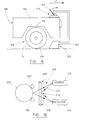
- a laser source and laser detector are provided in a sensing head 100 mounted by means of an arm 102 on the superstructure 104 of an automotive vehicle 106 in a defined relationship to a wheel 108 of the vehicle.
- Detachable mounting means 110 serves to removably secure arm 102 to superstructure 104 under the control of a lever arm 112.
- the mounting means may for example comprise a suction device or a magnetic device or a mechanical clamp device.
- sensing head 100 may be arranged to be merely supported on the ground 114 at approximately the location indicated in Fig 9.
- sensing head 100 is positioned at a location generally radially in-line with the tread 116 of a tyre 118 on wheel 108.
- sensing head 100 is positioned at a location forwardly or rearwardly (with respect to the normal direction F of forward travel of the vehicle), so as to be generally in-line with the tread 116 of tyre 118, while wheel 108 is supported on the ground 114.
- sensing head 100 is initially located with a defined relationship to tyre 118, for example by being adjusted with reference to arm 102 so as to have an exactly horizontal attitude. This may be achieved by means of a simple spirit level device (not shown).
- the laser source of sensing head 100 is adapted to produce laser energy as a line or band or stripe which can extend across at least a major portion of the lateral width 120 of tyre 118. This can be achieved by appropriate chose of laser source and/or by optical means known in the laser source technical field.
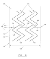
- Fig 8 shows on an enlarged scale, a portion of the tread of tyre 118 including tyre wall portions 122 and patterns 124 of tread grooves 126 provided in the rubber or other polymeric material of the tyre in the usual way.
- the disposition of sensing head 100 and its laser source with respect to tyre 118 is such that the laser line 128 is incident upon the structure of tyre 118 in a non purely-radial direction.
- the laser line is inclined with respect to a radius through the tyre periphery at the location where the laser line intercepts the tyre.
- the laser line 128 intercepts the top surface 130 of the tread along a line 132 having (in Fig 8) three portions 134, 136 and 138.
- the laser line 128 intercepts the bottom surface 140 of the tread patterns 124 at two offset or displaced locations providing the two further portions 142, 144 of the laser line.
- the degree of offset between the portions 134, 136 and 138 as against the portions 142, 144 amounts to a dimension 146, and this offset dimension 146 enables simple calculation of the tread depth on the basis of the angle of incidence of the laser beam with the tyre, which latter is defined by the attitude of the laser emitter in sensing head 100 and the overall attitude of the sensing head with respect to the tyre 118. These quantities are (for a horizontal attitude of the sensing head) known parameters which can be readily determined for a given set of apparatus .
- the laser line image provided by the line portions 134, 136, 138 and the offset line portions 142 and 144 with a degree of offset indicated at 146 provides a measure of the tread depth. Additionally, the profile of the laser line 128 provides an indication of the entire tread/tyre profile at that particular location.
- a laser or other radiation source providing a radiation line extending laterally across a portion of the tyre width enables, by means of the above-discussed line-offset technique, a determination of tread depth and tread profile, on the basis of the angular data relating to the non-radial incidence of the laser or other incident energy.
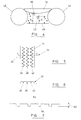
- a vehicle tyre 200 is shown in abutting relationship with positioning rods 202, 204 of tread assessment apparatus 206 otherwise constructed as described above and comprising an external window 208 through which an energy beam 210 passes for tread assessment purposes as described above from source 212 for reflection to detector 214, all as described above.
- reflection occurs from an internal surface 218 of window 208 to detector 214, whereby there is produced a reference or datum line enabling analysis of the positional relationship of tyre 200 with respect to the apparatus 206.
- the datum line serves as a reference whereby the proper attitude of the tyre with respect to the apparatus 206 can be readily achieved or adjusted for by means of the software of the system.
- Figs 11 and 12 show a practical embodiment of the structure described above in relation to Fig 10 and corresponding parts are numbered accordingly.
- the positioning bars or rods 202, 204 are mounted in mounting cups 220 and tyre 200 is moved into abutting engagement with the bars so as to define an exact proximity for the tyre.
- the mounting bars or rods can be journalled in bearings to allow for free rotation when the tyre is rotated between successive analysis routines, or when effecting an overall tyre assessment.
- the apparatus will be - constructed so that once the defined proximity has been established, and likewise the exact alignment of the apparatus, the latter is then fixed in this defined position with respect to the tyre and the bars or rods can then be removed so that the tyre can freely rotate.
- This arrangement is advantageous in terms of avoiding direct contact and the transmission of vibration to the apparatus.
- the method and apparatus is substantially as described above in the preceding embodiments, but the apparatus is repositioned so as to face axially of the tyre, instead of radially, and to be positioned suitably in relation to the sidewall of the tyre instead of in relation to its tread.
- the procedural and analytical steps are substantially the same as described above and the data obtained in the method enables a profile to be obtained of the tyre sidewall whereby discontinuities, notably protuberances, therein can be immediately identified for remedial action or for replacement purposes.
Landscapes
- Physics & Mathematics (AREA)
- General Physics & Mathematics (AREA)
- Length Measuring Devices By Optical Means (AREA)
- Tires In General (AREA)
Applications Claiming Priority (12)
| Application Number | Priority Date | Filing Date | Title |
|---|---|---|---|
| GBGB9614025.6A GB9614025D0 (en) | 1996-07-04 | 1996-07-04 | Tyre tread assessment |
| GB9614025 | 1996-07-04 | ||
| GB9614591 | 1996-07-11 | ||
| GBGB9614591.7A GB9614591D0 (en) | 1996-07-11 | 1996-07-11 | Tyre tread assessment |
| GB9618397 | 1996-09-04 | ||
| GBGB9618397.5A GB9618397D0 (en) | 1996-09-04 | 1996-09-04 | tyre tread assessment |
| GB9624309 | 1996-11-22 | ||
| GBGB9624309.2A GB9624309D0 (en) | 1996-11-22 | 1996-11-22 | Tyre tread assessment |
| GBGB9708779.5A GB9708779D0 (en) | 1996-07-04 | 1997-05-01 | Tyre tread assessment |
| GB9708779 | 1997-05-01 | ||
| GB9709841A GB2314928B (en) | 1996-07-04 | 1997-05-16 | Tyre condition assessment |
| GB9709841 | 1997-05-16 |
Publications (2)
| Publication Number | Publication Date |
|---|---|
| EP0816799A2 true EP0816799A2 (fr) | 1998-01-07 |
| EP0816799A3 EP0816799A3 (fr) | 1998-01-28 |
Family
ID=27547263
Family Applications (1)
| Application Number | Title | Priority Date | Filing Date |
|---|---|---|---|
| EP97304630A Withdrawn EP0816799A3 (fr) | 1996-07-04 | 1997-06-27 | Mesure de la condition d'un pneumatique |
Country Status (7)
| Country | Link |
|---|---|
| US (1) | US6069966A (fr) |
| EP (1) | EP0816799A3 (fr) |
| JP (1) | JP3464678B2 (fr) |
| KR (1) | KR20000023566A (fr) |
| CN (1) | CN1227629A (fr) |
| CA (1) | CA2259664A1 (fr) |
| WO (1) | WO1998001721A1 (fr) |
Cited By (18)
| Publication number | Priority date | Publication date | Assignee | Title |
|---|---|---|---|---|
| WO1998034090A1 (fr) * | 1997-02-03 | 1998-08-06 | Buerger Joachim | Procede et dispositif pour mesurer la profondeur de profil d'un pneu de vehicule |
| US6169290B1 (en) | 1997-08-22 | 2001-01-02 | Valmet-Karlstad Ab | Method and measuring device for measuring at an envelope surface |
| EP1515129A1 (fr) * | 2003-09-04 | 2005-03-16 | Snap-on Equipment Srl a unico socio. | Balayage optique par points de la condition d'un pneu d'une roue de véhicule (avec machine d'équilibrage de roue) |
| WO2005121698A1 (fr) | 2004-06-03 | 2005-12-22 | Snap-On Incorporated | Systeme et procede sans contact d'analyse de pneus |
| DE10032387B4 (de) * | 2000-07-06 | 2006-08-31 | Continental Aktiengesellschaft | Verfahren und Vorrichtung zur Vermessung eines Profils einer Oberfläche |
| DE102006055059A1 (de) * | 2006-11-22 | 2008-07-31 | Kt Projektentwicklungs Gmbh | Vorrichtung zum Messen der Profiltiefe von Kraftfahrzeugreifen |
| CN100462671C (zh) * | 2007-02-05 | 2009-02-18 | 深圳深蓝精机有限公司 | 激光外径检测仪 |
| EP2211161A1 (fr) * | 2009-01-22 | 2010-07-28 | Snap-on Equipment Srl a unico socio | Système de diagnostic de roue |
| WO2010115390A1 (fr) * | 2009-04-08 | 2010-10-14 | Ventech Gmbh | Procédé et dispositif destiné à déterminer la profondeur de sculpture d'un pneumatique de véhicule |
| EP2487477A1 (fr) | 2011-02-10 | 2012-08-15 | Snap-on Equipment Srl a unico socio | Banc d'essai de frein |
| WO2013007479A1 (fr) | 2011-07-11 | 2013-01-17 | Robert Bosch Gmbh | Dispositif et procédé optiques de contrôle de pneumatiques |
| DE102013207374A1 (de) | 2013-04-23 | 2014-10-23 | Robert Bosch Gmbh | Vorrichtung und Verfahren zum Erkennen von Beschriftungen auf Fahrzeugreifen |
| CN105136037A (zh) * | 2015-09-28 | 2015-12-09 | 北京泰诚信测控技术股份有限公司 | 一种被动齿轮端面跳动测量装置 |
| FR3066815A1 (fr) * | 2017-05-23 | 2018-11-30 | IFP Energies Nouvelles | Procede de controle de l'etat d'une surface interne d'un pneumatique |
| DE102019121662A1 (de) * | 2019-08-12 | 2021-02-18 | Carl Zeiss Optotechnik GmbH | Verfahren zur Prüfung eines Reifens |
| DE102020205474A1 (de) | 2020-04-30 | 2021-11-04 | Continental Reifen Deutschland Gmbh | Vorrichtung zum Erfassen eines Profils einer Oberfläche und Verfahren zum Betreiben dieser Vorrichtung |
| DE102020205473A1 (de) | 2020-04-30 | 2021-11-04 | Continental Reifen Deutschland Gmbh | Verfahren zum Erfassen eines Profils einer Oberfläche und Vorrichtung zum Durchführen des Verfahrens |
| DE102023001693A1 (de) | 2023-04-27 | 2024-10-31 | Mercedes-Benz Group AG | Verfahren zur Überprüfung einer sachgemäßen Bereifung eines Fahrzeugs |
Families Citing this family (73)
| Publication number | Priority date | Publication date | Assignee | Title |
|---|---|---|---|---|
| DE19937078C2 (de) * | 1999-08-06 | 2003-08-28 | Continental Teves Ag & Co Ohg | Meßeinrichtung zur berührungslosen Messung von Reifenkräften |
| US6523407B1 (en) * | 1999-08-31 | 2003-02-25 | Torque-Traction Technologies, Inc. | Apparatus and method for balancing a vehicular driveshaft |
| US8266465B2 (en) | 2000-07-26 | 2012-09-11 | Bridgestone Americas Tire Operation, LLC | System for conserving battery life in a battery operated device |
| US7161476B2 (en) | 2000-07-26 | 2007-01-09 | Bridgestone Firestone North American Tire, Llc | Electronic tire management system |
| JP4673479B2 (ja) * | 2000-10-06 | 2011-04-20 | 住友ゴム工業株式会社 | タイヤ動的プロファイル測定方法 |
| IT1314455B1 (it) * | 2000-11-20 | 2002-12-13 | Butler Eng & Marketing | Apparecchiatura per l'identificazione e la manutenzione di pneumaticie ruote con pneumatico |
| WO2002082070A1 (fr) * | 2001-04-04 | 2002-10-17 | Pemstar, Inc. | Systeme de detection de defaut de pneumatique de type dentelure |
| US6907781B2 (en) * | 2002-11-05 | 2005-06-21 | Snap-On Incorporated | Wheel balancing system with integrated wheel lift, loaded mode testing, and wheel imaging system |
| US8284390B1 (en) | 2003-02-20 | 2012-10-09 | Hunter Engineering Company | Vehicle tire changing system with tool positioning sensor |
| US7355687B2 (en) * | 2003-02-20 | 2008-04-08 | Hunter Engineering Company | Method and apparatus for vehicle service system with imaging components |
| ATE303587T1 (de) * | 2003-09-04 | 2005-09-15 | Snap On Equip Srl Unico Socio | Verfahren zur abstimmung eines fahrzeugrades |
| EP1512953B1 (fr) * | 2003-09-04 | 2008-12-10 | Snap-on Equipment Srl a unico socio. | Procédé et dispositif de balayage optique d' une roue de véhicule |
| US7199873B2 (en) * | 2004-01-27 | 2007-04-03 | Snap-On Equipment Srl A Unico Socio | Method and apparatus for balancing a motor vehicle wheel |
| KR100610681B1 (ko) * | 2004-11-30 | 2006-08-09 | 한국타이어 주식회사 | 그린타이어의 런아웃 균일성 측정장치 |
| JP4887373B2 (ja) * | 2005-11-22 | 2012-02-29 | シェーファー・フランク・ハー | タイヤの形状深さおよび形状の種類ならびに走行時の車両の速度および地上高の検出装置 |
| EP1996897B2 (fr) * | 2006-03-23 | 2014-10-22 | Bernward Mähner | Procédé de mesure spatiale d'objets à déplacement rapide |
| EP1845338B1 (fr) * | 2006-04-13 | 2013-07-17 | Snap-on Equipment Srl a unico socio | Procédé de lecture optique de la surface de la chape du pneu d'une roue de véhicule |
| JP2010073216A (ja) * | 2006-05-18 | 2010-04-02 | Nyuurii Kk | ロールスキャナ及び被写体の円周面を読み取る方法 |
| ITMO20060267A1 (it) * | 2006-09-05 | 2008-03-06 | Sicam Srl | Macchina equilibratrice perfezionata per ruote di veicoli |
| US7578180B2 (en) * | 2007-06-29 | 2009-08-25 | The Goodyear Tire & Rubber Company | Tread depth sensing device and method for measuring same |
| JP2009031034A (ja) * | 2007-07-25 | 2009-02-12 | Bridgestone Corp | タイヤのラジアルランナウト測定方法および装置 |
| DE102007054156A1 (de) * | 2007-11-12 | 2009-05-14 | Ventech Gmbh | Verfahren zum Feststellen des Druckes und der Profiltiefe bei einem Fahrzeugreifen |
| EP2141475B1 (fr) * | 2008-07-03 | 2013-03-27 | Snap-on Equipment Srl a unico socio | Appareil pour déterminer l'état d'une chape de pneu d'une roue de véhicule |
| US7805987B1 (en) | 2008-08-19 | 2010-10-05 | Smith Bradley R | System and method for pneumatic tire defect detection |
| CL2009001393A1 (es) * | 2009-06-10 | 2011-07-08 | Marcelo Alberto Olivares Godoy 31 5% | Metodo para inspeccionar neumaticos de grandes dimensiones, que permite detectar in situ la condicion de este, que comprende las etapas de; calibrar un equipo de ultrasonido; determinar el espesor remanente de caucho; ejecutar un barrido ultrasonido sobre el neumatico; y recibir ecos de respuesta para obtener su condicion interna. |
| US8171783B2 (en) * | 2009-11-02 | 2012-05-08 | Tire Measurements, Inc. | Tire tread scanner drive-over unit |
| DE102010003461A1 (de) | 2010-03-30 | 2011-10-06 | Robert Bosch Gmbh | Verfahren zur Bestimmung der Taumelbewegung eines Fahrzeugrades |
| US8824878B2 (en) * | 2010-11-25 | 2014-09-02 | Toyo Tire & Rubber Co., Ltd. | Illumination device and inspection device of tire |
| CA2762175C (fr) * | 2011-01-26 | 2018-07-24 | The Goodyear Tire & Rubber Company | Systeme et methode de suivi d'un procede de rechapage des pneus |
| ITMO20110136A1 (it) * | 2011-05-26 | 2012-11-27 | Sicam Srl | Macchina equilibratrice per l'equilibratura di ruote di veicoli |
| US9805697B1 (en) | 2012-06-01 | 2017-10-31 | Hunter Engineering Company | Method for tire tread depth modeling and image annotation |
| RU2742316C2 (ru) * | 2012-07-31 | 2021-02-04 | Пирелли Тайр С.П.А. | Способ сегментации поверхности шины и устройство, функционирующее согласно этому способу |
| FR2996640B1 (fr) * | 2012-10-09 | 2015-11-13 | Michelin & Cie | Procede pour mesurer l'usure de la bande de roulement d'un pneumatique |
| DE102012224260A1 (de) * | 2012-12-21 | 2014-06-26 | Robert Bosch Gmbh | Vorrichtung und Verfahren zur Messung der Profiltiefe eines Reifens |
| US10507700B2 (en) | 2013-07-31 | 2019-12-17 | Compagnie Generale Des Etablissements Michelin | System and method for analyzing tire tread parameters |
| CN104457608A (zh) * | 2013-09-16 | 2015-03-25 | 上海航天精密机械研究所 | 圆柱体尺寸误差检测系统 |
| DE102014205515A1 (de) * | 2014-03-25 | 2015-10-01 | Robert Bosch Gmbh | Verfahren und Vorrichtung zum Überprüfen der Reifenmontage an einem Fahrzeug |
| DE102014207604A1 (de) * | 2014-04-23 | 2015-10-29 | Robert Bosch Gmbh | Schutzvorrichtung für einen Oberflächenspiegel eines optischen Messsystems |
| GB2531534A (en) * | 2014-10-20 | 2016-04-27 | Pre-Chasm Res Ltd | Vehicle tyre inspection |
| WO2016099655A1 (fr) * | 2014-12-16 | 2016-06-23 | Bridgestone Americas Tire Operations, Llc | Dispositif, système et procédé de mesure optique de profondeur de sculpture |
| US9707806B2 (en) | 2015-02-06 | 2017-07-18 | Love's Travel Stops & Country Stores, Inc. | Vehicle servicing and monitoring method and system |
| JP6591762B2 (ja) | 2015-02-27 | 2019-10-16 | 三菱重工業株式会社 | 摩耗検査装置、摩耗検査方法及びプログラム |
| KR20170038416A (ko) | 2015-09-30 | 2017-04-07 | 금호타이어 주식회사 | 그린타이어 원주 및 진원도 측정 장치 |
| ITUA20162722A1 (it) * | 2016-04-19 | 2017-10-19 | Butler Eng And Marketing S P A | Dispositivo e metodo per l'analisi e il rilevamento di caratteristiche geometriche di un oggetto |
| US20170368890A1 (en) | 2016-06-24 | 2017-12-28 | Ford Global Technologies, Llc | Tire monitor |
| CN107764186A (zh) * | 2016-08-16 | 2018-03-06 | 宁波江丰电子材料股份有限公司 | 滚花的检测方法 |
| DE102017204172A1 (de) * | 2017-03-14 | 2018-09-20 | Continental Reifen Deutschland Gmbh | Crawler |
| US10773557B1 (en) * | 2017-05-18 | 2020-09-15 | State Farm Mutual Automobile Insurance Company | System and method for using image data to determine tire quality |
| DE102017208810A1 (de) | 2017-05-24 | 2018-11-29 | Cst Gmbh | Vorrichtung und Verfahren zur Messung der Profiltiefe eines Reifens |
| DE102017218902B4 (de) * | 2017-10-23 | 2025-04-30 | Volkswagen Aktiengesellschaft | Reifenüberwachungsvorrichtung, Kraftfahrzeug und Verfahren zum Überwachen eines Zustands eines Reifens |
| JP2019086293A (ja) * | 2017-11-01 | 2019-06-06 | 株式会社ブリヂストン | タイヤ溝残量測定装置及びタイヤ溝残量測定システム |
| US11112239B1 (en) | 2017-11-10 | 2021-09-07 | Hunter Engineering Company | Method for tire shoulder tread wear evaluation |
| KR102003288B1 (ko) * | 2017-12-08 | 2019-07-24 | 주식회사 승화기술정책연구소 | 광섬유센서를 이용한 이동식 축중계 및 그 운용 방법 |
| ES2909398T3 (es) * | 2017-12-11 | 2022-05-06 | Butler Eng & Marketing S P A | Unidad para detectar características geométricas de un componente de una rueda con neumático de un vehículo |
| US11453259B2 (en) * | 2018-02-01 | 2022-09-27 | Pixart Imaging Inc. | Object surface managing method and object surface managing system |
| CN108776030A (zh) * | 2018-06-20 | 2018-11-09 | 安徽知之信息科技有限公司 | 一种新能源汽车车胎检测装置 |
| CN108534705B (zh) * | 2018-06-25 | 2020-11-24 | 嘉兴量创科技有限公司 | 一种自动轮胎花纹深度测量检测方法 |
| CN108871225B (zh) * | 2018-06-25 | 2020-11-24 | 嘉兴量创科技有限公司 | 一种胎纹自动检测台 |
| DE102018130800B4 (de) * | 2018-12-04 | 2021-10-14 | Die Radwasch GmbH | Vorrichtung zur Profiltiefenmessung und Wäsche von Kfz-Reifen |
| CN110220473A (zh) * | 2019-06-05 | 2019-09-10 | 陈子昂 | 轮胎花纹沟深度测量方法、装置及设备 |
| CN110220455B (zh) * | 2019-06-06 | 2021-05-07 | 贵州轮胎股份有限公司 | 检测轮胎缠绕工艺参数的装置及方法 |
| CN110751633A (zh) * | 2019-10-11 | 2020-02-04 | 上海眼控科技股份有限公司 | 基于深度学习的多轴大车制动检测方法、装置、系统 |
| CN110849286B (zh) * | 2019-11-27 | 2020-10-02 | 湖南翔龙飞机有限公司 | 一种飞机轮胎出厂检测装置 |
| CN111624006A (zh) * | 2020-07-03 | 2020-09-04 | 河南万国科技股份有限公司 | 一种基于彩色三色互补编码条纹激光投影的轮胎监测装置 |
| CN114076572B (zh) * | 2020-08-13 | 2024-06-21 | 山东新凌志检测技术有限公司 | 一种基于单点激光测量技术的轮胎花纹深度测量系统 |
| JP7648428B2 (ja) * | 2021-04-21 | 2025-03-18 | Toyo Tire株式会社 | タイヤ溝計測装置およびタイヤ溝計測方法 |
| KR102335117B1 (ko) * | 2021-04-21 | 2021-12-07 | 주식회사 아이엑스 | 타이어 마모 측정 및 타이어 상태 진단 장치 |
| DE102021118449B3 (de) | 2021-07-16 | 2022-09-08 | Gid Gmbh | Vorrichtung und Verfahren zur Bildaufnahme eines Reifens eines Fahrzeugs |
| CN118556006B (zh) * | 2022-04-01 | 2026-04-14 | 华为技术有限公司 | 轮胎监测系统 |
| KR20240121997A (ko) | 2023-02-03 | 2024-08-12 | 한국타이어앤테크놀로지 주식회사 | 성형 트랜스퍼 홀더 진원도 교정 가이드 도구 및 이를 이용한 진원도 교정방법 |
| US20240326526A1 (en) * | 2023-03-28 | 2024-10-03 | Snap-On Incorporated | Methods and Systems for Automatic Condition Analysis of Vehicle Tires |
| WO2025024919A1 (fr) * | 2023-07-28 | 2025-02-06 | 3Dm Devices Inc. | Appareil d'analyse de pneu et ses procédés d'utilisation |
| WO2025123140A1 (fr) * | 2023-12-16 | 2025-06-19 | 3Dm Devices Inc. | Procédés et systèmes d'inspection de pneus et de génération de données d'inspection de qualité de pneu |
Family Cites Families (11)
| Publication number | Priority date | Publication date | Assignee | Title |
|---|---|---|---|---|
| DE1809459A1 (de) * | 1968-11-18 | 1970-06-11 | Dr Ekkehard Fuchs | Verfahren und Anordnung zur Messung der Profiltiefe von Kraftfahrzeugreifen und zur Auswertung der Messergebnisse |
| US5054918A (en) * | 1990-02-02 | 1991-10-08 | Fmc Corporation | Light scanning system for measurement of orientation and physical features of a workpiece |
| FR2665255A1 (fr) * | 1990-07-24 | 1992-01-31 | Inrets | Dispositif pour evaluer le degre d'usure des pneumatiques de vehicules. |
| US5249460A (en) * | 1991-12-16 | 1993-10-05 | Bridgestone Corporation | Method and apparatus for measuring irregular tread wear |
| US5245867A (en) * | 1991-12-16 | 1993-09-21 | Bridgestone Corporation | Method and apparatus for measuring tire parameters |
| DE4316984A1 (de) * | 1993-05-21 | 1994-08-18 | Daimler Benz Ag | Verfahren und eine Vorrichtung zur automatischen Ermittlung der Profiltiefe von Fahrzeugreifen |
| GB9418091D0 (en) * | 1994-09-08 | 1994-10-26 | Russell Malcom B | Tyre surface scanner |
| US5561244A (en) * | 1995-03-10 | 1996-10-01 | Bridgestone/Firestone, Inc. | Method and apparatus for measuring the dynamic camber of vehicle tires |
| DE29508978U1 (de) * | 1995-05-31 | 1995-08-10 | Bürger, Joachim, Country Wexford | Meßgerät zur Messung der Profiltiefe von Kraftfahrzeugreifen |
| TW341654B (en) * | 1995-05-26 | 1998-10-01 | Burger Joachim | Tread depth measuring device |
| GB9516968D0 (en) * | 1995-08-18 | 1995-10-18 | Mot Technologies Ltd | Automated system for vehicle condition evaluation |
-
1997
- 1997-06-27 EP EP97304630A patent/EP0816799A3/fr not_active Withdrawn
- 1997-07-03 JP JP50499698A patent/JP3464678B2/ja not_active Expired - Fee Related
- 1997-07-03 US US08/888,213 patent/US6069966A/en not_active Expired - Fee Related
- 1997-07-03 WO PCT/IB1997/001100 patent/WO1998001721A1/fr not_active Ceased
- 1997-07-03 CN CN97197188A patent/CN1227629A/zh active Pending
- 1997-07-03 CA CA002259664A patent/CA2259664A1/fr not_active Abandoned
-
1999
- 1999-01-04 KR KR1019997000010A patent/KR20000023566A/ko not_active Abandoned
Cited By (28)
| Publication number | Priority date | Publication date | Assignee | Title |
|---|---|---|---|---|
| WO1998034090A1 (fr) * | 1997-02-03 | 1998-08-06 | Buerger Joachim | Procede et dispositif pour mesurer la profondeur de profil d'un pneu de vehicule |
| US6169290B1 (en) | 1997-08-22 | 2001-01-02 | Valmet-Karlstad Ab | Method and measuring device for measuring at an envelope surface |
| DE10032387B4 (de) * | 2000-07-06 | 2006-08-31 | Continental Aktiengesellschaft | Verfahren und Vorrichtung zur Vermessung eines Profils einer Oberfläche |
| US7466430B2 (en) | 2003-09-04 | 2008-12-16 | Snap-On Equipment Srl A Unico Socio | Method and apparatus for optically scanning a pneumatic tire of a vehicle wheel |
| EP1515129A1 (fr) * | 2003-09-04 | 2005-03-16 | Snap-on Equipment Srl a unico socio. | Balayage optique par points de la condition d'un pneu d'une roue de véhicule (avec machine d'équilibrage de roue) |
| WO2005121698A1 (fr) | 2004-06-03 | 2005-12-22 | Snap-On Incorporated | Systeme et procede sans contact d'analyse de pneus |
| US7269997B2 (en) | 2004-06-03 | 2007-09-18 | Snap-On Incorporated | Non-contact method and system for tire analysis |
| DE102006055059A1 (de) * | 2006-11-22 | 2008-07-31 | Kt Projektentwicklungs Gmbh | Vorrichtung zum Messen der Profiltiefe von Kraftfahrzeugreifen |
| CN100462671C (zh) * | 2007-02-05 | 2009-02-18 | 深圳深蓝精机有限公司 | 激光外径检测仪 |
| EP2211161A1 (fr) * | 2009-01-22 | 2010-07-28 | Snap-on Equipment Srl a unico socio | Système de diagnostic de roue |
| US8079254B2 (en) | 2009-01-22 | 2011-12-20 | Snap-On Equipment Srl A Unico Socio | Wheel diagnosis system |
| WO2010115390A1 (fr) * | 2009-04-08 | 2010-10-14 | Ventech Gmbh | Procédé et dispositif destiné à déterminer la profondeur de sculpture d'un pneumatique de véhicule |
| US8621919B2 (en) | 2009-04-08 | 2014-01-07 | Ventech Gmbh | Method and apparatus for determining the tread depth of a vehicle tire |
| EP2487477A1 (fr) | 2011-02-10 | 2012-08-15 | Snap-on Equipment Srl a unico socio | Banc d'essai de frein |
| US8857251B2 (en) | 2011-02-10 | 2014-10-14 | Snap-On Equipment Srl A Unico Socio | Brake test stand |
| DE102012202271A1 (de) | 2011-07-11 | 2013-01-17 | Robert Bosch Gmbh | Vorrichtung und Verfahren zur Reifenprüfung |
| WO2013007479A1 (fr) | 2011-07-11 | 2013-01-17 | Robert Bosch Gmbh | Dispositif et procédé optiques de contrôle de pneumatiques |
| US10760898B2 (en) | 2011-07-11 | 2020-09-01 | Beissbarth Gmbh | Optical device and method for inspecting tires |
| DE102013207374A1 (de) | 2013-04-23 | 2014-10-23 | Robert Bosch Gmbh | Vorrichtung und Verfahren zum Erkennen von Beschriftungen auf Fahrzeugreifen |
| WO2014173564A1 (fr) | 2013-04-23 | 2014-10-30 | Robert Bosch Gmbh | Dispositif et procédé d'identification d'inscriptions sur des pneus de véhicules |
| US10313574B2 (en) | 2013-04-23 | 2019-06-04 | Beissbarth Gmbh | Device and method for recognizing inscriptions on vehicle tires |
| CN105136037A (zh) * | 2015-09-28 | 2015-12-09 | 北京泰诚信测控技术股份有限公司 | 一种被动齿轮端面跳动测量装置 |
| CN105136037B (zh) * | 2015-09-28 | 2018-03-27 | 北京泰诚信测控技术股份有限公司 | 一种被动齿轮端面跳动测量装置 |
| FR3066815A1 (fr) * | 2017-05-23 | 2018-11-30 | IFP Energies Nouvelles | Procede de controle de l'etat d'une surface interne d'un pneumatique |
| DE102019121662A1 (de) * | 2019-08-12 | 2021-02-18 | Carl Zeiss Optotechnik GmbH | Verfahren zur Prüfung eines Reifens |
| DE102020205474A1 (de) | 2020-04-30 | 2021-11-04 | Continental Reifen Deutschland Gmbh | Vorrichtung zum Erfassen eines Profils einer Oberfläche und Verfahren zum Betreiben dieser Vorrichtung |
| DE102020205473A1 (de) | 2020-04-30 | 2021-11-04 | Continental Reifen Deutschland Gmbh | Verfahren zum Erfassen eines Profils einer Oberfläche und Vorrichtung zum Durchführen des Verfahrens |
| DE102023001693A1 (de) | 2023-04-27 | 2024-10-31 | Mercedes-Benz Group AG | Verfahren zur Überprüfung einer sachgemäßen Bereifung eines Fahrzeugs |
Also Published As
| Publication number | Publication date |
|---|---|
| CN1227629A (zh) | 1999-09-01 |
| JP3464678B2 (ja) | 2003-11-10 |
| JP2000514555A (ja) | 2000-10-31 |
| CA2259664A1 (fr) | 1998-01-15 |
| EP0816799A3 (fr) | 1998-01-28 |
| US6069966A (en) | 2000-05-30 |
| KR20000023566A (ko) | 2000-04-25 |
| WO1998001721A1 (fr) | 1998-01-15 |
Similar Documents
| Publication | Publication Date | Title |
|---|---|---|
| US6069966A (en) | Apparatus and method for tire condition assessment | |
| KR101104973B1 (ko) | 차량 휠의 공기압 타이어를 광학적으로 스캔하기 위한방법 및 장치 | |
| US8621919B2 (en) | Method and apparatus for determining the tread depth of a vehicle tire | |
| CA2753464C (fr) | Mesure d'un pneu d'un vehicule | |
| US6397164B1 (en) | Device for determining the wheel and/or axle geometry of motor vehicles | |
| WO1998001721B1 (fr) | Appareil et procede d'evaluation de l'etat d'un pneu | |
| CN101479568B (zh) | 用于确定物体定向,例如车轮对准的装置及方法 | |
| CN101358839B (zh) | 确定车轮几何尺寸的方法和设备 | |
| CN101311669B (zh) | 安装或拆卸汽车轮胎的方法和设备 | |
| US5532816A (en) | Laser tracking wheel alignment measurement apparatus and method | |
| US5818574A (en) | Method and apparatus for vehicle wheel alignment testing | |
| US5583797A (en) | Method and apparatus for wheel alignment audit | |
| WO1996010727A1 (fr) | Appareil et procede de scannage de pneumatiques | |
| KR101105096B1 (ko) | 차량 휠을 광학적으로 스캔하기 위한 방법 및 장치 | |
| GB2241061A (en) | Light scanning system | |
| HU220577B1 (hu) | Berendezés és eljárás sínhez kötött járművek kerekei gördülési paramétereinek mérésére | |
| EP0565320A2 (fr) | Procédé et dispositif de mesure des paramètres d'une roue dans une machine d'équilibrage de roues | |
| WO1997007380A2 (fr) | Systeme automatique d'evaluation de l'etat d'un vehicule | |
| US5078490A (en) | System and method for checking the aim of a vehicle headlamp | |
| EP2110656A1 (fr) | Appareil pour déterminer l'état d'un ensemble de roue | |
| GB2314928A (en) | Tyre profiling arrangement | |
| CA2201739A1 (fr) | Appareil et procede de scannage de pneumatiques | |
| CN114562952A (zh) | 轮胎花纹深度测量方法、全周花纹深度测量方法及系统 |
Legal Events
| Date | Code | Title | Description |
|---|---|---|---|
| PUAI | Public reference made under article 153(3) epc to a published international application that has entered the european phase |
Free format text: ORIGINAL CODE: 0009012 |
|
| PUAL | Search report despatched |
Free format text: ORIGINAL CODE: 0009013 |
|
| AK | Designated contracting states |
Kind code of ref document: A2 Designated state(s): DE GB IE IT SE |
|
| AK | Designated contracting states |
Kind code of ref document: A3 Designated state(s): AT BE CH DE DK ES FI FR GB GR IE IT LI LU MC NL PT SE |
|
| 17P | Request for examination filed |
Effective date: 19980724 |
|
| RBV | Designated contracting states (corrected) |
Designated state(s): DE GB IE IT SE |
|
| RAP1 | Party data changed (applicant data changed or rights of an application transferred) |
Owner name: SNAP-ON EQUIPMENT LIMITED |
|
| RAP3 | Party data changed (applicant data changed or rights of an application transferred) |
Owner name: SNAP-ON EQUIPMENT LIMITED |
|
| 17Q | First examination report despatched |
Effective date: 20011207 |
|
| STAA | Information on the status of an ep patent application or granted ep patent |
Free format text: STATUS: THE APPLICATION IS DEEMED TO BE WITHDRAWN |
|
| 18D | Application deemed to be withdrawn |
Effective date: 20021108 |