EP0817111A2 - Méthode et appareil de formation d'images - Google Patents
Méthode et appareil de formation d'images Download PDFInfo
- Publication number
- EP0817111A2 EP0817111A2 EP97111335A EP97111335A EP0817111A2 EP 0817111 A2 EP0817111 A2 EP 0817111A2 EP 97111335 A EP97111335 A EP 97111335A EP 97111335 A EP97111335 A EP 97111335A EP 0817111 A2 EP0817111 A2 EP 0817111A2
- Authority
- EP
- European Patent Office
- Prior art keywords
- data
- compression
- raster
- image forming
- coded
- Prior art date
- Legal status (The legal status is an assumption and is not a legal conclusion. Google has not performed a legal analysis and makes no representation as to the accuracy of the status listed.)
- Granted
Links
Images


Classifications
-
- G—PHYSICS
- G06—COMPUTING OR CALCULATING; COUNTING
- G06K—GRAPHICAL DATA READING; PRESENTATION OF DATA; RECORD CARRIERS; HANDLING RECORD CARRIERS
- G06K15/00—Arrangements for producing a permanent visual presentation of the output data, e.g. computer output printers
-
- G—PHYSICS
- G06—COMPUTING OR CALCULATING; COUNTING
- G06T—IMAGE DATA PROCESSING OR GENERATION, IN GENERAL
- G06T9/00—Image coding
- G06T9/004—Predictors, e.g. intraframe, interframe coding
-
- G—PHYSICS
- G06—COMPUTING OR CALCULATING; COUNTING
- G06K—GRAPHICAL DATA READING; PRESENTATION OF DATA; RECORD CARRIERS; HANDLING RECORD CARRIERS
- G06K2215/00—Arrangements for producing a permanent visual presentation of the output data
- G06K2215/0002—Handling the output data
-
- G—PHYSICS
- G06—COMPUTING OR CALCULATING; COUNTING
- G06K—GRAPHICAL DATA READING; PRESENTATION OF DATA; RECORD CARRIERS; HANDLING RECORD CARRIERS
- G06K2215/00—Arrangements for producing a permanent visual presentation of the output data
- G06K2215/0002—Handling the output data
- G06K2215/0005—Accepting output data; Preparing data for the controlling system
- G06K2215/0014—Transforming the printer input data into internal codes
Definitions
- This invention relates to an image forming method and apparatus for forming an image on a print medium.
- an image forming apparatus such as a laser-beam printer, performs image formation while holding raster data for one page in a raster memory.
- Japanese Patent Application Laid-Open No. 6-87521 discloses temporarily translating image data in page description language into coded raster representation as intermediate data, and storing the data represented in coded raster representation.
- objects which were described in the page description language are objects such as "bitmap”, “run-length”, “trapezoid”, “box” and "fast boundary encoding bitmap” in a format which can be subjected to high-speed conversion to raster data, with data amounts less than the amounts of raster data.
- the data translated into the coded raster representation is referred to "coded raster data".
- the coded raster data is transferred to a printing unit (printer engine), while being converted into raster data where dots are arranged in the order of raster scanning.
- the memory resource is saved by holding image data to be printed as coded raster data.
- this status is called "over-run"
- coded raster data cannot be stored in a predetermined memory.
- memory retirement for these cases are predicted. If this technique is used, the resolution of an image as the object of printing and/or the tone-level representation is degraded, thus the necessary memory capacity and processing time are reduced.
- Japanese Patent Application Laid-Open Nos. 4-323060, 6-233141 and 6-284297 propose to compress raster data for reducing memory capacity.
- Japanese Patent Application Laid-Open NO. 6-233141 discloses temporarily converting data in page description language into intermediate data and storing the intermediate data. In a case where the memory capacity for storing the intermediate data is short, or processing for generating the raster data from intermediate data is complicated and it takes too much time, the raster data is generated and compressed prior to printing.
- the former processing must perform the garbage collection for each data compression, which causes overhead in processing time for memory rearrangement, thus degrading the overall performance.
- the latter processing causes memory overhead for link structure or for writing/reading data.
- the present invention has been made in consideration of the above conventional techniques, and has its object to provide an image forming method and apparatus which reliably performs image formation without causing over-run.
- the image forming method and apparatus of the embodiments temporarily converts input page description language data into coded raster data in band units, and performs transmission, while generating raster data from the coded raster data, to a printer engine.
- the image forming method and apparatus reduces the memory capacity by generating raster data from coded raster data by band, and compressing and storing the raster data, in any of the following cases:
- the current compression method is changed to another compression method requiring less memory, otherwise, the resolution and/or tone-level representation is degraded to reduce data amount. Then, compression is performed.
- the image forming method and apparatus performs compression processing while updating a probability prediction table used for arithmetic compression.
- the compressed data size is predicted while updating the probability prediction table, and the data of the updated probability prediction table is stored. Then, upon actual compression, the stored data of the probability prediction table is used as the initial data of the probability prediction table.
- the image forming method and apparatus predicts an expansion processing speed at the same time of prediction of compressed data size, and determines whether or not the expansion processing speed is sufficient to follow data transmission to the printer engine. if the predicted expansion processing speed is not sufficient to follow data transmission, the current compression is changed to another compression method, otherwise, the resolution and/or tone-level representation is degraded to reduce data amount. Then, compression is performed.
- Fig. 1 is a cross-sectional view showing the mechanical structure of a laser-beam printer (hereinafter abbreviated to "LBP") applied to the present embodiment.
- LBP laser-beam printer
- typical format of character pattern (form data) can be registered from a data source (not shown).
- an LBP main body 1000 inputs character information (character coded) and form information supplied from the host computer (11 in Fig. 2) connected as an external device, or macro-instruction and the like, and stores the input data. Further, the LBP main body 1000 generates a character pattern or a form pattern in accordance with the input information, and forms an image on a print sheet as a print medium.
- An operation panel 1012 has operation switches, an LED display and the like.
- a printer control unit 1001 controls the overall LBP 1000, and analyzes character information and the like supplied from the host computer.
- the control unit 1001 mainly converts character information into a video signal of a corresponding character pattern, and outputs the video signal to a laser driver 1002.
- the laser driver 1002 is a circuit for driving a semiconductor laser 1003.
- the laser driver 1002 turns on/off a laser beam 1004 emitted from the semiconductor laser 1003 in accordance with the input video signal.
- the laser beam 1004 is scanned in left and right directions by a rotating polygon mirror 1005, scanning on an electrostatic drum 1006. This forms an electrostatic latent image of the character pattern on the electrostatic drum 1006.
- a latent image is developed by a developing unit 1007 around the electrostatic drum 1006, then transferred to a print sheet.
- a print sheet is a cut sheet contained in a paper cassette 1008 attached to the LBP 1000.
- the print sheet is fed into the apparatus by a paper-feed roller 1009 and conveyance rollers 1010 and 1011, and supplied to the electrostatic drum 1006.
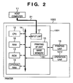
- Fig. 2 is a block diagram showing the construction of a control system of the printing system of the present embodiment.
- the control system mainly comprises the printer control unit 1001 and the host computer 11 connected to the printer control unit 1001 via a predetermined interface using an interface cable 21.
- the printer control unit 1001 comprises a printer CPU 12, an RAM 18, a ROM 13, a system bus 14, an input unit 17, a printing interface (I/F) unit 15 and the like.
- the system bus 14 is connected to an operation unit 1012.
- the printing I/F unit 15 is connected to a printing unit 16.
- the input unit 17 is connected via the interface cable 21 to the host computer 11.
- the host computer 11 sends data of a figure, a character, a bitmap image and the like, in command-format page description language, to the printer control unit 1001.
- the printer CPU 12 controls the respective devices connected to the system bus 14, based on control programs stored in the ROM 13. Further, the printer CPU 12 controls output of image information to the printing unit 16 via the printing I/F unit 15. Further, the printer CPU 12 performs communication processing with the host computer 11 via the input unit 17.
- the printing I/F unit 15 has two band memories 151 respectively for mapping image data to be print-outputted from the printing unit 16. Upon printing, the printer CPU 12 generates raster data in one band memory, while outputs raster data from the other band memory. For printing for one page, the raster-data generation control and raster-data output control are alternately performed by using the two band memories.
- the printing unit 16 prints an image based on the image information inputted via the printing I/F unit 15.
- the ROM 13 holds programs for the controls of the printer CPU 12, including a program for compressing/expanding raster data, and a preparatory compression program for predicting a compressed data size.
- the RAM 18 functions as a main memory or a work memory for the printer CPU 12.
- the RAM 18 is used as a buffering area, an area for mapping image data, a storage area for storing environmental data and the like. Further, the RAM 18 is constructed so as to expand its memory capacity by an optional RAM 19 connected to an expansion port.
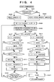
- step S301 the controller 1001 of the printer 1000 receives image data generated in page description language from the host computer 11 via the input unit 17.
- the input page description language is converted into coded raster data in band units.
- the coded raster data in band units will be particularly referred to as "coded band data”.
- the coded band data includes codedd image objects such as band-based divided “bitmap”, “run-length”, “trapezoid”, “box” and “fast boundary encoding bitmap", and a background pattern.
- the resource necessary for mapping the coded band data into full-raster image data i.e., processing time and memory capacity necessary for storing the coded band data for one page, are predicted. That is, by each coded band data included in one page,
- a necessary memory capacity can be obtained from the size of the area in which the coded band data is stored.
- the memory capacity a determination is not only made as to whether or not the memory capacity for generating raster data from the coded band data is sufficient. For example, regarding one band, if predicted processing time necessary for generating raster image data from coded band data exceeds a predetermined period, the raster data of the band is held as compressed raster data. In this case, a work area for compressing the raster data as well as the work area for generating the raster data is required. The determination is made on memory requirement, including such work area.
- processing at step S304 may be performed after one coded band data has been generated, or after coded band data of all the bands included in one page has been generated. Upon determining whether or not the memory resource is insufficient, it is preferable to perform the processing at step S304 periodically, e.g., upon each generation of new coded band data from input data.
- step S304 if it is determined that the resource necessary for generating bitmap data of the current band is sufficient, the process proceeds to step S313. At step S313, it is determined whether or not processing of the current page has been completed. If coded band data still remains, process returns to step S301, and the processing is performed on the remaining data in page description language.
- step S304 determines whether the printer resource is insufficient, i.e., the available memory capacity is insufficient or too much time is necessary for generating raster data. If it is determined at step S304 that the printer resource is insufficient, i.e., the available memory capacity is insufficient or too much time is necessary for generating raster data, the process proceeds to step S305.
- the coded band data is converted into compressed raster data.
- the procedure of conversion will be described.
- raster data is generated from the coded band data and mapped in one of two pre-allocated band memory areas.
- step S306 the compressed data size of the raster data is determined by preparatory compression processing, and probability prediction table data for actual compression is obtained.
- processing time for expansion is predicted from the compressed data size predicted at step S306.
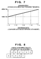
- the prediction of expansion time depends on the compression method. Generally, expansion time is in strong correlation with a compression ratio. In an arithmetic compression method using prediction from peripheral pixels around a pixel of interest, used in the present embodiment, it is experimentally determined that the compression ratio and the expansion processing speed are in correlation as shown in Fig. 7. Accordingly, processing time for expansion can be substantially predicted by using the compressed data size predicted at step S306.
- step S308 the compressed data size predicted at step S306 is compared with the currently-available memory capacity. If it is determined that the memory capacity is sufficient, the process proceeds to step S312, where the band raster data mapped in the band memory is compressed and stored in the memory, and the process returns to step S313.
- step S308 If it is determined at step S308 that the memory capacity is insufficient, the process proceeds to step S309, at which memory area containing coded band data that has been already used for generating raster data, and memory area containing compressed raster data that has become unnecessary are released, thus garbage collection on the entire memory is performed, to obtain a continuity of available memory areas by memory rearrangement.
- step S310 the available memory capacity after the memory rearrangement is compared with the compressed data size predicted at step S306. If it is determined that the memory capacity is sufficient, the process proceeds to step S312. If it is determined that the memory capacity is still insufficient, the process proceeds to step S311, to change the compressing means.
- the compression method of the compressing means is changed to a method which reduces the data amount of raster data while appropriately thinning the data, and again compresses the raster data by the same compression method, and upon expansion, interpolates the thinned data with peripheral pixels.
- This method is an irreversible compression method which causes image degradation.
- step S313 determines whether the mapping of the current page has been completed. If it is determined at step S313 that the mapping of the current page has been completed, the process proceeds to step S314, at which printing of the page is started.
- raster data is generated from the coded band data obtained at step S302, by each band, otherwise, the compressed raster data compressed at step S312 is expanded, and mapped alternately in the two band memories 151. At this time, it is assured that the time for mapping the raster data in the band memory is shorter than time for transmitting the band raster data to the printing unit 16, therefore, over-run never occurs.
- the raster data is transferred by the printing I/F unit 15 to the printing unit 16.
- Steps S314 and S315 are executed in parallel in the two band memories, and in one band memory, sequentially executed. That is, when one band raster image has been transferred from one band memory by the printing I/F unit 15, the subsequent band raster image is mapped in the other band memory. The data generation and data output are alternately performed in the two band memories.
- step S316 for processing of the next page.
- An image for one page is outputted by the above procedure.
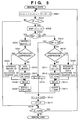
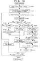
- step S401 When preparatory or actual compression has been started, it is determined at step S401 whether preparatory compression or actual compression is currently performed. If it is determined that preparatory compression is currently performed, the process proceeds to step S403, at which all the values of columns ST[] and MPS[] of a prediction table for compression are initialized with a predetermined initial value "0".
- step S402 at which all the values of prediction table columns ST'[] and MPS'[], obtained by preparatory compression and stored in the RAM 18, are read and stored in the prediction table columns ST[] and MPS[].
- the meanings of these register variables are:
- step S405 the value of a pixel of interest "?" to be encodedd is entered in a register PIX, and its peripheral reference pixels "X" are entered in a register CX.
- ten pixels are employed as the peripheral reference pixels.
- the number of pixels is not limited to ten, and further, reference pixel positions are arbitrarily set. In this case, however, as the number of pixels increases, the size of prediction table increases, and if the number of pixels is too small, the compression ratio is degraded. Further, the compression ratio degrades unless the reference pixel positions are determined in consideration of the characteristic of image data to be compressed.
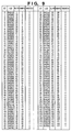
- step S406 a predicted pixel value MPS[CX] corresponding to the reference pixel stored in the register CX is compared with the value of the pixel of interest PIX to determine whether or not they correspond with each other. If these values correspond with each other, the process proceeds to step S414, at which a subinterval value (LSZ[ST[CX]]) of current inferior probability is obtained from the table in Fig. 9, then subtracted from a current interval value A, thus a subintervale value of superior probability is obtained.
- LSZ[ST[CX]] subinterval value of current inferior probability
- step S415 if the superior-probability subinterval value is less than 50% (0x8000), the process proceeds to step S416. If the superior-probability subinterval value is equal to or greater than the inferior-probability subinterval value, the process proceeds to step S417, at which the inferior-probability subintervale value is added to the coded strings, and the interval value is updated with this inferior-probability subinterval value.
- the column ST contains reference numbers of pixel pattens; LSZ, probability values of the pixel patterns.
- the table as shown in Fig. 9 is prepared in advance.
- step S418 the process proceeds to step S418, at which the prediction probability corresponding to the reference pixel value CX is updated to a value of the superior probability table from the table in Fig. 9.
- step S419 coded-output processing (RENORM to be described later) from the coded strings is performed, then process proceeds to step S420.
- step S406 if it is determined at step S406 that the predicted pixel value MPS[CX] corresponding to the reference pixel value CX does not correspond to the value of the pixel of interest PIX, the process proceeds to step S407, at which the current inferior-probability subinterval value (LSZ[ST[CX]]) is obtained from the table in Fig. 9. Then, the obtained value is subtracted from the current interval value A, thus a superior-probability subinterval value is obtained.
- the current inferior-probability subinterval value LSZ[ST[CX]]
- step S408 if this supeior-probability subinterval value is greater than the inferior-probability subinterval value, the process proceeds to step S409, at which the inferior-probability subinterval is added to the coded array, and the interval value is updated with this inferior-probability subinterval value.
- step S410 it is determined whether or not a superior pixel/inferior pixel inverse switch (SWITCH[ST[CX]]) of the current probability table is ON (1). If it is ON (1), the process proceeds to step S411, at which the value of the predicted pixel value MPS[CX] is inversed.
- SWITCH[ST[CX]] superior pixel/inferior pixel inverse switch
- step S412 the prediction probability table column ST[CX] corresponding to the reference pixel CX is updated to a value of the inferior probability table from the table in Fig. 9.
- step S413 coded-output processing (RENORM_E to be described later) from the coded strings is performed, and the process proceeds to step S420.
- step S420 it is determined whether or not compression of the entire image data has been completed. If NO, the process returns to step S405, at which compression is continued with the next pixel as a new pixel of interest.
- step S420 determines whether all the compression of the entire image data has been completed. If it is determined at step S420 that all the compression of the entire image data has been completed, the process proceeds to step S421, at which termination processing of compression (FLUSH to be described later) is executed, thus the compression ends.
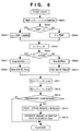
- step S501 the interval register A and the coded register C are shifted by one bit.
- the number of shifts is counted by the counter CT.
- step S502 the counter CT is checked. If the value of the counter CT is "0”, the process proceeds to step S503 and the subsequent steps, and compressed data for one byte is read from the coded register C. On the other hand, if the value of the counter CT is not "0”, the process proceeds to step S518, at which if the value of the interval register A is not less than "0x8000", the RENORM_E processing is terminated, while if the interval register A is less than "0x8000", the process returns to step S501.
- step S503 first, the head one byte of the value of the coded register C, to be outputted to a variable TEMP, and a carry display bit are stored.
- step S504 if the variable TEMP is greater than "0xff", i.e., it has a carry, the process proceeds to step S505.
- step S505 the carry is added to a variable BUFFER holding the latest temporary output, which is not equal to "0xff".
- step S521 If it is determined at step S521 that the current compression is not preparatory compression, the value is outputted (written) at step S506.
- the output is not made by actually writing the value in the memory, but only by incrementing the data counter.
- the increment of the data counter data for one byte is written in the actual memory, and an output-data pointer is updated.
- step S507 if the byte in the BUFFER has been temporarily outputted, all the bytes that were converted by the carry and resulted in "0x00" are outputted, the number of bytes is equal to the value of the counter SC that counted the number of "0x00" bytes since the value of the variable BUFFER was temporarily outputted.
- step S508 the counter SC is cleared.
- step S509 the value from which the carry has been subtracted from the variable TEMP is set in the BUFFER as a new temporary output byte. If it is determined at step S521 that the current compression is preparatory compression, the amount of data to be written into a predetermined counter Camt is integrated at step S522.
- step S510 it is checked whether or not the output byte TEMP is "0xff". If it is determined that the output byte TEMP is "0xff", the process proceeds to step S515, at which the counter SC is simply incremented so as to delay output until the carry is resolved. On the other hand, if it is determined at step S510 that the output byte TEMP is not "0xff", and if it is determined at step S519 that the current compression is not the preparatory compression, the process proceeds to step S511, at which the value of the variable BUFFER, holding the latest temporary output that is not equal to "0xff", is outputted (written).
- step S512 all the bytes that were converted by the carry and resulted in "0x00" are outputted, the number of bytes is equal to the value of the counter SC that counted the number of "0x00" bytes since the value of the variable BUFFER was temporarily outputted.
- variable TEMP is set to the variable BUFFER as a new temporary output byte.
- step S519 If it is determined at step S519 that the current compression is the preparatory compression, the amount of data to be written into the predetermined counter Camt is integrated. This counter is the same as that used at step S522. The value of the counter Camt becomes a predicted compressed data amount.
- step S566 codeds for one byte are removed from the value of the coded register C.
- step S517 the value of the bit-number counter CT is initialized to "8", then, the process proceeds to step S518.
- step S5108 it is checked whether or not the interval register A is less than "0x8000". If YES, the process returns to step S501 to repeat the processing, while if NO, terminates the RENORM_E processing.
- step S601 the value of the interval register A and the value of the coded register C are added, then "1" is subtracted from the value result from the addition, and sixteen significant bits are masked. The resulting value is set to the variable TEMP.
- step S602 the variable TEMP is compared with the value of the coded register C. If the variable TEMP is less than the value of the coded register C, the process proceeds to step S603, at which the coded register C is set to "TEMP+0x8000". If the variable TEMP is not less than the value of the coded register C, the process proceeds to step S604, at which the coded register C is set to the variable TEMP.
- the coded register C has been set to a value with the possible maximum number of zero bits in [C, C + A - 1 ].
- step S605 the coded register C is shifted by the value of the bit counter CT.
- step S606 it is determined whether or not the coded register value has a carry. If YES, the process proceeds to step S607, while if NO, proceeds to step S609.
- step S607 the value obtained by adding the carry to the variable BUFFER is outputted (written).
- step S608 all the bytes that were converted by the carry and resulted in "0x00" are outputte, the number of bytes is equal to the value of the counter SC that counted the number of "0xff" bytes since the value of the variable BUFFER was temporarily outputted.
- step S606 determines whether the coded register value has no carry. If it is determined at step S606 that the coded register value has no carry, the process proceeds to step S609, at which the variable BUFFER is outputted (written).
- step S610 all the bytes from the BUFFER are outputted as "0xff".
- the number of bytes is equal to the value of the counter SC that has counted the number of "0xff" bytes since the value of the variable BUFFER was temporarily outputted.
- step S613 it is determined whether or not the current compression is preparatory compression. If YES, the process proceeds to step S614, at which all the values of the final prediction table columns ST[] and MPS[], sequentially updated by the preparatory compression, are stored in the prediction table columns ST'[] and MPS'[] which are storage areas in the RAM 18. The stored values are read and used upon actual compression and expansion.
- step S314 (Fig. 3) will be described with reference to the flowcharts of Figs. 10 and 11.
- step S1001 the prediction table columns ST'[] and MPS'[], generated in the above preparatory compression and stored, are read into the prediction table columns ST[] and MPS[].
- step S1002 the coded register C is cleared to "0", then the data is obtained for one byte by input-data obtaining processing (BYTEIN) to be described later, and the register is shifted by eight bits. Thus, data for three bytes are obtained, and the interval register A is initialized to "0x10000".
- step S1003 the peripheral reference pixel "X" of the pixel of interest "?" as shown in Fig. 8 is entered in the register CX. Note that the peripheral reference pixel must be the same as that upon compression.
- CHIGH S1005 in Fig. 10 denotes the value of the sixteen significant bits of the coded register C.
- Fig. 11 shows the flowchart of coded-input processing (RENORM_D) at step S1017, and Fig. 12, the flowchart of input-data obtaining processing (BYTEIN) called at step S1002 in Fig. 10 and S1102 in Fig. 11.
- the printer according to the present embodiment data which seems to cause over-run due to too much time for mapping raster data from coded band data, or data requiring too large memory capacity, are converted into raster data and compressed in advance. This prevents over-run or status where the data cannot be stored into a memory. Further, the present embodiment employs, as a method for compressing raster data, a method which easily predicts expansion time from the result of compression. This more exactly predicts occurrence of over-run or memory shortage. Accordingly, regarding data that requires no mapping into raster data and compression, such processings are avoided, thus overhead of processing for prevention of over-run can be minimized.
- the present embodiment employes the compression procedure based on the JBIG method, therefore, prediction tables LST and MPS, more suitable to data to be compressed, can be generated by preparatory compression. Accordingly, the preparatory compression can improve the compression ratio as well as prediction of compressed data size.
- the compression is made by utilizing a part of sequential mode in so-called JBIG compression.
- the compression mode may be a progressive mode, otherwise, an arbitrary optional function such as ATMOVE may be added. Further, any other arithmetic coding compression method may be employed.
- the compression method is not limited to arithmetic coding compression, but an arbitrary compression method can be adopted from various methods such as a packbits compression, LZ77 and LZ78 compressions, a Huffman compression, an MR compression, an MH compression, an MMR compression, FBE compression and a JPEG compression.
- the present embodiment employs a lossy compression that reduces data amount by thinning pixels and retries compression, then interpolates the compressed data upon expansion.
- a compression method having a relatively-low compression ratio such as a packbits compression is switched to a compression method having a relatively-high compression ratio such as a JBIG or LZ77 compression; otherwise, a lossless compression with a low compression ratio such as a Huffman compression is switched to a lossy compression with a high compression ratio such as a JPEG compression.
- the same JPEG compression is used, and its compression ratio is changed to a higher compression ratio (low quality) by parameters.
- the processing speed upon expansion is predicted by experimentally using the compression ratio (ratio between data size before compression and compressed data size), however, the prediction method differs in use of compression method(s) other than that of the present embodiment.
- the expansion time may be predicted by experimentally using the correlation as in the above embodiment.
- preparatory expansion may also be performed to obtain expansion time. In this case, it provides a demerit of increase in processing time for preparatory compression, however, it provides a merit of more exact prediction of expansion time.
- the present invention can be applied to a system constituted by a plurality of devices or to an apparatus comprising a single device.
- the invention is also applicable to a case where the invention is embodied by supplying a program to a system or apparatus.
- a storage medium storing a program according to the invention, constitutes the invention.
- the system or apparatus installed with the program read from the medium realizes the functions according to the invention.
- the present invention can be applied to a system constituted by a plurality of devices (e.g., host computer, interface, reader, printer) or to an apparatus comprising a single device (e.g., copy machine, facsimile).
- devices e.g., host computer, interface, reader, printer
- apparatus comprising a single device (e.g., copy machine, facsimile).
- the object of the present invention can be also achieved by providing a storage medium storing program codeds for performing the aforesaid processes to a system or an apparatus, reading the program codeds with a computer (e.g., CPU, MPU) of the system or apparatus from the storage medium, then executing the program.
- a computer e.g., CPU, MPU
- the program codeds read from the storage medium realize the functions according to the embodiments, and the storage medium storing the program codeds constitutes the invention.
- the storage medium such as a floppy disk, a hard disk, an optical disk, a magneto-optical disk, CD-ROM, CD-R, a magnetic tape, a non-volatile type memory card, and ROM can be used for providing the program codeds.
- the present invention includes a case where an OS (operating system) or the like working on the computer performs a part or entire processes in accordance with designations of the program codeds and realizes functions according to the above embodiments.
- the present invention also includes a case where, after the program codeds read from the storage medium are written in a function expansion card which is inserted into the computer or in a memory provided in a function expansion unit which is connected to the computer, CPU or the like contained in the function expansion card or unit performs a part or entire process in accordance with designations of the program codeds and realizes functions of the above embodiments.
- the storage medium stores program codeds corresponding to the flowcharts described in the embodiments.
- the compressed data size is predicted by preparatory compression, which minimizes the number of times of garbage correction, and prevents degradation of the overall performance due to processing time overhead caused by memory rearrangement.
- the compression ratio of actual compression can be improved by reusing a prediction probability table generated upon preparatory compression.
- a printer converts print data in page description language into coded band data as a set of objects such as run-length data, trapezoid data and the like, in band units. Processing time to generate raster data from the coded band data is predicted, and the predicted time is used for determining whether or not the raster-data generation takes time longer than time for transmitting data to a printer engine. If it is determined that the raster-data generation time is longer than the data transmission time, raster data is generated from coded band data, and compressed and stored as preparation for printing. At this time, preparatory compression is performed to predict time for expanding the compressed data, for determining whether or not time for expansion is longer than data transmission time. If the expansion time is longer than the data trasnmission time, a coding method is changed, and the preparatory compression is performed again. If the expansion time is not longer than the data transmission time, the data is compressed and stored.
Landscapes
- Engineering & Computer Science (AREA)
- Physics & Mathematics (AREA)
- General Physics & Mathematics (AREA)
- Theoretical Computer Science (AREA)
- General Engineering & Computer Science (AREA)
- Multimedia (AREA)
- Record Information Processing For Printing (AREA)
- Compression Of Band Width Or Redundancy In Fax (AREA)
- Compression, Expansion, Code Conversion, And Decoders (AREA)
- Editing Of Facsimile Originals (AREA)
- Memory System (AREA)
- Storing Facsimile Image Data (AREA)
Applications Claiming Priority (3)
| Application Number | Priority Date | Filing Date | Title |
|---|---|---|---|
| JP176682/96 | 1996-07-05 | ||
| JP17668296 | 1996-07-05 | ||
| JP8176682A JPH1023271A (ja) | 1996-07-05 | 1996-07-05 | 画像形成方法とその装置 |
Publications (3)
| Publication Number | Publication Date |
|---|---|
| EP0817111A2 true EP0817111A2 (fr) | 1998-01-07 |
| EP0817111A3 EP0817111A3 (fr) | 2002-10-09 |
| EP0817111B1 EP0817111B1 (fr) | 2006-08-02 |
Family
ID=16017888
Family Applications (1)
| Application Number | Title | Priority Date | Filing Date |
|---|---|---|---|
| EP97111335A Expired - Lifetime EP0817111B1 (fr) | 1996-07-05 | 1997-07-04 | Méthode et appareil de formation d'images |
Country Status (4)
| Country | Link |
|---|---|
| US (1) | US6181435B1 (fr) |
| EP (1) | EP0817111B1 (fr) |
| JP (1) | JPH1023271A (fr) |
| DE (1) | DE69736412D1 (fr) |
Cited By (2)
| Publication number | Priority date | Publication date | Assignee | Title |
|---|---|---|---|---|
| US7463372B2 (en) * | 2004-01-30 | 2008-12-09 | Canon Kabushiki Kaisha | Recording system and control method therefor |
| US10402936B2 (en) | 2014-10-16 | 2019-09-03 | Canon Kabushiki Kaisha | Information processing apparatus, image forming system, and information processing method relating to an image compression |
Families Citing this family (19)
| Publication number | Priority date | Publication date | Assignee | Title |
|---|---|---|---|---|
| US6856421B1 (en) * | 1997-09-30 | 2005-02-15 | Hewlett-Packard Indigo B.V. | Page composition system |
| JP3862396B2 (ja) * | 1998-01-08 | 2006-12-27 | キヤノン株式会社 | 印刷装置及び画像処理方法 |
| JP2000203104A (ja) * | 1999-01-14 | 2000-07-25 | Minolta Co Ltd | プリンタ及びプリンタ制御装置 |
| JP2001257849A (ja) * | 2000-03-14 | 2001-09-21 | Minolta Co Ltd | 画像処理装置 |
| US7268903B2 (en) * | 2001-01-22 | 2007-09-11 | Matsushita Electric Industrial Co., Ltd. | Data transfer method, image processing method, data transfer system and image processor |
| JP4134659B2 (ja) * | 2002-09-30 | 2008-08-20 | ブラザー工業株式会社 | 画像形成装置及び画像形成方法 |
| JP3870171B2 (ja) * | 2003-03-11 | 2007-01-17 | キヤノン株式会社 | 符号化方法及び符号化装置、コンピュータプログラム並びにコンピュータ可読記憶媒体 |
| JP4325247B2 (ja) * | 2003-03-28 | 2009-09-02 | ブラザー工業株式会社 | 画像形成装置 |
| US20050094882A1 (en) * | 2003-11-03 | 2005-05-05 | Jacobsen Dana D. | Rebalancing compression predictors |
| KR100624432B1 (ko) * | 2004-08-05 | 2006-09-19 | 삼성전자주식회사 | 내용 기반 적응적 이진 산술 복호화 방법 및 장치 |
| JP4923602B2 (ja) * | 2006-02-10 | 2012-04-25 | 富士ゼロックス株式会社 | 画像形成処理シミュレーション装置及び画像形成処理シミュレーション方法 |
| JP4821354B2 (ja) * | 2006-02-13 | 2011-11-24 | 富士ゼロックス株式会社 | 画像形成装置シミュレーション装置、画像形成装置シミュレーション方法及びプログラム |
| US8040537B2 (en) * | 2007-03-15 | 2011-10-18 | Xerox Corporation | Adaptive forced binary compression in printing systems |
| JP4953905B2 (ja) | 2007-04-27 | 2012-06-13 | キヤノン株式会社 | 画像処理装置、画像処理方法及びプログラム |
| JP4840462B2 (ja) * | 2009-02-26 | 2011-12-21 | コニカミノルタビジネステクノロジーズ株式会社 | 画像処理装置、画像処理方法、および画像処理プログラム |
| JP5120307B2 (ja) * | 2009-03-25 | 2013-01-16 | ブラザー工業株式会社 | 印刷システムおよびプログラム |
| JP5446575B2 (ja) * | 2009-08-17 | 2014-03-19 | ブラザー工業株式会社 | 印刷システム,印刷装置および情報処理装置 |
| CN106696483B (zh) * | 2015-11-16 | 2019-03-01 | 北大方正集团有限公司 | 喷墨印刷系统的控制方法及装置、喷墨印刷系统 |
| JP6683060B2 (ja) * | 2016-08-18 | 2020-04-15 | コニカミノルタ株式会社 | 画像処理装置、方法およびプログラム |
Family Cites Families (11)
| Publication number | Priority date | Publication date | Assignee | Title |
|---|---|---|---|---|
| JPH04229768A (ja) * | 1990-11-30 | 1992-08-19 | Hitachi Ltd | 符号化画像記録装置およびこれを用いたファクシミリ装置,光ファイル装置並びにこれらの通信システム |
| JP3297445B2 (ja) | 1991-04-23 | 2002-07-02 | キヤノン株式会社 | 出力方法及び装置 |
| US5150454A (en) * | 1991-10-16 | 1992-09-22 | Patrick Wood | Printing system and method |
| US5680521A (en) * | 1992-06-15 | 1997-10-21 | Canon Kabushiki Kaisha | Printing method and apparatus |
| SG49820A1 (en) | 1992-06-15 | 1998-06-15 | Canon Kk | Method and apparatus for printing according to a graphic language |
| US5479587A (en) | 1992-09-03 | 1995-12-26 | Hewlett-Packard Company | Page printer having adaptive data compression for memory minimization |
| US5539865A (en) | 1992-11-10 | 1996-07-23 | Adobe Systems, Inc. | Method and apparatus for processing data for a visual-output device with reduced buffer memory requirements |
| US5602976A (en) * | 1993-02-23 | 1997-02-11 | Adobe Systems Incorporated | Method and apparatus for saving printer memory |
| JP3582675B2 (ja) * | 1994-10-28 | 2004-10-27 | セイコーエプソン株式会社 | 画像データをメモリに蓄積する装置及び方法 |
| US5689589A (en) * | 1994-12-01 | 1997-11-18 | Ricoh Company Ltd. | Data compression for palettized video images |
| JPH0981763A (ja) * | 1995-07-07 | 1997-03-28 | Oki Data:Kk | 文字・イメージ混在データの圧縮方法及び装置 |
-
1996
- 1996-07-05 JP JP8176682A patent/JPH1023271A/ja active Pending
-
1997
- 1997-07-01 US US08/886,426 patent/US6181435B1/en not_active Expired - Fee Related
- 1997-07-04 DE DE69736412T patent/DE69736412D1/de not_active Expired - Lifetime
- 1997-07-04 EP EP97111335A patent/EP0817111B1/fr not_active Expired - Lifetime
Cited By (2)
| Publication number | Priority date | Publication date | Assignee | Title |
|---|---|---|---|---|
| US7463372B2 (en) * | 2004-01-30 | 2008-12-09 | Canon Kabushiki Kaisha | Recording system and control method therefor |
| US10402936B2 (en) | 2014-10-16 | 2019-09-03 | Canon Kabushiki Kaisha | Information processing apparatus, image forming system, and information processing method relating to an image compression |
Also Published As
| Publication number | Publication date |
|---|---|
| JPH1023271A (ja) | 1998-01-23 |
| EP0817111B1 (fr) | 2006-08-02 |
| US6181435B1 (en) | 2001-01-30 |
| DE69736412D1 (de) | 2006-09-14 |
| EP0817111A3 (fr) | 2002-10-09 |
Similar Documents
| Publication | Publication Date | Title |
|---|---|---|
| EP0817111A2 (fr) | Méthode et appareil de formation d'images | |
| EP0469851B1 (fr) | Appareil de traitement d'images | |
| US7233702B2 (en) | Image data compression apparatus for compressing both binary image data and multiple value image data | |
| EP0753826B1 (fr) | Unité et méthode de contrôle d'une imprimante | |
| US5130809A (en) | Electrophotographic copier with constant rate data compression and simultaneous storage and decompression of compressed data received on a mutually coupled data bus | |
| US7454064B2 (en) | Coder, coding method, program, and image forming apparatus for improving image data compression ratio | |
| US6816618B1 (en) | Adaptive variable length image coding apparatus | |
| US6084687A (en) | Image processing system, drawing system, drawing method, medium, printer, and image display unit | |
| US7599079B2 (en) | Image processing using processing by bands and fixed-size work buffer | |
| US7072060B2 (en) | Print control apparatus, print control method, and memory medium | |
| EP0752641B1 (fr) | Commande de résolution et/ou de gradation d'impression | |
| US6166824A (en) | Print data processing and compression apparatus | |
| US20030081244A1 (en) | Method and apparatus for processing data in an imaging device | |
| JP2001157062A (ja) | 画像処理装置 | |
| JP3950506B2 (ja) | 画像処理装置及び制御方法 | |
| JPH10200757A (ja) | 画像処理装置及びその方法及び画像処理システム | |
| JP3666079B2 (ja) | 画像処理装置 | |
| US20020196981A1 (en) | Method and system for compressing image data | |
| JP2002237952A (ja) | 画像形成装置、画像形成システム、符号化制御方法及び記憶媒体 | |
| JP3792881B2 (ja) | 画像処理装置および画像処理装置のデータ処理方法およびコンピュータが読み出し可能なプログラムを格納した記憶媒体 | |
| JP3459740B2 (ja) | 印刷制御装置及び方法及び印刷装置 | |
| JP3323555B2 (ja) | 画像処理装置およびその方法 | |
| JP3117987B2 (ja) | 画像処理装置 | |
| JP3418243B2 (ja) | 画像データ記憶制御装置 | |
| JPH10147016A (ja) | 画像処理装置及び方法 |
Legal Events
| Date | Code | Title | Description |
|---|---|---|---|
| PUAI | Public reference made under article 153(3) epc to a published international application that has entered the european phase |
Free format text: ORIGINAL CODE: 0009012 |
|
| AK | Designated contracting states |
Kind code of ref document: A2 Designated state(s): AT BE CH DE DK ES FI FR GB GR IE IT LI LU MC NL PT SE |
|
| PUAL | Search report despatched |
Free format text: ORIGINAL CODE: 0009013 |
|
| AK | Designated contracting states |
Kind code of ref document: A3 Designated state(s): AT BE CH DE DK ES FI FR GB GR IE IT LI LU MC NL PT SE |
|
| 17P | Request for examination filed |
Effective date: 20030219 |
|
| AKX | Designation fees paid |
Designated state(s): DE FR GB IT NL |
|
| 17Q | First examination report despatched |
Effective date: 20040625 |
|
| GRAP | Despatch of communication of intention to grant a patent |
Free format text: ORIGINAL CODE: EPIDOSNIGR1 |
|
| GRAS | Grant fee paid |
Free format text: ORIGINAL CODE: EPIDOSNIGR3 |
|
| GRAA | (expected) grant |
Free format text: ORIGINAL CODE: 0009210 |
|
| AK | Designated contracting states |
Kind code of ref document: B1 Designated state(s): DE FR GB IT NL |
|
| PG25 | Lapsed in a contracting state [announced via postgrant information from national office to epo] |
Ref country code: NL Free format text: LAPSE BECAUSE OF FAILURE TO SUBMIT A TRANSLATION OF THE DESCRIPTION OR TO PAY THE FEE WITHIN THE PRESCRIBED TIME-LIMIT Effective date: 20060802 Ref country code: IT Free format text: LAPSE BECAUSE OF FAILURE TO SUBMIT A TRANSLATION OF THE DESCRIPTION OR TO PAY THE FEE WITHIN THE PRE;WARNING: LAPSES OF ITALIAN PATENTS WITH EFFECTIVE DATE BEFORE 2007 MAY HAVE OCCURRED AT ANY TIME BEFORE 2007. THE CORRECT EFFECTIVE DATE MAY BE DIFFERENT FROM THE ONE RECORDED.SCRIBED TIME-LIMIT Effective date: 20060802 |
|
| REG | Reference to a national code |
Ref country code: GB Ref legal event code: FG4D |
|
| REF | Corresponds to: |
Ref document number: 69736412 Country of ref document: DE Date of ref document: 20060914 Kind code of ref document: P |
|
| PG25 | Lapsed in a contracting state [announced via postgrant information from national office to epo] |
Ref country code: DE Free format text: LAPSE BECAUSE OF FAILURE TO SUBMIT A TRANSLATION OF THE DESCRIPTION OR TO PAY THE FEE WITHIN THE PRESCRIBED TIME-LIMIT Effective date: 20061103 |
|
| NLV1 | Nl: lapsed or annulled due to failure to fulfill the requirements of art. 29p and 29m of the patents act | ||
| EN | Fr: translation not filed | ||
| PLBE | No opposition filed within time limit |
Free format text: ORIGINAL CODE: 0009261 |
|
| STAA | Information on the status of an ep patent application or granted ep patent |
Free format text: STATUS: NO OPPOSITION FILED WITHIN TIME LIMIT |
|
| 26N | No opposition filed |
Effective date: 20070503 |
|
| PGFP | Annual fee paid to national office [announced via postgrant information from national office to epo] |
Ref country code: GB Payment date: 20070717 Year of fee payment: 11 |
|
| PG25 | Lapsed in a contracting state [announced via postgrant information from national office to epo] |
Ref country code: FR Free format text: LAPSE BECAUSE OF FAILURE TO SUBMIT A TRANSLATION OF THE DESCRIPTION OR TO PAY THE FEE WITHIN THE PRESCRIBED TIME-LIMIT Effective date: 20070511 |
|
| PG25 | Lapsed in a contracting state [announced via postgrant information from national office to epo] |
Ref country code: FR Free format text: LAPSE BECAUSE OF FAILURE TO SUBMIT A TRANSLATION OF THE DESCRIPTION OR TO PAY THE FEE WITHIN THE PRESCRIBED TIME-LIMIT Effective date: 20060802 |
|
| GBPC | Gb: european patent ceased through non-payment of renewal fee |
Effective date: 20080704 |
|
| PG25 | Lapsed in a contracting state [announced via postgrant information from national office to epo] |
Ref country code: GB Free format text: LAPSE BECAUSE OF NON-PAYMENT OF DUE FEES Effective date: 20080704 |