EP0817244A2 - Einseitig gesockelte Quartz-Projektionslampe - Google Patents
Einseitig gesockelte Quartz-Projektionslampe Download PDFInfo
- Publication number
- EP0817244A2 EP0817244A2 EP97304683A EP97304683A EP0817244A2 EP 0817244 A2 EP0817244 A2 EP 0817244A2 EP 97304683 A EP97304683 A EP 97304683A EP 97304683 A EP97304683 A EP 97304683A EP 0817244 A2 EP0817244 A2 EP 0817244A2
- Authority
- EP
- European Patent Office
- Prior art keywords
- lamp
- leads
- envelope
- filament
- base
- Prior art date
- Legal status (The legal status is an assumption and is not a legal conclusion. Google has not performed a legal analysis and makes no representation as to the accuracy of the status listed.)
- Withdrawn
Links
Images

Classifications
-
- H—ELECTRICITY
- H01—ELECTRIC ELEMENTS
- H01J—ELECTRIC DISCHARGE TUBES OR DISCHARGE LAMPS
- H01J5/00—Details relating to vessels or to leading-in conductors common to two or more basic types of discharge tubes or lamps
- H01J5/50—Means forming part of the tube or lamps for the purpose of providing electrical connection to it
- H01J5/54—Means forming part of the tube or lamps for the purpose of providing electrical connection to it supported by a separate part, e.g. base
- H01J5/58—Means for fastening the separate part to the vessel, e.g. by cement
-
- H—ELECTRICITY
- H01—ELECTRIC ELEMENTS
- H01K—ELECTRIC INCANDESCENT LAMPS
- H01K1/00—Details
- H01K1/42—Means forming part of the lamp for the purpose of providing electrical connection, or support for, the lamp
- H01K1/46—Means forming part of the lamp for the purpose of providing electrical connection, or support for, the lamp supported by a separate part, e.g. base, cap
Definitions
- This invention relates to a novel base configuration for a single ended quartz lamp and associated ceramic base portion as are used in projection lighting applications. More particularly, this invention relates to such a lamp and base configuration that provides the necessary prefocus characteristics using a reduced number of components as well as having associated therewith, a simpler process of manufacture.
- SEQ lamps for use in projection applications typically consist of a quartz wire lamp focused and cemented in a ceramic base with two attached base pins leading externally of the lamp envelope for connection to a source of power.
- the quartz wire lamp includes a filament, foil leads that are disposed within the seal region of the lamp envelope, and external molybdenum leads which are connected to power.
- the ceramic base includes brass pins with center holes inserted into openings in the ceramic base, and typically staked in place.
- the electrical connection from a power source to the filament is a four piece system comprising the brass pins, nickel wire leads, molybdenum wire leads, and molybdenum foil leads.
- FIGS. 1-3 one embodiment of an SEQ lamp known in the art and sold by General Electric is shown in FIGS. 1-3.
- This SEQ lamp is a standard quartz wire lamp with a filament housed inside a quartz envelope. The two ends of the filament are welded to wire lamp foil leads. The foil leads are then sealed in one end of the quartz envelope. External molybdenum leads welded to the wire lamp foil leads extend out of the seal.
- each pin has a center hole therethrough and out the outer end.
- the external molybdenum leads on the wire lamp are then trimmed below the seal with no more remaining length than needed to weld outer extension leads thereon.
- Nickel outer leads are welded to the exposed portions of the external molybdenum leads.
- the welded outer extension leads are threaded through the center holes in base pins to the correct light center length (LCL), i.e. the distance from the center of the filament to the bottom of the ceramic base.
- the wire lamp and ceramic base are clamped in place and the excess welded outer extension lead wire is trimmed away.
- the remaining lead wire is welded to the inside of the nickel plated brass pins.
- Cement is introduced through a center hole in the bottom of the base whereby the inside cavity of the ceramic base around the wire lamp seal is filled with cement.
- the wire lamp is then adjusted to center the coil over the base in both the up-down (vertical) and the left-right (horizontal) direction. Finally, the lamp assembly is heated to set the cement.
- This and other current designs for based SEQ lamps for projection applications include numerous parts that assist in the focusing operation during assembly.
- the focusing operation adds significant time and labor expense to the manufacture of each SEQ lamp for projection applications.
- These current designs with large ceramic bases with large aliquots of cement around quartz wire lamp seals retain heat and thus may prohibit cooling needed for prevention of lamp failure from overheated seals.
- the present invention is a single ended, quartz projection lamp including a more advanced quartz wire lamp, a smaller ceramic base, and a cement fill.
- the quartz wire lamp envelope is hermetically sealed to define an inner chamber housing a filament.
- the filament has two ends welded to foil leads in the hermetic seal.
- the ceramic base has an envelope receiving slot therein with a pair of holes extending from the slot through the ceramic base.
- the pair of leads, electrically connected to the ends of the filament extend into and through the ceramic base where an exposed portion of each lead is directly connectable to a power source.
- the cement fill is in the envelope slot below the seated hermetic seal of the envelope for bonding the envelope to the base.
- the present invention is further a method of assembling a single ended quartz projection lamp where the correct light center length as defined from the center of the filament of the lamp to the bottom of the base of the lamp is always met by assembly of the lamp without adjustment of the lamp in the bade.
- the method involves inserting the pair of wire lamp leads extending from the wire lamp envelope through a pair of corresponding holed in a slot within a ceramic base such that ends of the leads extend through and out of the ceramic base.
- the method then includes stopping the insertion of the wire lamp leads into the holes by a raised portion of the envelope seal engaging an outer lip of the slot in the ceramic base.
- the method finally includes applying cement into the slot below the seal to secure the envelope to the ceramic base.
- the method includes in more detailed embodiments, shaping an exposed portion of the wire lamp leads to form base pin ends connectable to a power source.
- the method may further include electrically connecting the pair of wire lamp leads to a corresponding pair of filament ends.
- the method includes defining an envelope hermetically sealed to contain a filament with the pair of filament ends connected to leads in the hermetic seal, as well as defining each wire lamp lead as a molybdenum foil welded to an outer molybdenum wire which in turn is welded to an outer nickel wire.
- One of the advantages of the present invention is a simpler design.
- the present invention advantageously uses less than the four parts required in the prior art designs from the filament to the power source.
- Another advantage of the present invention is the use of fewer parts to obtain a prefocused base on a two pin single ended quartz lamp.
- An additional advantage of the present invention is ease and speed of assembly.
- An even further advantage of the present invention is the reduced time and labor cost needed for assembly.
- Another advantage is the elimination of extra pins that need to be affixed to the leads.
- a further additional advantage is a smaller ceramic base.
- Another advantage is improved cooling of the lamp.
- An additional advantage is prevention of overheating of seals and thus premature lamp failure from overheated seals.
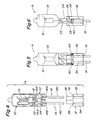
- FIGURE 4 illustrate an exploded view of an improved single ended, quartz wire lamp A having a quartz envelope 10 mountable within a ceramic base 12.
- a pair of three part leads 14 and 16 extend both inside the seal region of the envelope 10 and through the base 12 as is shown in FIGURE 5 so as to be partially exposed below the base for connection to a power source whereby the leads function as both connectors to the filament as well as base pins connectable to the power source.
- the quartz envelope 10 includes a filament 15 with a first end 18 and a second end 20 (via an extension in this embodiment). Both ends 18 and 20 are hermetically sealed within a seal region 22 of the envelope 10 when the envelope shape is formed from a standard quartz tube.
- the seal region as shown from the side in FIG. 6 is coplanar quartz wire to the filament envelope portion of the lamp which has a voluminous shape for housing the filament 16.
- the seal region 22 includes improved seal definition as supplied by a well-defined embossed rail 24 in the seal region 22.
- the embossed rail is a raised portion resulting from the heat sealing process where the quartz is raised above its softening temperature to approximately 2000°C.
- the molding or pressing in unison with high temperatures allows the quartz tube to be reshaped and closed with the ends of the filament 18 and 20 extending therethrough whereby the mold is contoured so as to leave the well defined embossed rail 24 which is always a constant, known distance from the filament.
- each of the three part leads 14 and 16 consist of an inner molybdenum foil 14A and 16A, respectively, an outer molybdenum wire 14B and 16B, respectively, and an outer nickel wire 14C and 16C, respectively, plated or coated resulting in outer leads of a standard dimension, such as 0.060 inch (1.5 mm) diameter as described above.
- the inner foil portions 14A and 16A of the three part leads 14 and 16 are welded to or otherwise electrically connected to the ends of the filament 18 and 20, and are flat planar sheets hermetically sealed in the seal region 22.
- the ceramic base 12 has an envelope receiving slot 26 defined by four sides, two 28 and 30 are taller than the other two 32 and 34 as is shown in FIG. 6.
- the base is manufactured out of a ceramic material so as to function in an insulative and non-conductive manner.
- the improved single ended quartz projection lamp assembly a in easily assembled using less parts and assembly steps than the prior art. Assembly is specifically as follows, wire lamp leads 14 and 16 are electrically connected, typically by welding, to the filament 16 via ends 18 and 20. More specifically, prior to sealing of the envelope, the inner molybdenum leads 14A and 16A are placed in the to-be-sealed region after king welded to the filament ends.
- the wire lamp outer leads specifically, the molybdenum and nickel leads 14B, 16B, 14C and 16C which were previously welded together, are inserted through a pair of corresponding holes 36 and 38 in the ceramic base 12. The base 12 is pushed up over the wire lamp seal region 22 until stopped by embossed seal rail 24.
- the base length is designed such that correct light center length (LCL) as described above is achieved with the base 12 pushed up to the embossed seal rail 24.
- LCL light center length
- Cement 40 is applied inside of the base 12 around the wire lamp leads 14 and 16 up to the wire lamp seal region 22.
- the seating of the ceramic base 12 against the embossed seal rail 24 always results in correct light center length and alignment between the filament 16 and the base 12. This proper light center length and alignment eliminates need for wire lamp adjustment to locate the filament 16 over the base 12.
- the lamp assembly A is then heated to set the cement. Finally, the ends of the leads 14 and 16 are shaped to round off and eliminate any sharp edges and form standard base pins.
- one of the central features of the new design and assembly process invention is the use of a more advanced quartz inner lamp with improved seal definition, an embossed rail in the seal, better control of filament location with respect to the seal and the base, and two layer molybdenum-nickel outer lead wires rather than use of separate leads between the wire lamp and base. Also, nickel outer lead wires eliminate need for separate base pins staked in the ceramic base. Finally, a smaller ceramic base is used that requires far less cement, both of which enable more effective cooling of the lamp while operated in projection equipment resulting in the use of higher wattage lamps with more light output as is always desired in all projection applications.
Landscapes
- Vessels And Coating Films For Discharge Lamps (AREA)
- Common Detailed Techniques For Electron Tubes Or Discharge Tubes (AREA)
- Projection Apparatus (AREA)
Applications Claiming Priority (2)
| Application Number | Priority Date | Filing Date | Title |
|---|---|---|---|
| US08/672,791 US6011353A (en) | 1996-06-28 | 1996-06-28 | Design and cooling of single ended quartz projection lamps |
| US672791 | 1996-06-28 |
Publications (2)
| Publication Number | Publication Date |
|---|---|
| EP0817244A2 true EP0817244A2 (de) | 1998-01-07 |
| EP0817244A3 EP0817244A3 (de) | 1999-05-12 |
Family
ID=24700009
Family Applications (1)
| Application Number | Title | Priority Date | Filing Date |
|---|---|---|---|
| EP97304683A Withdrawn EP0817244A3 (de) | 1996-06-28 | 1997-06-27 | Einseitig gesockelte Quartz-Projektionslampe |
Country Status (11)
| Country | Link |
|---|---|
| US (2) | US6011353A (de) |
| EP (1) | EP0817244A3 (de) |
| JP (1) | JPH1083799A (de) |
| KR (1) | KR980007848A (de) |
| CN (1) | CN1085400C (de) |
| BR (1) | BR9703793A (de) |
| CA (1) | CA2205852A1 (de) |
| HU (1) | HU221579B (de) |
| MX (1) | MX9704883A (de) |
| PL (1) | PL183221B1 (de) |
| TW (1) | TW381297B (de) |
Cited By (1)
| Publication number | Priority date | Publication date | Assignee | Title |
|---|---|---|---|---|
| WO2007090762A1 (de) * | 2006-02-07 | 2007-08-16 | Osram Gesellschaft mit beschränkter Haftung | Entladungslampe mit vergossenem sockel |
Families Citing this family (6)
| Publication number | Priority date | Publication date | Assignee | Title |
|---|---|---|---|---|
| EP1080994B1 (de) | 1999-09-02 | 2005-11-30 | Honda elesys Co., Ltd. | Vorrichtung und Verfahren zur Sitzbelegungserkennung durch im Sitz eingerichtete Elektroden |
| US6515421B2 (en) * | 1999-09-02 | 2003-02-04 | General Electric Company | Control of leachable mercury in fluorescent lamps |
| TW572348U (en) * | 2001-01-15 | 2004-01-11 | Shining Blick Enterprises Co | Safety protection device for bulb with polarity leads directly bonded to conductive wires |
| DE10145232A1 (de) * | 2001-09-13 | 2003-04-10 | Patent Treuhand Ges Fuer Elektrische Gluehlampen Mbh | Sockelkitt für elektrische Lampen |
| USD757305S1 (en) * | 2015-02-27 | 2016-05-24 | Osram Sylvania Inc. | Lamp capsule with coating |
| CN109140294A (zh) * | 2018-08-02 | 2019-01-04 | 江门市辉翔灯饰有限公司 | 新型抱箍投射灯 |
Family Cites Families (14)
| Publication number | Priority date | Publication date | Assignee | Title |
|---|---|---|---|---|
| US1760693A (en) * | 1925-10-05 | 1930-05-27 | Westinghouse Lamp Co | Prefocused incandescent electric lamp |
| US3469140A (en) * | 1967-02-13 | 1969-09-23 | Westinghouse Electric Corp | Single-ended electric incandescent lamp with improved base and terminal structure,and method of assembly |
| US3431540A (en) * | 1968-01-30 | 1969-03-04 | Sylvania Electric Prod | Lamp base |
| US3496403A (en) * | 1968-03-28 | 1970-02-17 | Westinghouse Electric Corp | Single-ended electric incandescent lamp and mount assembly therefor |
| GB1391704A (en) * | 1972-04-14 | 1975-04-23 | Thorn Electrical Ind Ltd | Lamp pinch seals |
| US3974370A (en) * | 1974-09-16 | 1976-08-10 | General Electric Company | Prefocused lamp base and fixture |
| US3997808A (en) * | 1975-06-30 | 1976-12-14 | General Electric Company | Mounting for single-ended lamp |
| JPS5444374A (en) * | 1977-09-14 | 1979-04-07 | Toshiba Corp | Halogen lamp |
| US4243907A (en) * | 1979-07-05 | 1981-01-06 | Gte Products Corporation | Lamp having reduced width press-seal |
| US4287448A (en) * | 1979-07-16 | 1981-09-01 | General Electric Company | Mechanical stop means for a prefocused plastic PAR lamp |
| GB8302494D0 (en) * | 1983-01-29 | 1983-03-02 | Emi Plc Thorn | Tungsten halogen incandescent lamps |
| US4568854A (en) * | 1983-10-27 | 1986-02-04 | Gte Products Corporation | Tungsten halogen lamp with heat-dissipating base |
| US4785218A (en) * | 1987-07-13 | 1988-11-15 | Gte Products Corporation | Tungsten halogen lamp base |
| US4985656A (en) * | 1989-09-05 | 1991-01-15 | Gte Products Corporation | Lamp with re-enforced tubular base pins |
-
1996
- 1996-06-28 US US08/672,791 patent/US6011353A/en not_active Expired - Fee Related
-
1997
- 1997-05-22 CA CA002205852A patent/CA2205852A1/en not_active Abandoned
- 1997-05-26 TW TW086107085A patent/TW381297B/zh active
- 1997-06-25 PL PL97320770A patent/PL183221B1/pl unknown
- 1997-06-26 JP JP9169362A patent/JPH1083799A/ja not_active Withdrawn
- 1997-06-27 HU HU9701110A patent/HU221579B/hu not_active IP Right Cessation
- 1997-06-27 EP EP97304683A patent/EP0817244A3/de not_active Withdrawn
- 1997-06-27 MX MX9704883A patent/MX9704883A/es not_active IP Right Cessation
- 1997-06-27 KR KR1019970028326A patent/KR980007848A/ko not_active Withdrawn
- 1997-06-27 CN CN97114035A patent/CN1085400C/zh not_active Expired - Fee Related
- 1997-06-30 BR BR9703793A patent/BR9703793A/pt active Search and Examination
-
1999
- 1999-12-10 US US09/460,176 patent/US6203392B1/en not_active Expired - Fee Related
Cited By (2)
| Publication number | Priority date | Publication date | Assignee | Title |
|---|---|---|---|---|
| WO2007090762A1 (de) * | 2006-02-07 | 2007-08-16 | Osram Gesellschaft mit beschränkter Haftung | Entladungslampe mit vergossenem sockel |
| CN101379587B (zh) * | 2006-02-07 | 2010-10-13 | 奥斯兰姆有限公司 | 具有浇铸的灯头的放电灯 |
Also Published As
| Publication number | Publication date |
|---|---|
| PL320770A1 (en) | 1998-01-05 |
| US6203392B1 (en) | 2001-03-20 |
| PL183221B1 (pl) | 2002-06-28 |
| CA2205852A1 (en) | 1997-12-28 |
| HU221579B (hu) | 2002-11-28 |
| KR980007848A (ko) | 1998-03-30 |
| HU9701110D0 (en) | 1997-08-28 |
| MX9704883A (es) | 1997-12-31 |
| HUP9701110A3 (en) | 2000-08-28 |
| CN1176363A (zh) | 1998-03-18 |
| CN1085400C (zh) | 2002-05-22 |
| HUP9701110A2 (hu) | 1998-04-28 |
| US6011353A (en) | 2000-01-04 |
| EP0817244A3 (de) | 1999-05-12 |
| TW381297B (en) | 2000-02-01 |
| JPH1083799A (ja) | 1998-03-31 |
| BR9703793A (pt) | 1999-01-19 |
Similar Documents
| Publication | Publication Date | Title |
|---|---|---|
| US5239226A (en) | Replaceable lamp assembly for automotive headlamps | |
| EP0129868B1 (de) | Auswechselbare Lampeneinheit die die Dichtung und die Justierung der Lampe gewährleistet und Kraftfahrzeugscheinwerfer mit solcher Lampeneinheit | |
| JPH09213208A (ja) | 電 球 | |
| US6244737B1 (en) | Electric lamp | |
| US7002285B2 (en) | Discharge lamp with bulb fixture arrangement and method for manufacturing the same | |
| US6203392B1 (en) | Single ended quartz projection lamp | |
| HU221363B1 (en) | Electric lamp | |
| JPH06243779A (ja) | 放電ランプ装置用絶縁性ベース | |
| KR100473699B1 (ko) | 전기백열램프를제조하기위한방법 | |
| US4795388A (en) | Method of making replaceable lamp unit for use in automobile headlight | |
| US5130911A (en) | Two piece lamp holder | |
| US4719543A (en) | Replaceable lamp unit for automobile headlight | |
| JPH0660856A (ja) | リフレクタ付電球 | |
| EP0179524A1 (de) | Elektrische Lampe mit Sockel | |
| US5936333A (en) | Radiation source with high-temperature resistant base and connection terminals, and method of its manufacture | |
| CN1322532C (zh) | 白炽电灯及插座组件 | |
| EP0604924A1 (de) | Mikrowellen gespeiste Kfz-Lampe | |
| EP0517299A2 (de) | Gesockelte Lampe/Reflektoreinheit | |
| JP2849276B2 (ja) | 放電ランプ装置 | |
| US4574217A (en) | Incandescent lamp and base | |
| US20030117056A1 (en) | Compact low-pressure discharge lamp | |
| EP0833415B1 (de) | Lampenfassung mit kreisförmig angeformten Anschlussverbindungen | |
| US6919671B2 (en) | Compact low-pressure discharge lamp | |
| US7391146B2 (en) | Halogen incandescent lamp | |
| US5127864A (en) | Method of making a double ended lamp |
Legal Events
| Date | Code | Title | Description |
|---|---|---|---|
| PUAI | Public reference made under article 153(3) epc to a published international application that has entered the european phase |
Free format text: ORIGINAL CODE: 0009012 |
|
| AK | Designated contracting states |
Kind code of ref document: A2 Designated state(s): BE DE ES FR GB IT NL |
|
| PUAL | Search report despatched |
Free format text: ORIGINAL CODE: 0009013 |
|
| AK | Designated contracting states |
Kind code of ref document: A3 Designated state(s): AT BE CH DE DK ES FI FR GB GR IE IT LI LU MC NL PT SE |
|
| 17P | Request for examination filed |
Effective date: 19991112 |
|
| AKX | Designation fees paid |
Free format text: BE DE ES FR GB IT NL |
|
| 17Q | First examination report despatched |
Effective date: 20021204 |
|
| STAA | Information on the status of an ep patent application or granted ep patent |
Free format text: STATUS: THE APPLICATION IS DEEMED TO BE WITHDRAWN |
|
| 18D | Application deemed to be withdrawn |
Effective date: 20030415 |