EP0817332A1 - Ein Herstellungsverfahren für Kommutatoren elektrischer Maschinen - Google Patents
Ein Herstellungsverfahren für Kommutatoren elektrischer Maschinen Download PDFInfo
- Publication number
- EP0817332A1 EP0817332A1 EP97110639A EP97110639A EP0817332A1 EP 0817332 A1 EP0817332 A1 EP 0817332A1 EP 97110639 A EP97110639 A EP 97110639A EP 97110639 A EP97110639 A EP 97110639A EP 0817332 A1 EP0817332 A1 EP 0817332A1
- Authority
- EP
- European Patent Office
- Prior art keywords
- segments
- ring
- strip
- commutator
- electrically
- Prior art date
- Legal status (The legal status is an assumption and is not a legal conclusion. Google has not performed a legal analysis and makes no representation as to the accuracy of the status listed.)
- Withdrawn
Links
- 238000004519 manufacturing process Methods 0.000 title claims description 4
- 238000000034 method Methods 0.000 claims abstract description 13
- 239000000463 material Substances 0.000 claims abstract description 9
- 238000003754 machining Methods 0.000 claims abstract description 8
- 239000004033 plastic Substances 0.000 claims abstract description 7
- 229920003023 plastic Polymers 0.000 claims abstract description 7
- 239000004020 conductor Substances 0.000 claims abstract description 6
- RYGMFSIKBFXOCR-UHFFFAOYSA-N Copper Chemical compound [Cu] RYGMFSIKBFXOCR-UHFFFAOYSA-N 0.000 claims abstract description 5
- 238000005452 bending Methods 0.000 claims abstract description 5
- 229910052802 copper Inorganic materials 0.000 claims abstract description 5
- 239000010949 copper Substances 0.000 claims abstract description 5
- 239000011810 insulating material Substances 0.000 claims abstract description 4
- 239000012777 electrically insulating material Substances 0.000 claims description 5
- 238000004804 winding Methods 0.000 claims description 2
- 210000002105 tongue Anatomy 0.000 description 3
- 239000002184 metal Substances 0.000 description 2
- 229910052751 metal Inorganic materials 0.000 description 2
- 238000000465 moulding Methods 0.000 description 2
- 238000004873 anchoring Methods 0.000 description 1
- 238000010276 construction Methods 0.000 description 1
- 238000005520 cutting process Methods 0.000 description 1
- 238000001125 extrusion Methods 0.000 description 1
- 238000001746 injection moulding Methods 0.000 description 1
- 239000002991 molded plastic Substances 0.000 description 1
- 238000002360 preparation method Methods 0.000 description 1
- 239000007858 starting material Substances 0.000 description 1
Images


Classifications
-
- H—ELECTRICITY
- H01—ELECTRIC ELEMENTS
- H01R—ELECTRICALLY-CONDUCTIVE CONNECTIONS; STRUCTURAL ASSOCIATIONS OF A PLURALITY OF MUTUALLY-INSULATED ELECTRICAL CONNECTING ELEMENTS; COUPLING DEVICES; CURRENT COLLECTORS
- H01R43/00—Apparatus or processes specially adapted for manufacturing, assembling, maintaining, or repairing of line connectors or current collectors or for joining electric conductors
- H01R43/06—Manufacture of commutators
- H01R43/08—Manufacture of commutators in which segments are not separated until after assembly
Definitions
- the present invention relates to a method of manufacturing a commutator for electrical machines.
- the object of the present invention is to provide a method which can be implemented easily and cheaply and which requires the use of materials which are inexpensive and easily-obtained.
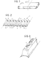
- the method according to the invention provides for a strip of electrically-conducting material, typically metal, such as copper in particular, as the starting material.
- This strip can be obtained, for example from a coil, suitably straightened.
- the strip 1 is subjected to a plastic deformation step (coining) so as to form therein (Figure 2) a plurality of parallel grooves 2 between which a corresponding plurality of equally-spaced transverse segments 3 is defined, the segments being interconnected on a principal face of the strip by thinner integral connecting bridges 4.
- a loop 5 and a tongue 6 are advantageously formed by an incision step in the top face of each segment 3, projecting from the surface of this face ( Figure 3).
- the strip 1 is cut into portions each of which includes a number of transverse segments 3 equal to the desired number of bars of the commutator to be produced.
- Each portion of strip thus produced is then bent so as to form a ring 7 ( Figure 4) with the segments 3 spaced equiangularly.
- the connecting bridges 4 extend on the periphery of the ring 7 and the loops or hooks 5 and tongues 6 extend radially inwardly of the ring (see also Figure 5).
- end portions of the segments 3 are bent radially outwardly as can be seen in Figures 6 and 7, possibly after preliminary partial cutting of the connecting bridges 4.
- the bent ends 3a of the segments 3 of the ring are then cut and opened out so as to form a corresponding plurality of essentially coplanar forks 8.
- the ring 7 is then incorporated in an electrically-insulating plastics material, for example, by injection moulding.
- the electrically-insulating material indicated 9 in Figures 10 and 11, extends particularly into the grooves or spaces 2 defined between adjacent segments 3 of the ring.
- the moulded insulating material, together with the ring 7, forms a monolithic annular structure with a central axial duct 10, the axis of which coincides with the axis of the ring 7 (see Figures 10 and 11).
- the insulating material is advantageously but not necessarily moulded so as also to fill the spaces defined between adjacent forks 8 of the ring 7 as well as between the prongs of the forks ( Figure 10).
- the hooks 5 and the tongues 6 of the segments 3 of the ring 7 advantageously act as elements for anchoring the segments firmly in the structure of moulded plastics material.
- the surface of the ring thus produced is then machined with the removal of material, for example, by turning, to give the ring 11 a perfectly smooth outer surface.
- this machining also removes the connecting bridges 4 so that, upon completion of the machining, the segments 3 are separated and are electrically-insulated from one another.
- Recesses 13 are hollowed out in the forks 8, also by further machining with the removal of material (Figure 12), to act as seats for the anchorage of the terminals of the windings of the electrical machine for which the commutator is intended.
- Figures 12 and 13 thus show the final appearance of the commutator upon completion of the method described above.
Landscapes
- Engineering & Computer Science (AREA)
- Manufacturing & Machinery (AREA)
- Motor Or Generator Current Collectors (AREA)
- Manufacture Of Motors, Generators (AREA)
- Laminated Bodies (AREA)
- Blow-Moulding Or Thermoforming Of Plastics Or The Like (AREA)
Applications Claiming Priority (2)
| Application Number | Priority Date | Filing Date | Title |
|---|---|---|---|
| IT96TO000580A IT1286155B1 (it) | 1996-07-05 | 1996-07-05 | Procedimento per la fabbricazione di un collettore a lamelle per macchine elettriche. |
| ITTO960580 | 1996-07-05 |
Publications (1)
| Publication Number | Publication Date |
|---|---|
| EP0817332A1 true EP0817332A1 (de) | 1998-01-07 |
Family
ID=11414761
Family Applications (1)
| Application Number | Title | Priority Date | Filing Date |
|---|---|---|---|
| EP97110639A Withdrawn EP0817332A1 (de) | 1996-07-05 | 1997-06-30 | Ein Herstellungsverfahren für Kommutatoren elektrischer Maschinen |
Country Status (2)
| Country | Link |
|---|---|
| EP (1) | EP0817332A1 (de) |
| IT (1) | IT1286155B1 (de) |
Citations (3)
| Publication number | Priority date | Publication date | Assignee | Title |
|---|---|---|---|---|
| DE1951208U (de) * | 1964-04-03 | 1966-12-08 | Bosch Gmbh Robert | Rollkommutator fuer elektrische maschinen. |
| FR2458156A3 (fr) * | 1979-05-29 | 1980-12-26 | Dahl Paul Com Fab | Collecteur electrique cylindrique notamment pour rotor a grandes vitesses de rotation |
| US4559464A (en) * | 1983-06-27 | 1985-12-17 | General Electric Company | Molded commutator and method of manufacture |
-
1996
- 1996-07-05 IT IT96TO000580A patent/IT1286155B1/it active IP Right Grant
-
1997
- 1997-06-30 EP EP97110639A patent/EP0817332A1/de not_active Withdrawn
Patent Citations (3)
| Publication number | Priority date | Publication date | Assignee | Title |
|---|---|---|---|---|
| DE1951208U (de) * | 1964-04-03 | 1966-12-08 | Bosch Gmbh Robert | Rollkommutator fuer elektrische maschinen. |
| FR2458156A3 (fr) * | 1979-05-29 | 1980-12-26 | Dahl Paul Com Fab | Collecteur electrique cylindrique notamment pour rotor a grandes vitesses de rotation |
| US4559464A (en) * | 1983-06-27 | 1985-12-17 | General Electric Company | Molded commutator and method of manufacture |
Also Published As
| Publication number | Publication date |
|---|---|
| ITTO960580A0 (de) | 1996-07-05 |
| ITTO960580A1 (it) | 1998-01-05 |
| IT1286155B1 (it) | 1998-07-07 |
Similar Documents
| Publication | Publication Date | Title |
|---|---|---|
| EP0667657B1 (de) | Herstellungsverfahren eines ebenen Kohlesegmentkommutators. | |
| EP1241743B1 (de) | Zylindrischer Kommutator und Herstellungsverfahren | |
| EP0780029B1 (de) | Drehschalter | |
| CA1250884A (en) | Connection of tapered armature conductor to tapered commutator slot | |
| US7485998B2 (en) | Commutator | |
| US6958563B2 (en) | Riser commutators | |
| US6584673B2 (en) | Planar commutator segment attachment method and assembly | |
| EP0817332A1 (de) | Ein Herstellungsverfahren für Kommutatoren elektrischer Maschinen | |
| EP1237235A2 (de) | Ebener Kohlesegmentkommutator | |
| EP0325353A2 (de) | Ein Stromwender | |
| CN1068718C (zh) | 制作换向器的方法 | |
| JP3543387B2 (ja) | 回転電機の整流子およびその製造方法 | |
| US4369566A (en) | Process of producing front commutators for the rotors of direct current machines | |
| US5602438A (en) | Roll commutator for electric motors and dynamos, and method of manufacturing it | |
| EP0007186A1 (de) | Herstellungsverfahren von Stromwendern sowie gemäss diesen Verfahren hergestellter Stromwender | |
| EP0994554A3 (de) | Kommutator und Methode zu seiner Herstellung | |
| EP0379664A1 (de) | Kommutator für elektrische Maschinen | |
| KR100426237B1 (ko) | 자동차용 시동전동기의 분리형 정류자 | |
| JP2002136060A (ja) | 円筒型整流子及びその製造方法 | |
| GB2024667A (en) | Manufacture of commutators | |
| JP3212142B2 (ja) | 整流子およびその製造方法 | |
| JPH03124243A (ja) | 小型整流子及びその製造方法 | |
| JPH0819225A (ja) | 回転電機の整流子及びその製造方法 | |
| JPS62262383A (ja) | コンミュテ−タの製造方法 | |
| JPS643037B2 (de) |
Legal Events
| Date | Code | Title | Description |
|---|---|---|---|
| PUAI | Public reference made under article 153(3) epc to a published international application that has entered the european phase |
Free format text: ORIGINAL CODE: 0009012 |
|
| AK | Designated contracting states |
Kind code of ref document: A1 Designated state(s): DE ES FR GB SE |
|
| AX | Request for extension of the european patent |
Free format text: AL;LT;LV;RO;SI |
|
| 17P | Request for examination filed |
Effective date: 19980611 |
|
| AKX | Designation fees paid |
Free format text: DE ES FR GB SE |
|
| RBV | Designated contracting states (corrected) |
Designated state(s): DE ES FR GB SE |
|
| RAP1 | Party data changed (applicant data changed or rights of an application transferred) |
Owner name: DENSO MANUFACTURING ITALIA S.P.A. |
|
| STAA | Information on the status of an ep patent application or granted ep patent |
Free format text: STATUS: THE APPLICATION HAS BEEN WITHDRAWN |
|
| 18W | Application withdrawn |
Effective date: 20040614 |