EP0817736B1 - Hydraulische bremsanlage für kraftfahrzeuge - Google Patents
Hydraulische bremsanlage für kraftfahrzeuge Download PDFInfo
- Publication number
- EP0817736B1 EP0817736B1 EP95915845A EP95915845A EP0817736B1 EP 0817736 B1 EP0817736 B1 EP 0817736B1 EP 95915845 A EP95915845 A EP 95915845A EP 95915845 A EP95915845 A EP 95915845A EP 0817736 B1 EP0817736 B1 EP 0817736B1
- Authority
- EP
- European Patent Office
- Prior art keywords
- brake
- control unit
- brake system
- switching device
- electronic control
- Prior art date
- Legal status (The legal status is an assumption and is not a legal conclusion. Google has not performed a legal analysis and makes no representation as to the accuracy of the status listed.)
- Expired - Lifetime
Links
- 238000007789 sealing Methods 0.000 claims description 23
- 230000000694 effects Effects 0.000 claims description 4
- 238000012545 processing Methods 0.000 claims description 2
- 230000003213 activating effect Effects 0.000 claims 1
- 230000004069 differentiation Effects 0.000 claims 1
- 230000000881 depressing effect Effects 0.000 abstract 1
- 238000006073 displacement reaction Methods 0.000 description 20
- 238000001514 detection method Methods 0.000 description 3
- 239000012528 membrane Substances 0.000 description 3
- 238000000034 method Methods 0.000 description 3
- 230000005540 biological transmission Effects 0.000 description 2
- 238000011161 development Methods 0.000 description 2
- 241000196324 Embryophyta Species 0.000 description 1
- 241000209035 Ilex Species 0.000 description 1
- 230000007547 defect Effects 0.000 description 1
- 230000001419 dependent effect Effects 0.000 description 1
- 238000013461 design Methods 0.000 description 1
- 238000010586 diagram Methods 0.000 description 1
- 238000011156 evaluation Methods 0.000 description 1
- 230000001788 irregular Effects 0.000 description 1
- 239000002184 metal Substances 0.000 description 1
- 230000003014 reinforcing effect Effects 0.000 description 1
- 230000000284 resting effect Effects 0.000 description 1
- 238000005096 rolling process Methods 0.000 description 1
- 238000012549 training Methods 0.000 description 1
- 238000011144 upstream manufacturing Methods 0.000 description 1
- 238000009423 ventilation Methods 0.000 description 1
Images

Classifications
-
- B—PERFORMING OPERATIONS; TRANSPORTING
- B60—VEHICLES IN GENERAL
- B60T—VEHICLE BRAKE CONTROL SYSTEMS OR PARTS THEREOF; BRAKE CONTROL SYSTEMS OR PARTS THEREOF, IN GENERAL; ARRANGEMENT OF BRAKING ELEMENTS ON VEHICLES IN GENERAL; PORTABLE DEVICES FOR PREVENTING UNWANTED MOVEMENT OF VEHICLES; VEHICLE MODIFICATIONS TO FACILITATE COOLING OF BRAKES
- B60T8/00—Arrangements for adjusting wheel-braking force to meet varying vehicular or ground-surface conditions, e.g. limiting or varying distribution of braking force
- B60T8/32—Arrangements for adjusting wheel-braking force to meet varying vehicular or ground-surface conditions, e.g. limiting or varying distribution of braking force responsive to a speed condition, e.g. acceleration or deceleration
- B60T8/34—Arrangements for adjusting wheel-braking force to meet varying vehicular or ground-surface conditions, e.g. limiting or varying distribution of braking force responsive to a speed condition, e.g. acceleration or deceleration having a fluid pressure regulator responsive to a speed condition
- B60T8/48—Arrangements for adjusting wheel-braking force to meet varying vehicular or ground-surface conditions, e.g. limiting or varying distribution of braking force responsive to a speed condition, e.g. acceleration or deceleration having a fluid pressure regulator responsive to a speed condition connecting the brake actuator to an alternative or additional source of fluid pressure, e.g. traction control systems
- B60T8/4809—Traction control, stability control, using both the wheel brakes and other automatic braking systems
- B60T8/4827—Traction control, stability control, using both the wheel brakes and other automatic braking systems in hydraulic brake systems
- B60T8/4845—Traction control, stability control, using both the wheel brakes and other automatic braking systems in hydraulic brake systems using a booster or a master cylinder for traction control
- B60T8/4854—Traction control, stability control, using both the wheel brakes and other automatic braking systems in hydraulic brake systems using a booster or a master cylinder for traction control pneumatic boosters
-
- B—PERFORMING OPERATIONS; TRANSPORTING
- B60—VEHICLES IN GENERAL
- B60T—VEHICLE BRAKE CONTROL SYSTEMS OR PARTS THEREOF; BRAKE CONTROL SYSTEMS OR PARTS THEREOF, IN GENERAL; ARRANGEMENT OF BRAKING ELEMENTS ON VEHICLES IN GENERAL; PORTABLE DEVICES FOR PREVENTING UNWANTED MOVEMENT OF VEHICLES; VEHICLE MODIFICATIONS TO FACILITATE COOLING OF BRAKES
- B60T13/00—Transmitting braking action from initiating means to ultimate brake actuator with power assistance or drive; Brake systems incorporating such transmitting means, e.g. air-pressure brake systems
- B60T13/10—Transmitting braking action from initiating means to ultimate brake actuator with power assistance or drive; Brake systems incorporating such transmitting means, e.g. air-pressure brake systems with fluid assistance, drive, or release
- B60T13/66—Electrical control in fluid-pressure brake systems
- B60T13/72—Electrical control in fluid-pressure brake systems in vacuum systems or vacuum booster units
-
- B—PERFORMING OPERATIONS; TRANSPORTING
- B60—VEHICLES IN GENERAL
- B60T—VEHICLE BRAKE CONTROL SYSTEMS OR PARTS THEREOF; BRAKE CONTROL SYSTEMS OR PARTS THEREOF, IN GENERAL; ARRANGEMENT OF BRAKING ELEMENTS ON VEHICLES IN GENERAL; PORTABLE DEVICES FOR PREVENTING UNWANTED MOVEMENT OF VEHICLES; VEHICLE MODIFICATIONS TO FACILITATE COOLING OF BRAKES
- B60T8/00—Arrangements for adjusting wheel-braking force to meet varying vehicular or ground-surface conditions, e.g. limiting or varying distribution of braking force
- B60T8/32—Arrangements for adjusting wheel-braking force to meet varying vehicular or ground-surface conditions, e.g. limiting or varying distribution of braking force responsive to a speed condition, e.g. acceleration or deceleration
- B60T8/321—Arrangements for adjusting wheel-braking force to meet varying vehicular or ground-surface conditions, e.g. limiting or varying distribution of braking force responsive to a speed condition, e.g. acceleration or deceleration deceleration
- B60T8/3255—Systems in which the braking action is dependent on brake pedal data
- B60T8/326—Hydraulic systems
- B60T8/3265—Hydraulic systems with control of the booster
-
- B—PERFORMING OPERATIONS; TRANSPORTING
- B60—VEHICLES IN GENERAL
- B60T—VEHICLE BRAKE CONTROL SYSTEMS OR PARTS THEREOF; BRAKE CONTROL SYSTEMS OR PARTS THEREOF, IN GENERAL; ARRANGEMENT OF BRAKING ELEMENTS ON VEHICLES IN GENERAL; PORTABLE DEVICES FOR PREVENTING UNWANTED MOVEMENT OF VEHICLES; VEHICLE MODIFICATIONS TO FACILITATE COOLING OF BRAKES
- B60T8/00—Arrangements for adjusting wheel-braking force to meet varying vehicular or ground-surface conditions, e.g. limiting or varying distribution of braking force
- B60T8/32—Arrangements for adjusting wheel-braking force to meet varying vehicular or ground-surface conditions, e.g. limiting or varying distribution of braking force responsive to a speed condition, e.g. acceleration or deceleration
- B60T8/321—Arrangements for adjusting wheel-braking force to meet varying vehicular or ground-surface conditions, e.g. limiting or varying distribution of braking force responsive to a speed condition, e.g. acceleration or deceleration deceleration
- B60T8/3255—Systems in which the braking action is dependent on brake pedal data
- B60T8/3275—Systems with a braking assistant function, i.e. automatic full braking initiation in dependence of brake pedal velocity
Definitions
- the invention relates to a hydraulic brake system for motor vehicles with an actuating unit consisting of a master brake cylinder and an upstream actuating unit that can be actuated by means of a brake pedal, with wheel brakes that are connected to the pressure chambers of the master brake cylinder with the interposition of an ABS hydraulic unit.
- Such a brake system is e.g. from DE-PS 42 08 496 known.
- the means for detecting the operating speed are in the known brake system Brake pedal assigned and preferably by an as Angle transmitter trained pedal position transmitter formed, while the above-mentioned switching device in the articulation area the actuating rod on the brake pedal and arranged by a Relative movement sensor is formed.
- sensor devices in the driver's footwell caused significant assembly costs, particularly on that are due to the fact that in the room mentioned a wiring harness must be relocated.
- the Function of the known sensor devices for example due to dirt or moisture occurring in the driver's footwell is affected.
- the travel sensor must be calibrated, i.e. its zero or starting point must be specified.
- a one-time calibration during the assembly of the device is not sufficient, however, because of wear and tear the operating time of the system may result in shifts.
- a one-off calibration of the displacement sensor a change in the mounting position of the displacement sensor in its attachment not recognized.
- the Electronic control unit has means that a continuous Enable displacement sensor calibration.
- the electronic Control unit the status data of the displacement sensor, the Brake light switch and the electrical switching device be fed continuously.
- the control unit is preferably a function of Switching status of the brake light switch and the electrical Switching device, in particular only if both the Brake light switch as well as the electrical switching device are in the unactuated state.
- a further increase in the functional reliability of the Brake system according to the invention is finally thereby achieved that the electronic control unit has means which is a recognition of the calibration carried out enable.
- the displacement sensor as proportional working sensor formed by the axial movement of the Vacuum brake booster moving wall can be actuated, the output signal of the actuation path is directly proportional to the movable wall and in the electronic control unit of a time-differentiating Processing is subjected.
- the displacement sensor is included preferably designed as a linear potentiometer.
- a particularly compact design of the invention is that the pneumatic valve by means of of the brake pedal actuable control valve of the Vacuum brake booster is formed, in addition by electromechanical, by means of electronic Control unit controllable means can be actuated.
- the electromechanical means are advantageous Training the subject of the invention by a Electromagnet as well as one with the electromagnet cooperating sealing seat of the control valve is formed, wherein the electromagnet as part of a power transmission Connection with the valve piston of the brake pedal is trained.
- the electrical switching device in a the control valve receiving control housing is arranged.
- the switching device preferably consists of an am Valve piston arranged microswitch and one in Control housing slidably guided actuator, that at rest of the vacuum brake booster on one stop attached to the amplifier housing.
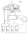
- the brake system according to the invention shown in Fig. 1 for Motor vehicles essentially consist of an actuation unit 1, an electronic control unit 8, Wheel brakes 12, 13, 14, 15, one between wheel brakes 12 to 15 and actuating unit 1 arranged ABS / hydraulic unit or Pressure modulator 9 and one with the electronic control unit 8 interacting ABS / ASR controller 7, the control signals generated for the pressure modulator 9.
- Not everyone Vehicle wheels shown are each a wheel sensor 16,17,18,19 assigned, which corresponds to the wheel speed Control signal is supplied to the ABS / ASR controller 7.
- the Actuating unit 1 in turn consists of a means a brake pedal 4 actuable pneumatic brake booster, preferably a vacuum brake booster 2, which a master brake cylinder 3, preferably a tandem master cylinder, is connected downstream, its pressure rooms, not shown via hydraulic lines 25, 26 with the pressure modulator 9 in Connect.
- a brake pedal 4 On the brake pedal 4 is an operating rod 27 coupled, the actuation of a merely schematically indicated control valve 5 allows the Development of a pneumatic differential pressure in the housing of the Vacuum brake booster 2 controls.
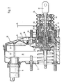
- the electronic control unit 8 controllable Electromagnet 22 (Fig. 2) enables external actuation of the control valve 5 regardless of one on the brake pedal 4 initiated actuation.
- a brake light switch that is operatively connected to the brake pedal 4 6 enables the detection of one on the Brake pedal 4 initiated operation while the Actuation speed by means of a sensor device is sensed, preferably by an analog working, assigned to the vacuum brake booster 2 Path sensor 11 is formed.
- the displacement sensor 11, its output signals are supplied to the electronic control unit and from her during the first period of braking as a basis for decision-making for active brake intervention can be evaluated, preferably as a linear Potentiometer be formed.
- the evaluation of the pedal start gradient takes place in the electronic control unit 8 by changing the time of the analog signals of the Potentiometer is formed. If the value determined in this way exceeds a predetermined threshold the control unit 8 a control signal for controlling the Control valve 5 actuating electromagnet 22.
- an electrical switching device 10 provided, which is only schematic in Fig. 1 is indicated.
- the amplifier housing 20 of the vacuum brake booster 2 shown in FIG. 1 through an axially movable wall 21 into a working chamber 30 and a vacuum chamber 31 divided.
- the axially movable Wall 21 consists of a membrane plate deep-drawn from sheet metal 24 and a flexible membrane 23 resting thereon, the between the outer periphery of the membrane plate 24 and the Amplifier housing 20 forms a roller fold as a seal.
- the control valve 5 which can be actuated by the actuating rod 27 is guided in a sealed manner in the amplifier housing 20, the control case 40 supporting the movable wall 21 housed and consists of a on the control housing 40th trained first sealing seat 41, one on one with the Actuating rod 27 connected valve piston 42 formed second sealing seat 43 and one with two sealing seats 41, 43 cooperating valve body 44.
- the working chamber 30 is with the vacuum chamber 31 via a laterally in Control housing 5 extending channel 28 connectable.
- a third sealing seat 45 is provided, the can be actuated by means of the electromagnet 22, which together is displaceable in the control housing 40 with the valve piston 42.
- the electromagnet 22 consists of one with the Valve piston 42 connected guide part 38 attached Coil 46 and a slidably disposed therein cylindrical armature 39, which with a in the control housing 40th sealed sleeve 29 in a force-transmitting Connection is formed on which the third sealing seat 45 is formed is, so that a transmission of the electromagnet 22nd third party applied to the third sealing seat 45 is made possible.
- the third sealing seat 45 is included compared to the second formed on the valve piston 42 Sealing seat 43 axially offset (see distance b).
- FIG. 2 there is aforementioned switching device 10 from a preferably on Valve piston 42 attached, having two switching positions Microswitch 35 and a microswitch 35 through actuating element actuating a translational movement 36, in a bore provided in the control housing 40 is guided and sealed with an amplifier housing Interacts stop, which bears the reference numeral 37 and for example by a radial collar of the rear Amplifier housing shell can be formed.
- an amplifier housing Interacts stop which bears the reference numeral 37 and for example by a radial collar of the rear Amplifier housing shell can be formed.
- the electronic control unit 8 receives continuously the state data of the displacement sensor 11, the Brake light switch 6 and the electrical switching device 10. The zero or starting point of the displacement sensor is then set or saved if neither the brake light switch 6 still the electrical switching device 10 is in the actuated Condition. From the moment the Switching state of the brake light switch 6 or the electrical Has changed switching device 10, the calibration value no longer changed.
- the procedure described is the 3 of the drawing.
- the measures described last allow one timely error detection of displacement sensor 11, brake light switch 6 and switching device 10. Another advantage is that the calibration performed is independent from the negative pressure prevailing in the amplifier housing, whereby general changes in the basic activity value or slight displacements of the displacement sensor 11 are compensated become. In addition, described by the dynamic Calibration Error in the absolute measured value of the displacement sensor 11 eliminated by irregular movements of the moving Wall 21 of the vacuum brake booster 2 arise can.
Landscapes
- Engineering & Computer Science (AREA)
- Transportation (AREA)
- Mechanical Engineering (AREA)
- Physics & Mathematics (AREA)
- Fluid Mechanics (AREA)
- Braking Systems And Boosters (AREA)
- Regulating Braking Force (AREA)
Abstract
Description
mit Radbremsen, die an die Druckräume des Hauptbremszylinders unter Zwischenschaltung eines ABS/Hydroaggregats angeschlossen sind,
mit einem mit dem Bremspedal zusammenwirkenden Bremslichtschalter,
mit einer elektrischen Schalteinrichtung, die eine Fahrerwunscherkennung im Sinne einer Zurücknahme der Bremswirkung ermöglicht,
mit einem Wegsensor zum Erfassen der Bremspedal-Betätigungsgeschwindigkeit,
sowie mit einer elektronischen Steuereinheit, der die elektrischen Signale des Bremslichtschalters, der elektrischen Schalteinrichtung, sowie des Wegsensors zugeführt werden und durch deren Ausgangssignale ein den Aufbau eines pneumatischen Differenzdruckes im Gehäuse des Unterdruckbremskraftverstärkers steuerndes pneumatisches Ventil unabhängig von der Betätigung durch den Fahrer im Sinne einer Vollbremsung aktivierbar ist.
- Fig. 1
- eine Ausführung der erfindungsgemäßen Bremsanlage in schematischer Darstellung;
- Fig. 2
- eine Ausführung des in der erfindungsgemäßen Bremsanlage nach Fig. 1 einsetzbaren pneumatischen Bremskraftverstärkers im Axialschnitt, teilweise weggebrochen; und
- Fig. 3 u.Fig. 4
- zwei Flußdiagramme, die in der elektronischen Steuereinheit bei der Kalibrierung stattfindende Funktionsabläufe darstellen.
- 1
- Betätigungeinheit
- 2
- Bremskraftverstärker
- 3
- Hauptbremszylinder
- 4
- Bremspedal
- 5
- Steuerventil
- 6
- Bremslichtschalter
- 7
- ABS/ASR-Regler
- 8
- Steuereinheit
- 9
- ABS-Hydroaggregat
- 10
- Schalteinrichtung
- 11
- Wegsensaor
- 12
- Radbremse
- 13
- Radbremse
- 14
- Radbremse
- 15
- Radbremse
- 16
- Radsensor
- 17
- Radsensor
- 18
- Radsensor
- 19
- Radsensor
- 20
- Verstärkergehäuse
- 21
- Wand
- 22
- Elektromagnet
- 23
- Rollmembran
- 24
- Membranteller
- 25
- Leitung
- 26
- Leitung
- 27
- Betätigungsstange
- 28
- Kanal
- 29
- Hülse
- 30
- Arbeitskammer
- 31
- Unterdruckkammer
- 32
- Querglied
- 33
- Anschlagfläche
- 34
- Kolbenstangenrückholfeder
- 35
- Mikroschalter
- 36
- Betätigungselement
- 37
- Anschlag
- 38
- Führungsteil
- 39
- Anker
- 40
- Steuergehäuse
- 41
- Dichtsitz
- 42
- Ventilkolben
- 43
- Dichtsitz
- 44
- Ventilkörper
- 45
- Dichtsitz
- 46
- Spule
Claims (12)
- Hydraulische Bremsanlage für Kraftfahrzeuge mit einer aus einem Hauptbremszylinder (3) sowie einem ihm vorgeschalteten, mittels eines Bremspedals (4) betätigbaren Unterdruckbremskraftverstärker (2) bestehenden Betätigungseinheit (1), mit Radbremsen (12,13,14,15), die an die Druckräume des Hauptbremszylinders (3) unter Zwischenschaltung eines ABS-Hydroaggregats (9) angeschlossen sind, mit einem mit dem Bremspedal (4) zusammenwirkenden Bremslichtschalter (6), mit einer elektrischen Schalteinrichtung (10), die eine Fahrerwunscherkennung im Sinne einer Zurücknahme der Bremswirkung ermöglicht, mit einem Wegsensor (11) zum Erfassen der Bremspedal-Betätigungsgeschwindigkeit, sowie mit einer elektronischen Steuereinheit (8), der die elektrischen Signale des Bremslichtschalters (6), der elektrischen Schalteinrichtung (10), sowie des Wegsensors (11) zugeführt werden und durch deren Ausgangssignale ein den Aufbau eines pneumatischen Differenzdruckes im Gehäuse des Unterdruckbremskraftverstärkers (2) steuerndes pneumatisches Ventil (5) unabhängig von der Betätigung durch den Fahrer im Sinne einer Vollbremsung aktivierbar ist, dadurch gekennzeichnet, daß die elektronische Steuereinheit (8) Mittel aufweist, die eine kontinuierliche Kalibrierung des Wegsensors (11) ermöglichen.
- Hydraulische Bremsanlage nach Anspruch 1, dadurch gekennzeichnet, daß der elektronischen Steuereinheit (8) die Zustandsdaten des Wegsensors (11), des Bremslichtschalters (6) sowie der elektrischen Schalteinrichtung (10) kontinuierlich zugeführt werden.
- Hydraulische Bremsanlage nach Anspruch 2, dadurch gekennzeichnet, daß der Kalibrierwert bzw. der Null-Punkt des Wegsensors (11)) in Abhängigkeit vom Schaltzustand des Bremslichtschalters (6) sowie der elektrischen Schalteinrichtung (10) in der elektronischen Steuereinheit (8) gespeichert wird.
- Hydraulische Bremsanlage nach Anspruch 3, dadurch gekennzeichnet, daß der Kalibrierwert nur dann gespeichert wird, wenn sich sowohl der Bremslichtschalter (6) als auch die elektrische Schalteinrichtung (10) in unbetätigtem Zustand befinden.
- Hydraulische Bremsanlage nach einem der Ansprüche 1 bis 4, dadurch gekennzeichnet, daß die elektronische Steuereinheit (8) Mittel aufweist, die eine Erkennung der durchgeführten Kalibrierung ermöglichen.
- Hydraulische Bremsanlage nach einem der Ansprüche 1 bis 5, dadurch gekennzeichnet, daß der Wegsensor (11) als proportional arbeitender Sensor ausgebildet ist, der durch axiale Bewegung der beweglichen Wand (21) des Unterdruckbremskraftverstärkers (2) betätigbar ist, wobei dessen Ausgangssignal dem Betätigungsweg der beweglichen Wand (21) direkt proportional ist und in der elektronischen Steuereinheit (8) einer zeitlich differenzierenden Verarbeitung unterworfen wird.
- Hydraulische Bremsanlage nach Anspruch 6, dadurch gekennzeichnet, daß der Wegsensor (11) als lineares Potentiometer ausgebildet ist.
- Hydraulische Bremsanlage nach Anspruch 6 oder 7, dadurch gekennzeichnet, daß das pneumatische Ventil durch das mittels des Bremspedals (4) betätigbare Steuerventil (5) des Unterdruckbremskraftverstärkers (2, gebildet ist, das zusätzlich durch elektromechanische, mittels der elektronischen Steuereinheit (8) ansteuerbare Mittel (22,29,45,46) betätigbar ist.
- Hydraulische Bremsanlage nach Anspruch 8, dadurch gekennzeichnet, daß die elektromechanischen Mittel durch einen Elektromagneten (22) sowie einen mit dem Elektromagneten (22) zusammenwirkenden Dichtsitz (45) des Steuerventils (5) gebildet sind.
- Hydraulische Bremsanlage nach Anspruch 9, dadurch gekennzeichnet, daß der Elektromagnet (22) als Bestandteil eines in kraftübertragender Verbindung mit dem Bremspedal (4) stehenden Ventilkolbens (42) ausgebildet ist.
- Hydraulische Bremsanlage nach einem der vorhergehenden Ansprüche, dadurch gekennzeichnet, daß die elektrische Schalteinrichtung (10) in einem das Steuerventil (5) aufnehmenden Steuergehäuse (40) angeordnet ist.
- Hydraulische Bremsanlage nach Anspruch 11, dadurch gekennzeichnet, daß die elektrische Schalteinrichtung (10) aus einem am Ventilkolben (42) angeordneten Mikroschalter (35) sowie einem im Steuergehäuse (40) verschiebbar geführten Betätigungselement (36) besteht, das in Ruhestellung des Unterdruckbremskraftverstärkers (2) an seinem verstärkergehäusefesten Anschlag (37) anliegt.
Applications Claiming Priority (2)
| Application Number | Priority Date | Filing Date | Title |
|---|---|---|---|
| DE4410699A DE4410699C2 (de) | 1994-03-28 | 1994-03-28 | Hydraulische Bremsanlage für Kraftfahrzeuge |
| PCT/EP1995/001237 WO1996031374A1 (de) | 1994-03-28 | 1995-04-05 | Hydraulische bremsanlage für kraftfahrzeuge |
Publications (2)
| Publication Number | Publication Date |
|---|---|
| EP0817736A1 EP0817736A1 (de) | 1998-01-14 |
| EP0817736B1 true EP0817736B1 (de) | 2002-08-14 |
Family
ID=25935148
Family Applications (1)
| Application Number | Title | Priority Date | Filing Date |
|---|---|---|---|
| EP95915845A Expired - Lifetime EP0817736B1 (de) | 1994-03-28 | 1995-04-05 | Hydraulische bremsanlage für kraftfahrzeuge |
Country Status (6)
| Country | Link |
|---|---|
| US (1) | US6554373B1 (de) |
| EP (1) | EP0817736B1 (de) |
| JP (1) | JP3874202B2 (de) |
| CZ (1) | CZ287189B6 (de) |
| DE (2) | DE4410699C2 (de) |
| WO (1) | WO1996031374A1 (de) |
Families Citing this family (21)
| Publication number | Priority date | Publication date | Assignee | Title |
|---|---|---|---|---|
| DE4410699C2 (de) * | 1994-03-28 | 2001-10-04 | Continental Teves Ag & Co Ohg | Hydraulische Bremsanlage für Kraftfahrzeuge |
| DE19541535A1 (de) * | 1995-11-08 | 1997-05-15 | Teves Gmbh Alfred | Verfahren zum Betrieb eines pneumatischen Bremskraftverstärkers |
| DE19601113A1 (de) * | 1996-01-13 | 1997-07-17 | Teves Gmbh Alfred | Unterdruckbremskraftverstärker für Kraftfahrzeuge |
| DE19601112A1 (de) * | 1996-01-13 | 1997-07-17 | Teves Gmbh Alfred | Unterdruckbremskraftverstärker für Kraftfahrzeuge |
| DE19620540C2 (de) * | 1996-05-22 | 2001-06-13 | Lucas Automotive Gmbh | Elektronisch steuerbare Bremsanlage |
| DE19722532B4 (de) * | 1997-05-30 | 2006-02-09 | Continental Teves Ag & Co. Ohg | Störunterdrückung am Membranwegsensor eines Bremskraftverstärkers |
| DE19729853C2 (de) * | 1997-07-11 | 2003-12-11 | Volkswagen Ag | Bremsvorwarnsystem |
| JP4026092B2 (ja) * | 1997-09-30 | 2007-12-26 | 株式会社日立製作所 | 制動装置 |
| US6033038A (en) * | 1998-06-22 | 2000-03-07 | General Motors Corporation | Brake control method having booster runout and pedal force estimation |
| DE19907338A1 (de) * | 1998-10-27 | 2000-05-04 | Continental Teves Ag & Co Ohg | Bremssystem und Verfahren zu seiner Steuerung |
| US7410038B2 (en) * | 2002-10-11 | 2008-08-12 | Svm Schultz Verwaltungs-Gmbh & Co. Kg | Locking unit |
| DE102004005107A1 (de) * | 2004-02-02 | 2005-08-18 | Lucas Automotive Gmbh | Bremskrafterzeuger für eine hydraulische Fahrzeugbremsanlage |
| KR20070006738A (ko) | 2004-02-02 | 2007-01-11 | 루카스 오토모티브 게엠베하 | 차량 유압 제동 장치용 제동력 발생기 |
| JP5135311B2 (ja) * | 2009-09-30 | 2013-02-06 | 日立オートモティブシステムズ株式会社 | 電動倍力装置 |
| US8521391B2 (en) | 2009-11-30 | 2013-08-27 | GM Global Technology Operations LLC | Methods and systems for brake pedal tuning and braking control in vehicles |
| DE102010029185B4 (de) | 2010-05-20 | 2022-03-17 | Bayerische Motoren Werke Aktiengesellschaft | Verfahren zum Betreiben eines Kraftfahrzeugs mit einer Unterdruckbremskraftverstärkungsvorrichtung |
| DE102010062163A1 (de) * | 2010-11-30 | 2012-05-31 | Continental Teves Ag & Co. Ohg | Vorrichtung zur Überwachung von Position und Bewegung eines Bremspedals |
| EP2828133B1 (de) * | 2012-03-20 | 2019-02-20 | Continental Teves AG & Co. OHG | Bremsgerät mit einer gerätefeder |
| JP5831486B2 (ja) * | 2013-03-29 | 2015-12-09 | トヨタ自動車株式会社 | ブレーキシステム |
| DE102015211430A1 (de) * | 2015-06-22 | 2016-12-22 | Robert Bosch Gmbh | Elektronisch schlupfregelbare Hilfskraftbremsanlage, insbesondere für ein Kraftfahrzeug |
| US12115904B2 (en) | 2023-02-13 | 2024-10-15 | Ford Global Techologies, Llc | Redundant system for brake light operation |
Family Cites Families (23)
| Publication number | Priority date | Publication date | Assignee | Title |
|---|---|---|---|---|
| FR2476577A1 (fr) * | 1980-02-22 | 1981-08-28 | Dba | Servomoteur d'assistance au freinage |
| DE3347819C2 (de) * | 1983-03-05 | 1985-09-26 | Adam Opel AG, 6090 Rüsselsheim | Bremslichtschalter für Kraftfahrzeuge |
| US4667471A (en) * | 1984-08-20 | 1987-05-26 | Allied Corporation | Brake booster for vehicular hill holder system |
| DE3625815A1 (de) * | 1986-07-30 | 1988-02-18 | Teves Gmbh Alfred | Kraftfahrzeugbremsvorrichtung |
| GB2197402B (en) * | 1986-11-06 | 1990-11-14 | Teves Gmbh Alfred | Brake system |
| FR2634524A1 (fr) * | 1988-07-22 | 1990-01-26 | Bendix France | Dispositif de detection de la position d'un organe mobile a l'interieur d'un organe fixe |
| DE3902215A1 (de) * | 1989-01-26 | 1990-08-02 | Teves Gmbh Alfred | Unterdruck-bremskraftverstaerker |
| DE3924327A1 (de) * | 1989-04-29 | 1990-10-31 | Teves Gmbh Alfred | Wegsensor zur messung mechanischer bewegungsgroessen |
| DE3920766C3 (de) * | 1989-06-24 | 2002-09-19 | Continental Teves Ag & Co Ohg | Unterdruckbremskraftverstärker für eine schlupfgeregelte Bremsanlage |
| DE4003957A1 (de) * | 1990-02-09 | 1991-08-14 | Teves Gmbh Alfred | Bremskraftverstaerker fuer bremssysteme mit antiblockier- und/oder antriebsschlupfregelung |
| DE59004242D1 (de) | 1989-12-02 | 1994-02-24 | Teves Gmbh Alfred | Bremskraftverstärker für bremssysteme mit antiblockier- und/oder antriebsschlupfregelung. |
| DE4004065A1 (de) * | 1990-02-10 | 1991-08-14 | Teves Gmbh Alfred | Blockiergeschuetzte kraftfahrzeugbremsanlage und verfahren zum betreiben einer solchen anlage |
| DE4015866C2 (de) * | 1990-05-17 | 2003-06-12 | Continental Teves Ag & Co Ohg | Schaltungsanordnung für eine blockiergeschützte Bremsanlage |
| FR2667368B1 (fr) * | 1990-09-28 | 1994-10-21 | Bendix Europ Services Tech | Servomoteur a depression. |
| DE4102497C1 (de) * | 1991-01-29 | 1992-05-07 | Mercedes-Benz Aktiengesellschaft, 7000 Stuttgart, De | |
| DE4116779C2 (de) * | 1991-05-23 | 2000-08-10 | Continental Teves Ag & Co Ohg | Unterdruck-Bremskraftverstärker |
| DE4133484A1 (de) * | 1991-10-09 | 1993-04-15 | Teves Gmbh Alfred | Bremsanlage mit blockierschutz und antriebsschlupfregelung |
| DE4208496C1 (de) * | 1992-03-17 | 1993-08-05 | Mercedes-Benz Aktiengesellschaft, 7000 Stuttgart, De | |
| CZ281175B6 (cs) * | 1992-11-13 | 1996-07-17 | Itt Automotive Europe Gmbh | Podtlakový posilovač brzd |
| DE4329140C1 (de) * | 1993-08-30 | 1994-12-01 | Daimler Benz Ag | Bremsdruck-Steuereinrichtung |
| DE4410699C2 (de) * | 1994-03-28 | 2001-10-04 | Continental Teves Ag & Co Ohg | Hydraulische Bremsanlage für Kraftfahrzeuge |
| DE4418270A1 (de) * | 1994-05-26 | 1995-11-30 | Teves Gmbh Alfred | Verfahren zum Regeln des Bremsdruckes |
| DE19503076A1 (de) * | 1995-02-01 | 1996-08-08 | Teves Gmbh Alfred | Verfahren zum Betreiben einer blockiergeschützten Kraftfahrzeugbremsanlage |
-
1994
- 1994-03-28 DE DE4410699A patent/DE4410699C2/de not_active Expired - Lifetime
-
1995
- 1995-04-05 DE DE59510327T patent/DE59510327D1/de not_active Expired - Lifetime
- 1995-04-05 EP EP95915845A patent/EP0817736B1/de not_active Expired - Lifetime
- 1995-04-05 US US08/930,166 patent/US6554373B1/en not_active Expired - Lifetime
- 1995-04-05 CZ CZ19973145A patent/CZ287189B6/cs not_active IP Right Cessation
- 1995-04-05 JP JP52989896A patent/JP3874202B2/ja not_active Expired - Lifetime
- 1995-04-05 WO PCT/EP1995/001237 patent/WO1996031374A1/de not_active Ceased
Also Published As
| Publication number | Publication date |
|---|---|
| EP0817736A1 (de) | 1998-01-14 |
| US6554373B1 (en) | 2003-04-29 |
| WO1996031374A1 (de) | 1996-10-10 |
| JPH11503090A (ja) | 1999-03-23 |
| DE4410699C2 (de) | 2001-10-04 |
| DE4410699A1 (de) | 1995-10-05 |
| DE59510327D1 (de) | 2002-09-19 |
| JP3874202B2 (ja) | 2007-01-31 |
| CZ287189B6 (en) | 2000-10-11 |
| CZ314597A3 (cs) | 1998-04-15 |
Similar Documents
| Publication | Publication Date | Title |
|---|---|---|
| DE4410699C2 (de) | Hydraulische Bremsanlage für Kraftfahrzeuge | |
| DE10238278B4 (de) | Elektronisches Bremssystem ohne Pumpeneinheit | |
| EP0435113B1 (de) | Fahrzeugbremsanlage | |
| EP0772539B1 (de) | Elektronisch regelbares blockiergeschütztes bremsbetätigungssystem | |
| EP2303655B1 (de) | Bremsanlage für kraftfahrzeuge | |
| EP0616932B1 (de) | Bremskraftverstärkersystem zum Regeln eines Bremsdruckes mit einem Bremskraftverstärker | |
| EP0742766B1 (de) | Hydraulische bremsanlage mit schlupfregelung | |
| DE4324205A1 (de) | Bremsanlage für Kraftfahrzeuge | |
| DE4401524A1 (de) | Hydraulische Bremsanlage mit Schlupfregelung | |
| DE4239386A1 (de) | Bremsanlage für Kraftfahrzeuge mit elektrischem Antrieb | |
| DE19750977B4 (de) | Bremsanlage | |
| EP0711695A2 (de) | Elektronisch gesteuerte Fahrzeugbremsanlage und Verfahren zu deren Betrieb | |
| EP0867350B1 (de) | Bremsregelungsanlage für Kraftfahrzeuge | |
| WO1995029830A1 (de) | Elektronisch regelbares bremsbetätigungssystem | |
| WO2012062393A1 (de) | Kolben-zylinder-vorrichtung und verfahren zur förderung einer hydraulikflüssigkeit unter druck zu einer betätigungseinrichtung, betätigungsvorrichtung für eine fahrzeugbremsanlage und ein verfahren zur betätigung einer betätigungsvorrichtung | |
| DE102017211955A1 (de) | Bremssystem mit einem Zusatzmodul | |
| EP0365629B1 (de) | Bremsdruckregelvorrichtung | |
| WO2010069656A1 (de) | Verfahren zur steuerung eines bremskraftverstärkers einer hydraulischen hilfskraft-fahrzeugbremsanlage | |
| EP0760765B1 (de) | Verfahren zum regeln des bremsdruckes | |
| DE3822260A1 (de) | Blockiergeschuetzte kraftfahrzeugbremsanlage | |
| EP2296948B1 (de) | Bremskraftverstärker für eine kraftfahrzeugbremsanlage und entsprechende kraftfahrzeugbremsanlage | |
| DE102017204559A1 (de) | Verfahren zum Betreiben eines Bremssystems und Bremssystem | |
| DE4028925A1 (de) | Betaetigungseinheit fuer hydraulische bremsanlagen | |
| DE2156307C2 (de) | Antiblockiervorrichtung für Kraftfahrzeuge | |
| EP0360013B1 (de) | Blockiergeschützte Kraftfahrzeugbremsanlage |
Legal Events
| Date | Code | Title | Description |
|---|---|---|---|
| PUAI | Public reference made under article 153(3) epc to a published international application that has entered the european phase |
Free format text: ORIGINAL CODE: 0009012 |
|
| 17P | Request for examination filed |
Effective date: 19971105 |
|
| AK | Designated contracting states |
Kind code of ref document: A1 Designated state(s): DE FR GB |
|
| RAP1 | Party data changed (applicant data changed or rights of an application transferred) |
Owner name: CONTINENTAL TEVES AG & CO. OHG |
|
| 17Q | First examination report despatched |
Effective date: 19990113 |
|
| GRAG | Despatch of communication of intention to grant |
Free format text: ORIGINAL CODE: EPIDOS AGRA |
|
| GRAG | Despatch of communication of intention to grant |
Free format text: ORIGINAL CODE: EPIDOS AGRA |
|
| GRAG | Despatch of communication of intention to grant |
Free format text: ORIGINAL CODE: EPIDOS AGRA |
|
| GRAH | Despatch of communication of intention to grant a patent |
Free format text: ORIGINAL CODE: EPIDOS IGRA |
|
| GRAH | Despatch of communication of intention to grant a patent |
Free format text: ORIGINAL CODE: EPIDOS IGRA |
|
| GRAA | (expected) grant |
Free format text: ORIGINAL CODE: 0009210 |
|
| AK | Designated contracting states |
Kind code of ref document: B1 Designated state(s): DE FR GB |
|
| REG | Reference to a national code |
Ref country code: GB Ref legal event code: FG4D Free format text: NOT ENGLISH |
|
| GBT | Gb: translation of ep patent filed (gb section 77(6)(a)/1977) |
Effective date: 20020814 |
|
| REF | Corresponds to: |
Ref document number: 59510327 Country of ref document: DE Date of ref document: 20020919 |
|
| ET | Fr: translation filed | ||
| PLBE | No opposition filed within time limit |
Free format text: ORIGINAL CODE: 0009261 |
|
| STAA | Information on the status of an ep patent application or granted ep patent |
Free format text: STATUS: NO OPPOSITION FILED WITHIN TIME LIMIT |
|
| 26N | No opposition filed |
Effective date: 20030515 |
|
| PGFP | Annual fee paid to national office [announced via postgrant information from national office to epo] |
Ref country code: FR Payment date: 20090421 Year of fee payment: 15 Ref country code: DE Payment date: 20090430 Year of fee payment: 15 |
|
| PGFP | Annual fee paid to national office [announced via postgrant information from national office to epo] |
Ref country code: GB Payment date: 20090424 Year of fee payment: 15 |
|
| PG25 | Lapsed in a contracting state [announced via postgrant information from national office to epo] |
Ref country code: DE Free format text: LAPSE BECAUSE OF THE APPLICANT RENOUNCES Effective date: 20100108 |
|
| GBPC | Gb: european patent ceased through non-payment of renewal fee |
Effective date: 20100405 |
|
| REG | Reference to a national code |
Ref country code: FR Ref legal event code: ST Effective date: 20101230 |
|
| PG25 | Lapsed in a contracting state [announced via postgrant information from national office to epo] |
Ref country code: GB Free format text: LAPSE BECAUSE OF NON-PAYMENT OF DUE FEES Effective date: 20100405 |
|
| PG25 | Lapsed in a contracting state [announced via postgrant information from national office to epo] |
Ref country code: FR Free format text: LAPSE BECAUSE OF NON-PAYMENT OF DUE FEES Effective date: 20100430 |