EP0818268B1 - Schweisszangsteuerverfahren - Google Patents
Schweisszangsteuerverfahren Download PDFInfo
- Publication number
- EP0818268B1 EP0818268B1 EP97109594A EP97109594A EP0818268B1 EP 0818268 B1 EP0818268 B1 EP 0818268B1 EP 97109594 A EP97109594 A EP 97109594A EP 97109594 A EP97109594 A EP 97109594A EP 0818268 B1 EP0818268 B1 EP 0818268B1
- Authority
- EP
- European Patent Office
- Prior art keywords
- electrode chips
- workpiece
- positions
- contact
- electrode
- Prior art date
- Legal status (The legal status is an assumption and is not a legal conclusion. Google has not performed a legal analysis and makes no representation as to the accuracy of the status listed.)
- Expired - Lifetime
Links
Images


Classifications
-
- B—PERFORMING OPERATIONS; TRANSPORTING
- B23—MACHINE TOOLS; METAL-WORKING NOT OTHERWISE PROVIDED FOR
- B23K—SOLDERING OR UNSOLDERING; WELDING; CLADDING OR PLATING BY SOLDERING OR WELDING; CUTTING BY APPLYING HEAT LOCALLY, e.g. FLAME CUTTING; WORKING BY LASER BEAM
- B23K11/00—Resistance welding; Severing by resistance heating
- B23K11/24—Electric supply or control circuits therefor
- B23K11/25—Monitoring devices
- B23K11/252—Monitoring devices using digital means
- B23K11/253—Monitoring devices using digital means the measured parameter being a displacement or a position
-
- B—PERFORMING OPERATIONS; TRANSPORTING
- B23—MACHINE TOOLS; METAL-WORKING NOT OTHERWISE PROVIDED FOR
- B23K—SOLDERING OR UNSOLDERING; WELDING; CLADDING OR PLATING BY SOLDERING OR WELDING; CUTTING BY APPLYING HEAT LOCALLY, e.g. FLAME CUTTING; WORKING BY LASER BEAM
- B23K11/00—Resistance welding; Severing by resistance heating
- B23K11/30—Features relating to electrodes
- B23K11/31—Electrode holders and actuating devices therefor
- B23K11/317—Equalizing; Balancing devices for electrode holders
Definitions
- the present invention relates to a welding gun control method according to the preamble of claim 1.
- Welding robots have prevalently been used for automatic spot welding in metal product manufacturing factories.
- the welding robot moves a welding gun sequentially to portions of a workpiece to be welded, holds the workpiece at a portion thereof to be welded between the tips of the electrode chips of the welding gun and supplies a welding current across the electrode chips while the workpiece is compressed between the electrode chips.
- An appropriate pressure must be applied to the portions of the workpiece to be welded to improve the reliability of welds.
- Reference 1 determines previously the relation between motor driving current for driving a servomotor for moving the electrode chips of a welding gun and pressure which is applied to the workpiece, moves the tips of the electrode chips to desired operating positions previously determined taking into consideration the thickness of the workpiece and a deflection in an arm supporting the welding gun, and then adjusts the positions of the electrode chips so that a motor driving current corresponding to a predetermined pressure is supplied to the servomotor.
- the prior art disclosed in Reference 2 corrects the interval between the electrode chips of a welding gun taking into consideration an average amount of wear of the electrode chips so that the interval between the electrode chips remains constant regardless of the wear of the electrode chips resulting from the repetition of a welding cycle.
- the prior art disclosed in Reference 3 monitors the motor driving current supplied to a servomotor for moving the electrode chips of a welding gun, detecting the positions of the tips of the electrode chips, and decides that the servomotor is loaded excessively by obstruction to the electrode chips by an obstacle if the motor driving current supplied to the servomotor increases before the tips of the electrode chips arrives at set positions determined taking into consideration the thickness of workpiece.
- a prior art technique disclosed in Reference 1 determines the desired operating positions of the electrode chips taking into consideration the thickness of the compressed workpiece and the deflection of the arm supporting the welding gun, and corrects the positions of the electrode chips on the basis of the difference between a pressure corresponding to the motor driving current supplied to the servomotor and a set pressure. Since the deflection of the arm to be caused when the workpiece is compressed between the electrode chips is taken into consideration before actually compressing the workpieces and before the arm is deflected, the operating positions of the tips of the electrode chips are advanced further toward the workpiece beyond positions where the tips of the electrode chips come into contact with the workpiece. Accordingly, the electrode chips collide at a relatively high speed against the workpiece and give relatively intense shocks to the workpiece.
- this prior art controls the welding gun so that the deceleration of the electrode chips is started a sufficiently long distance before positions where the electrode chips come into contact with the workpiece and the electrode chips come into contact gently with the workpiece.
- any concrete measures for achieving such control are not mentioned in Reference 1. Accordingly, the prior art disclosed in Reference 1 needs complex control operations to apply an appropriate pressure to the workpiece by correcting the positions of the tips of the electrode chips by a feedback control operation using an actual pressure applied to the workpiece.
- a prior art technique disclosed in Reference 2 corrects the interval between the electrode chips of a welding gun taking into consideration an average amount of wear of the electrode chips so that the interval between the electrode chips remains constant regardless of the wear of the electrode chips.
- nothing is described about measures for bringing the tips of the electrode chips into gentle contact with the workpiece and measures for controlling the electrode chips so that the workpiece is compressed between the electrode chips at a predetermined pressure.
- a prior art technique disclosed in Reference 3 is capable of detecting the collision of the electrode chips with an obstacle while the electrode chips held at an interval greater than the thickness of the workpiece are being moved through the detection of an abnormal increase in the motor driving current supplied to the servomotor.
- nothing is disclosed in Reference 3 about measures for bringing the tips of the electrode chips into gentle contact with the workpiece and measures for controlling the electrode chips so that the workpiece is compressed between the electrode chips at a predetermined pressure.
- the electrode chips cannot be controlled so that the electrode chips come into stable contact with the surfaces of the workpiece without giving intense shocks to the workpiece if different workpieces have different thicknesses, respectively, and the gaps between the electrode chips and different workpieces are different, when pressure to be applied by the electrode chips of a welding gun to the workpiece is controlled by the prior art techniques.
- the prior art techniques needs complex control operations including a control operation for correcting the projection of the electrode chips to control the electrode chips so that an appropriate pressure is applied to the workpieces.
- US-A-5 386 092 discloses a welding gun control method, in which starting positions for the electrode chips are set without using any reference position. According to the reference US'092 the speed to set the electrode chips in the starting positions is fast so that the electrode may have a great distance from the surfaces of the work piece prior to moving the electrode chips into the starting positions.
- US-A-4 841 113 discloses a welding control method in which in a first step the electrodes of a welding gun are brought into contact with each other so as to set a reference position for the electrode chips.
- WO 94 20254 A discloses a welding gun control method of which the features are also included in the preamble of claim 1.
- the reference positions where the tips of the electrode chips are in contact with each other are determined beforehand in a state where any workpiece is not held between the electrode chips, the desired starting positions of the electrode chips where the tips of the electrode chips are separated from each other by a distance corresponding to the thickness of the workpiece, and the positions of the electrode chips are controlled.
- the movement of the electrode chips to the desired starting positions is controlled in a first control mode in which the electrode chips are moved at the lower speed.
- the desired starting positions of the electrode chips are determined so that the tips of the electrode chips are not in contact with the workpiece to enable the quick movement of the electrode chips to the starting positions, taking into consideration difference in thickness between different workpieces.
- the movement of the electrode chips from the desired starting positions to the desired overshot positions is controlled in a second control mode in which the electrode chips are moved at the speed not higher than the predetermined speed, while the variation of the motor driving current supplied to the motor is monitored.
- the electrode chips are moved toward the desired overshot positions until the arrival of the electrode chips at positions where the electrode chips are in contact with the workpiece and the motor is overloaded is detected from the variation of the motor driving current supplied to the motor. Since the electrode chips come into contact with the workpiece at the low speed, the electrode chips will not give intense shocks to the workpiece.
- the electrode chips are able to be brought into contact with the workpiece in a short time even if the electrode chips are moved at a low speed.
- the motor is overloaded when the electrode chips arrive at the overshot positions, and then the motor driving current supplied to the motor is regulated to a motor driving current corresponding to a predetermined pressure. Therefore, an appropriate pressure is applied to the workpiece by the electrode chips. If difference in thickness between different workpieces is small, the starting positions may be positions where the electrode chips are in contact with the workpiece.
- a process of moving the electrode chips at the low speed from the starting positions to the contact positions where the electrode chips come into contact with the workpiece can be omitted, and the electrode chips can be moved at a stretch from the starting positions to the overshot positions at the high speed, which reduces welding cycle time.
- An operation for determining the reference positions where no workpiece is inserted between the electrode chips is one of the operations of the welding robot which can selectively be carried out.
- the operation for determining the reference positions where no workpiece is inserted between the electrode chips is one of the operations of the welding robot which can selectively be carried out, the operation for determining the reference positions can be repeated every several welding cycles, taking into account the amount of wear of the electrode chips, to compensate for a change in the reference positions due to the wear of the electrode chips.
- An optimum starting positions can be determined by correcting previously determined starting positions with reference to the distances between the starting positions and the contact positions traveled by the electrode chips.
- the welding cycle takes a long time because the electrode chips are moved at a low speed from the starting positions to the contact positions, and, if excessively short, the electrode chips may come into contact with the workpiece before the electrode chips arrive at the starting positions and may possibly give intense shocks to the workpiece if the workpiece to be welded includes those having a thickness greater than that used for determining the starting positions.
- the distance to be traveled by the electrode chips from the starting positions to the contact positions where the electrode chips will come into contact with the workpiece in the succeeding welding cycle is determined by correcting the distance traveled from the starting positions by the electrode chips before the electrode chips came into contact with the workpiece in the preceding welding cycle, the starting positions can be set so that the electrode chips come into contact with a workpiece after traveling an appropriate distance from the starting positions by learning control.
- a driving system for moving the electrode chips may include a compliance element.
- the driving system including the compliance element is able to absorb difference in thickness between different workpieces and to relieve shocks given to the workpiece by the electrode chips when the electrode chips come into contact with the workpiece.
- a welding gun 1 is provided at their forward end with an electrode chip 2a or 2b for spot welding, and a welding current supplied from a power source 3 and controlled by a welding current controller 4 is supplied through the electrode chip 2a, 2b to spot-weld plates 21 and 22 of a workpiece 20.
- a servomotor 6 drives a driving mechanism 5 to move the welding gun 1.
- An angular displacement of the output member of the servomotor 6 is detected by an encoder 7, and a motor driving current flowing through the servomotor 6 is detected by a current detector 8.
- the welding gun 1, the driving mechanism 5, the servomotor 6, the encoder 7 and the current detector 8 are components of a welding robot.
- the welding robot comprising a robot unit and a control unit provided with a robot CPU 10.
- the robot CPU 10 is connected through a system bus 11 to a servo CPU 12 for controlling the welding gun 1.
- the servo CPU 12 gives a position control signal for controlling the positions of the electrode chip 2a, 2b of the welding gun 1, and a force control signal for controlling pressure to be applied to a workpiece to a pressure controller 13.
- the pressure controller 13 controls a driver 14 according to control signals given thereto to control the operation of the servomotor 6.
- the output signal of the encoder 7 representing an angular displacement of the output member of the servomotor 6, and the output of the current detector 8 representing a motor driving current supplied to the servomotor 6 are given to the pressure controller 13 for feedback control.
- the robot CUP 10 is connected through the system bus 11 to a welding condition calculating unit 16 for calculating welding conditions on the bases of welding data read from a welding data storage device 15, and an input unit 17 for setting the welding robot in a teaching mode.
- the welding data storage device 15 stores data about positions of portions of a workpiece 20 (21 and 22) (Figs 2A-2C) to be welded, the thicknesses of the portions to be welded and such taught by teaching.
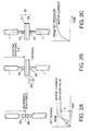
- Figs. 2A-2C illustrates a technical idea of the welding gun control method in the first embodiment to be carried out by the welding robot of Fig. 1.
- the indication of the encoder 7 combined with the servomotor 6 increases rapidly until the electrode chips 2a and 2b come into contact with each other, and then the indication of the encoder 7 changes slightly after the electrode chips 2a and 2b have come into contact with each other.
- the motor driving current supplied to the servomotor 6 increases sharply after the electrode chips 2a and 2b have come into contact with each other.
- the servomotor 7 provides a torque which produces a relatively low contact pressure between the electrode chips 2a and 2b.
- a set torque which produces the relatively low contact pressure of, for example 500 N, (50 kgf)
- the relation between the contact pressure applied to the workpiece by the electrode chips 2a and 2b, and the deflection of the arm after the motor driving current has reached a current value corresponding to the set torque is determined beforehand, and reference positions X for the electrode chips 2a and 2b are determined taking into consideration the deflection of the arm. The wear of the tips of the electrode chips 2a and 2b is taken into account when determining the reference positions X.
- starting positions X-d are determined taking into account the thickness d of the workpiece 20.
- the electrode chips 2a and 2b are moved to the starting positions X-d.
- the thickness d of the workpiece 20 is determined taking into consideration the respective thicknesses of plates 21 and 22 combined to form the workpiece 20, a gap between the plates 21 and 22, the deformation of the plates 21 and 22, and thickness distributions on the plates 21 and 22.
- the electrode chips 2a and 2b When moving the electrode chips 2a and 2b toward the workpiece 20, it is desirable to move the electrode chips 2a and 2b at a maximum speed to positions just before the starting positions X-d and to decelerate the electrode chips 2a and 2b at a maximum deceleration so that the electrode chips 2a and 2b are stopped at the starting positions X-d to move the electrode chips 2a and 2b to the starting positions X-d as quickly as possible. Then a compressing operation is carried out to move the electrode chips 2a and 2b to overshot positions. In an initial stage of the compressing operation, the electrode chips 2a and 2b are advanced gradually toward the workpiece 20.
- the motor driving current is monitored while the electrode chips 2a and 2b are moved at a very low speed nearly equal to zero toward the workpiece 20. Upon the arrival of the electrode chips 2a and 2b at contact positions where the tips of the electrode chips 2a and 2b come into contact with the surfaces of the workpiece 20, the motor driving current increases sharply.
- the electrode chips 2a and 2b are moved further toward the overshot positions at a high speed after the tips of the electrode chips 2a and 2b have come into contact with the surfaces of the workpiece 20, and then the motor driving current is adjusted so that the set pressure is applied to the workpiece 20 by the electrode chips 2a and 2b.
- the motor driving current and the respective positions of the electrode chips 2a and 2b are monitored to correct the desired starting positions X-d shown in Fig. 2B by a feedback control operation if the thicknesses of different workpieces 20 are distributed in a wide range or the gap between the plates 21 and 22 of the workpieces 20 is greater than that estimated.
- the starting positions X-d may be those where the electrode chips 2a and 2b come into contact with the surfaces of the workpiece 20, and the process of advancing the electrode chips 2a and 2b toward the workpiece 20 at a very low speed shown in Fig. 2B may be omitted.
- step a3 showing a welding gun control program to be carried out by the robot CPU 10 shown in Fig. 1, the robot CPU 10 starts a control operation in step a1.
- the reference positions X are measured in step a2.
- a query is made in step a3 to see if a simulated welding mode, i.e., a test welding mode in which a simulated welding operation is performed without using any workpiece and any welding current, is specified. If the response in step a3 is affirmative, step a4 is executed to set the thickness d of the workpiece 20 to zero.
- a simulated welding mode i.e., a test welding mode in which a simulated welding operation is performed without using any workpiece and any welding current
- step a6 welding data is read from the welding data storage device 15 in step a5, and starting positions X-d where the electrode chips 2a and 2b are separated from each other by a distance corresponding to the thickness d are determined in step a6.
- the starting position X-d may be determined so that the electrode chips 2a and 2b are in contact with the surfaces of the workpiece 20 when the same are moved to the starting positions X-d, respectively, if circumstances permit.
- step a7 the starting positions X-d are amended for the scattered thicknesses of workpieces and the scattered sizes of gaps in workpieces.
- step a8 the electrode chips 2a and 2b are moved to the starting positions X-d.
- step a9 overshot positions, i.e., positions where the tips of the electrode chips 2a and 2b are advanced beyond the surfaces of the workpiece 20 in a free state, are determined and the electrode chips 2a and 2b are moved to the overshot positions, respectively.
- the electrode chips 2a and 2b While the electrode chips 2a and 2b are moved from the starting positions X-d toward the overshot positions, the electrode chips 2a and 2b are moved at a low speed lower than a predetermined speed until the same arrives at contact positions where the electrode chips 2a and 2b come into contact with the workpiece 20, and then the electrode chips 2a and 2b are moved at a high speed higher than the predetermined speed from the contact positions to the overshot positions. The arrival of the electrode chips 2a and 2b at the contact positions is detected through the detection of the sharp change of the motor driving current.
- step a10 the motor driving current is adjusted to a predetermined current value corresponding to a predetermined pressure at which the workpiece 20 is to be compressed between the electrode chips 2a and 2b.
- step all a welding current is supplied across the electrode chips 2a and 2b for welding.
- a query is made in step a12 to see if the welding operation has been completed. If the response in step a12 is negative, the control procedure returns to step a3 and the welding operation is carried out to weld the next portion of the workpiece 20. If all the portions of the workpiece 20 to be welded are welded, the response in step a12 is affirmative, and the welding gun control program is ended in step a13.
- step a7 The distances traveled by the electrode chips 2a and 2b from the starting positions X-d/2 until the electrode chips 2a and 2b came into contact with the workpiece 20 are fed back to the CPU 10 to use the same as a correction in step a7. If the simulated welding mode is specified, any welding current is not supplied in step a11.
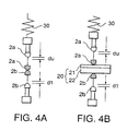
- FIG. 4A and 4B A welding gun control method in a second embodiment according to the present invention will be described hereinafter with reference to Figs. 4A and 4B illustrating a technical idea on which the welding gun control method in the second embodiment is based.
- Figs. 4A and 4B parts like or corresponding to those shown in Fig. 1 are designated by the same reference characters and the description thereof will be omitted to avoid duplication.
- a welding gun is provided with a pair of electrode chips 2a and 2b.
- a mechanical compliance 30 is included in a driving mechanism for driving the electrode chip 2a for movement.
- the mechanical compliance 30 absorbs difference in thickness between different workpieces and difference in size of gaps between plates 21 and 22 of different workpieces.
- the mechanical compliance 30 is able to absorb the displacement du of the upper electrode chip 2a as shown in Fig. 4A and 4B.
- a driving mechanism for driving the lower electrode chip 2b includes a mechanical compliance, not shown, capable of absorbing the displacement dl of the lower electrode chip 2b, increases du and dl respectively in the thicknesses of the plates 21 and 22 of the workpiece 20 can be absorbed.
- the compliance control operation of the servo CPU 12 may be used instead of the mechanical compliance 30 to absorb such difference in thickness between different workpieces.
- the present invention is applicable to controlling a welding gun provided with electrode chips which are moved in any direction other than the vertical direction to hold a workpiece for spot welding.
Landscapes
- Engineering & Computer Science (AREA)
- Mechanical Engineering (AREA)
- Resistance Welding (AREA)
Claims (4)
- Schweißpistolen-Steuerverfahren zum Steuern einer Schweißpistole (1), die in einem Schweißroboter enthalten ist, der eine Roboter-CPU (10) aufweist, die von der Roboter-CPU (10) angetrieben wird, die ein Paar Elektrodenchips (2a, 2b) besitzt, die von einem Motor (6) angetrieben werden und zwischen sich ein Werkstück (10) halten, und die das Werkstück (20) schweißt, wobei das Schweißpistolen-Steuerverfahren folgende Schritte aufweist:Einführen eines Werkstücks zwischen die paarweisen Elektrodenchips (2a, 2b), die von einander beabstandet sind;Einstellen von Startpositionen, an denen die paarweisen Elektrodenchips (2a, 2b) etwas gegenüber den zwischen die Elektrodenchips (2a, 2b) eingeführten Werkstücken (20) beabstandet sind, und Bewegen mindestens eines der paarweisen Elektrodenchips mit Hilfe des Motors (6), um die Elektrodenchips (2a, 2b) zu den Startpositionen zu bewegen;Einstellen von Überziel-Positionen, bei denen die Spitzen der paarweisen Elektrodenchips (2a, 2b) aufeinander zu über Kontaktpositionen hinaus vorgerückt werden, in denen die Spitzen der paarweisen Elektrodenchips (2a, 2b) mit der Oberfläche des Werkstücks (20) in Berührung stehen;Bewegen von mindestens einem der paarweisen Elektrodenchips durch den Motor (6) mit hoher Geschwindigkeit oberhalb einer vorbestimmten Geschwindigkeit, um die paarweisen Elektrodenchips aus den Kontaktpositionen in die Überziel-Positionen zu bewegen, wobei der Schritt des Bewegens beinhaltet, mindestens eines der Elektrodenchips von dem Motor (6) mit einer niedrigen Geschwindigkeit unterhalb der vorbestimmten Geschwindigkeit zu bewegen, damit die paarweisen Elektrodenchips (2a, 2b) von den Startpositionen in die Kontaktposition bewegt werden, dadurch gekennzeichnet, dass das Einstellen der Startpositionen auf der Grundlage von Referenzpositionen durchgeführt wird, in welchen die Elektrodenchips (2a, 2b) in Berührung miteinander stehen, und die von den Elektrodenchips ausgehend von den Startpositionen zu den Kontaktpositionen, an denen die Elektrodenchips mit dem Werkstück währen des nachfolgenden Zyklus in Berührung stehen, zurückzulegende Strecke dadurch bestimmt wird, dass die von den Elektrodenchips ausgehend von den Startpositionen vor dem In-Berührung-Kommen mit dem Werkstück zurückgelegte Strecke im vorhergehenden Schweißzyklus korrigiert wird.
- Verfahren nach Anspruch 1, weiterhin umfassend einen Schritt, bei dem die paarweisen Elektrodenchips miteinander in Berührung gebracht werden, um die Referenzpositionen für die paarweisen Elektrodenchips zu bestimmen.
- Verfahren nach Anspruch 1 oder 2, bei dem die Startpositionen dadurch bestimmt werden, dass die Referenzpositionen entsprechend der Dicke des Werkstücks (20) geändert werden.
- Verfahren nach einem der Ansprüche 1 bis 3, bei dem mindestens eines der paarweisen Elektrodenchips elastisch in Berührung mit dem Werkstück gebracht wird, wenn die paarweisen Elektrodenchips (2a, 2b) in Berührung mit dem Werkstück (20) gebracht werden.
Applications Claiming Priority (3)
| Application Number | Priority Date | Filing Date | Title |
|---|---|---|---|
| JP152636/96 | 1996-06-13 | ||
| JP15263696 | 1996-06-13 | ||
| JP15263696A JP3668325B2 (ja) | 1996-06-13 | 1996-06-13 | 溶接ガンの加圧制御方法 |
Publications (3)
| Publication Number | Publication Date |
|---|---|
| EP0818268A2 EP0818268A2 (de) | 1998-01-14 |
| EP0818268A3 EP0818268A3 (de) | 2002-01-23 |
| EP0818268B1 true EP0818268B1 (de) | 2005-05-04 |
Family
ID=15544735
Family Applications (1)
| Application Number | Title | Priority Date | Filing Date |
|---|---|---|---|
| EP97109594A Expired - Lifetime EP0818268B1 (de) | 1996-06-13 | 1997-06-12 | Schweisszangsteuerverfahren |
Country Status (4)
| Country | Link |
|---|---|
| US (1) | US5869799A (de) |
| EP (1) | EP0818268B1 (de) |
| JP (1) | JP3668325B2 (de) |
| DE (1) | DE69733174T2 (de) |
Families Citing this family (10)
| Publication number | Priority date | Publication date | Assignee | Title |
|---|---|---|---|---|
| JP3322826B2 (ja) * | 1997-08-13 | 2002-09-09 | ファナック株式会社 | サーボモータによる加圧制御方法及び装置 |
| US6225590B1 (en) * | 1998-05-26 | 2001-05-01 | Medar, Inc. | Method for determining a condition of a resistance spotwelding system or a workpiece in the system |
| FR2800656B1 (fr) * | 1999-11-08 | 2001-11-30 | Soudax Equipements | Procede de controle d'une operation de soudage mis en oeuvre par une machine de soudure par points |
| JP2002283059A (ja) * | 2001-03-26 | 2002-10-02 | Fanuc Ltd | サーボ式スポット溶接ガンの軸の基準位置設定方法及びロボット制御装置 |
| JP2004358508A (ja) * | 2003-06-04 | 2004-12-24 | Yaskawa Electric Corp | スポット溶接方法、スポット溶接機およびスポット溶接ロボット |
| JP4374039B2 (ja) * | 2007-06-14 | 2009-12-02 | ファナック株式会社 | スポット溶接システム及び溶接ガン閉速度調整方法 |
| JP4233584B2 (ja) * | 2007-06-18 | 2009-03-04 | ファナック株式会社 | スポット溶接ロボットの位置決め方法 |
| JP4870821B2 (ja) * | 2010-01-28 | 2012-02-08 | ファナック株式会社 | 溶接ワーク位置検出装置および溶接ワーク位置検出方法 |
| CN105517747B (zh) * | 2013-09-04 | 2018-01-05 | 杰富意钢铁株式会社 | 单面点焊装置 |
| JP2023132420A (ja) * | 2022-03-11 | 2023-09-22 | 三菱自動車工業株式会社 | スポット溶接装置及びスポット溶接方法 |
Family Cites Families (10)
| Publication number | Priority date | Publication date | Assignee | Title |
|---|---|---|---|---|
| CA1307835C (en) * | 1987-10-20 | 1992-09-22 | Akio Hamada | Welding control method and apparatus |
| US5412172A (en) * | 1990-10-08 | 1995-05-02 | Kabushiki Kaisha Sg | Spot welding machine |
| JP2506402Y2 (ja) * | 1991-10-11 | 1996-08-07 | 川崎重工業株式会社 | スポット溶接ロボット用制御装置 |
| US5386092A (en) * | 1991-11-04 | 1995-01-31 | Unitek Equipment Inc. | Fast response weld head |
| JP3207533B2 (ja) * | 1992-07-06 | 2001-09-10 | ファナック株式会社 | スポット溶接用制御装置及び制御方法 |
| DE4306492C1 (de) * | 1993-03-03 | 1994-07-21 | Wolfram Dr Ing Rennau | Schweißzangenregelung |
| JP3526888B2 (ja) * | 1993-04-30 | 2004-05-17 | 株式会社不二越 | 溶接ガン加圧力制御方法 |
| JPH06312274A (ja) * | 1993-04-30 | 1994-11-08 | Nachi Fujikoshi Corp | 溶接ガン位置補正方法 |
| JP3114440B2 (ja) * | 1993-07-22 | 2000-12-04 | 日産自動車株式会社 | スポット溶接装置 |
| JP3147603B2 (ja) * | 1993-08-25 | 2001-03-19 | トヨタ自動車株式会社 | スポット溶接ガンの加圧制御方法およびその装置 |
-
1996
- 1996-06-13 JP JP15263696A patent/JP3668325B2/ja not_active Expired - Fee Related
-
1997
- 1997-05-29 US US08/864,890 patent/US5869799A/en not_active Expired - Fee Related
- 1997-06-12 DE DE69733174T patent/DE69733174T2/de not_active Expired - Fee Related
- 1997-06-12 EP EP97109594A patent/EP0818268B1/de not_active Expired - Lifetime
Also Published As
| Publication number | Publication date |
|---|---|
| DE69733174D1 (de) | 2005-06-09 |
| EP0818268A3 (de) | 2002-01-23 |
| EP0818268A2 (de) | 1998-01-14 |
| DE69733174T2 (de) | 2005-11-17 |
| JPH106025A (ja) | 1998-01-13 |
| US5869799A (en) | 1999-02-09 |
| JP3668325B2 (ja) | 2005-07-06 |
Similar Documents
| Publication | Publication Date | Title |
|---|---|---|
| US20080297092A1 (en) | Machining robot control apparatus | |
| EP0813928B1 (de) | Verfahren und Vorrichtung zum Punktschweissen | |
| US5869799A (en) | Welding gun control method | |
| US20090069936A1 (en) | Control method for robots | |
| US20030111450A1 (en) | Arc welding apparatus and control method thereof | |
| EP1016490B1 (de) | Schweissverfahren | |
| CN111745277A (zh) | 机器人控制装置和机器人系统 | |
| CN100453237C (zh) | 焊接系统及自耗电极式焊接方法 | |
| JP3598683B2 (ja) | スポット溶接電極の最適位置制御方法 | |
| JP3322826B2 (ja) | サーボモータによる加圧制御方法及び装置 | |
| JP3337448B2 (ja) | スポット溶接ガンの位置決め方法 | |
| JP3200825B2 (ja) | アーク溶接ロボットの制御方法及び装置 | |
| JP2011206829A (ja) | 溶接ロボットのワイヤ突出長調整方法および装置 | |
| JPH10202371A (ja) | 溶接ガンのスパッタ検知方法及び溶接条件補正方法 | |
| JPH11216573A (ja) | フランジ部のスポット溶接方法及びその装置 | |
| JP2505394B2 (ja) | 産業用ロボットの加速度変化を利用した制御方法 | |
| JP4175316B2 (ja) | 溶接システムおよび溶接用ロボットの制御方法 | |
| JP3359012B2 (ja) | スポット溶接ロボット | |
| JP2682792B2 (ja) | 被溶接部材の端部検出方法 | |
| JP2655898B2 (ja) | 記憶・再生型アーク溶接ロボットの制御方法 | |
| JPH0825023B2 (ja) | 記憶・再生型自動溶接装置におけるワーク位置検出方法 | |
| JPH1085948A (ja) | スポット溶接制御装置 | |
| JPH07241676A (ja) | 自動溶接装置 | |
| JPS6171184A (ja) | 自動ア−ク溶接方法 | |
| JPH0242303B2 (de) |
Legal Events
| Date | Code | Title | Description |
|---|---|---|---|
| PUAI | Public reference made under article 153(3) epc to a published international application that has entered the european phase |
Free format text: ORIGINAL CODE: 0009012 |
|
| 17P | Request for examination filed |
Effective date: 19970612 |
|
| AK | Designated contracting states |
Kind code of ref document: A2 Designated state(s): AT BE CH DE DK ES FI FR GB GR IE IT LI LU MC NL PT SE Kind code of ref document: A2 Designated state(s): DE FR GB IT SE |
|
| RIN1 | Information on inventor provided before grant (corrected) |
Inventor name: SAKAMOTO, YOSHITAKA Inventor name: SUZUKI, SIKJI Inventor name: SUITA, KAZUTSUGU Inventor name: HIRAYAMA, SATORU Inventor name: ARASUNA, HITOSHI |
|
| PUAL | Search report despatched |
Free format text: ORIGINAL CODE: 0009013 |
|
| AK | Designated contracting states |
Kind code of ref document: A3 Designated state(s): AT BE CH DE DK ES FI FR GB GR IE IT LI LU MC NL PT SE |
|
| AKX | Designation fees paid |
Free format text: DE FR GB IT SE |
|
| 17Q | First examination report despatched |
Effective date: 20020913 |
|
| GRAP | Despatch of communication of intention to grant a patent |
Free format text: ORIGINAL CODE: EPIDOSNIGR1 |
|
| RIN1 | Information on inventor provided before grant (corrected) |
Inventor name: SAKAMOTO, YOSHITAKA Inventor name: SUZUKI, SIKJI Inventor name: SUITA, KAZUTSUGU Inventor name: HIRAYAMA, SATORU Inventor name: ARASUNA, HITOSHI |
|
| GRAS | Grant fee paid |
Free format text: ORIGINAL CODE: EPIDOSNIGR3 |
|
| GRAA | (expected) grant |
Free format text: ORIGINAL CODE: 0009210 |
|
| AK | Designated contracting states |
Kind code of ref document: B1 Designated state(s): DE FR GB IT SE |
|
| REG | Reference to a national code |
Ref country code: GB Ref legal event code: FG4D |
|
| REG | Reference to a national code |
Ref country code: SE Ref legal event code: TRGR |
|
| REG | Reference to a national code |
Ref country code: IE Ref legal event code: FG4D |
|
| REF | Corresponds to: |
Ref document number: 69733174 Country of ref document: DE Date of ref document: 20050609 Kind code of ref document: P |
|
| ET | Fr: translation filed | ||
| PLBE | No opposition filed within time limit |
Free format text: ORIGINAL CODE: 0009261 |
|
| STAA | Information on the status of an ep patent application or granted ep patent |
Free format text: STATUS: NO OPPOSITION FILED WITHIN TIME LIMIT |
|
| 26N | No opposition filed |
Effective date: 20060207 |
|
| PGFP | Annual fee paid to national office [announced via postgrant information from national office to epo] |
Ref country code: SE Payment date: 20090605 Year of fee payment: 13 Ref country code: IT Payment date: 20090620 Year of fee payment: 13 |
|
| PGFP | Annual fee paid to national office [announced via postgrant information from national office to epo] |
Ref country code: GB Payment date: 20090626 Year of fee payment: 13 Ref country code: DE Payment date: 20090826 Year of fee payment: 13 |
|
| EUG | Se: european patent has lapsed | ||
| GBPC | Gb: european patent ceased through non-payment of renewal fee |
Effective date: 20100612 |
|
| REG | Reference to a national code |
Ref country code: FR Ref legal event code: ST Effective date: 20110228 |
|
| PG25 | Lapsed in a contracting state [announced via postgrant information from national office to epo] |
Ref country code: IT Free format text: LAPSE BECAUSE OF NON-PAYMENT OF DUE FEES Effective date: 20100612 |
|
| PG25 | Lapsed in a contracting state [announced via postgrant information from national office to epo] |
Ref country code: DE Free format text: LAPSE BECAUSE OF NON-PAYMENT OF DUE FEES Effective date: 20110101 |
|
| PG25 | Lapsed in a contracting state [announced via postgrant information from national office to epo] |
Ref country code: FR Free format text: LAPSE BECAUSE OF NON-PAYMENT OF DUE FEES Effective date: 20100630 |
|
| PG25 | Lapsed in a contracting state [announced via postgrant information from national office to epo] |
Ref country code: GB Free format text: LAPSE BECAUSE OF NON-PAYMENT OF DUE FEES Effective date: 20100612 |
|
| PG25 | Lapsed in a contracting state [announced via postgrant information from national office to epo] |
Ref country code: SE Free format text: LAPSE BECAUSE OF NON-PAYMENT OF DUE FEES Effective date: 20100613 |
|
| PGFP | Annual fee paid to national office [announced via postgrant information from national office to epo] |
Ref country code: FR Payment date: 20090611 Year of fee payment: 13 |