EP0818307A1 - Plotter mit drehbarer Trommel und innerer Aufzeichnung - Google Patents
Plotter mit drehbarer Trommel und innerer Aufzeichnung Download PDFInfo
- Publication number
- EP0818307A1 EP0818307A1 EP97304823A EP97304823A EP0818307A1 EP 0818307 A1 EP0818307 A1 EP 0818307A1 EP 97304823 A EP97304823 A EP 97304823A EP 97304823 A EP97304823 A EP 97304823A EP 0818307 A1 EP0818307 A1 EP 0818307A1
- Authority
- EP
- European Patent Office
- Prior art keywords
- drum
- plotter
- plate
- electro
- optical assembly
- Prior art date
- Legal status (The legal status is an assumption and is not a legal conclusion. Google has not performed a legal analysis and makes no representation as to the accuracy of the status listed.)
- Withdrawn
Links
Images




Classifications
-
- H—ELECTRICITY
- H04—ELECTRIC COMMUNICATION TECHNIQUE
- H04N—PICTORIAL COMMUNICATION, e.g. TELEVISION
- H04N1/00—Scanning, transmission or reproduction of documents or the like, e.g. facsimile transmission; Details thereof
- H04N1/00567—Handling of original or reproduction media, e.g. cutting, separating, stacking
- H04N1/0057—Conveying sheets before or after scanning
- H04N1/00591—Conveying sheets before or after scanning from the scanning position
- H04N1/00594—Conveying sheets before or after scanning from the scanning position along at least a part of the same path as transport to the scanning position
-
- B—PERFORMING OPERATIONS; TRANSPORTING
- B41—PRINTING; LINING MACHINES; TYPEWRITERS; STAMPS
- B41B—MACHINES OR ACCESSORIES FOR MAKING, SETTING, OR DISTRIBUTING TYPE; TYPE; PHOTOGRAPHIC OR PHOTOELECTRIC COMPOSING DEVICES
- B41B19/00—Photoelectronic composing machines
-
- H—ELECTRICITY
- H04—ELECTRIC COMMUNICATION TECHNIQUE
- H04N—PICTORIAL COMMUNICATION, e.g. TELEVISION
- H04N1/00—Scanning, transmission or reproduction of documents or the like, e.g. facsimile transmission; Details thereof
- H04N1/00567—Handling of original or reproduction media, e.g. cutting, separating, stacking
- H04N1/0057—Conveying sheets before or after scanning
-
- H—ELECTRICITY
- H04—ELECTRIC COMMUNICATION TECHNIQUE
- H04N—PICTORIAL COMMUNICATION, e.g. TELEVISION
- H04N1/00—Scanning, transmission or reproduction of documents or the like, e.g. facsimile transmission; Details thereof
- H04N1/00567—Handling of original or reproduction media, e.g. cutting, separating, stacking
- H04N1/0057—Conveying sheets before or after scanning
- H04N1/00599—Using specific components
- H04N1/00602—Feed rollers
-
- H—ELECTRICITY
- H04—ELECTRIC COMMUNICATION TECHNIQUE
- H04N—PICTORIAL COMMUNICATION, e.g. TELEVISION
- H04N1/00—Scanning, transmission or reproduction of documents or the like, e.g. facsimile transmission; Details thereof
- H04N1/00567—Handling of original or reproduction media, e.g. cutting, separating, stacking
- H04N1/0057—Conveying sheets before or after scanning
- H04N1/00618—Transporting curved sheets or curving sheets during transportation, e.g. for feeding to a drum-type scanner
-
- H—ELECTRICITY
- H04—ELECTRIC COMMUNICATION TECHNIQUE
- H04N—PICTORIAL COMMUNICATION, e.g. TELEVISION
- H04N1/00—Scanning, transmission or reproduction of documents or the like, e.g. facsimile transmission; Details thereof
- H04N1/04—Scanning arrangements, i.e. arrangements for the displacement of active reading or reproducing elements relative to the original or reproducing medium, or vice versa
- H04N1/06—Scanning arrangements, i.e. arrangements for the displacement of active reading or reproducing elements relative to the original or reproducing medium, or vice versa using cylindrical picture-bearing surfaces, i.e. scanning a main-scanning line substantially perpendicular to the axis and lying in a curved cylindrical surface
- H04N1/0607—Scanning a concave surface, e.g. with internal drum type scanners
-
- H—ELECTRICITY
- H04—ELECTRIC COMMUNICATION TECHNIQUE
- H04N—PICTORIAL COMMUNICATION, e.g. TELEVISION
- H04N1/00—Scanning, transmission or reproduction of documents or the like, e.g. facsimile transmission; Details thereof
- H04N1/04—Scanning arrangements, i.e. arrangements for the displacement of active reading or reproducing elements relative to the original or reproducing medium, or vice versa
- H04N1/06—Scanning arrangements, i.e. arrangements for the displacement of active reading or reproducing elements relative to the original or reproducing medium, or vice versa using cylindrical picture-bearing surfaces, i.e. scanning a main-scanning line substantially perpendicular to the axis and lying in a curved cylindrical surface
- H04N1/0607—Scanning a concave surface, e.g. with internal drum type scanners
- H04N1/0614—Scanning a concave surface, e.g. with internal drum type scanners with main-scanning by rotation of the picture-bearing surface
-
- H—ELECTRICITY
- H04—ELECTRIC COMMUNICATION TECHNIQUE
- H04N—PICTORIAL COMMUNICATION, e.g. TELEVISION
- H04N1/00—Scanning, transmission or reproduction of documents or the like, e.g. facsimile transmission; Details thereof
- H04N1/04—Scanning arrangements, i.e. arrangements for the displacement of active reading or reproducing elements relative to the original or reproducing medium, or vice versa
- H04N1/06—Scanning arrangements, i.e. arrangements for the displacement of active reading or reproducing elements relative to the original or reproducing medium, or vice versa using cylindrical picture-bearing surfaces, i.e. scanning a main-scanning line substantially perpendicular to the axis and lying in a curved cylindrical surface
- H04N1/0671—Scanning arrangements, i.e. arrangements for the displacement of active reading or reproducing elements relative to the original or reproducing medium, or vice versa using cylindrical picture-bearing surfaces, i.e. scanning a main-scanning line substantially perpendicular to the axis and lying in a curved cylindrical surface with sub-scanning by translational movement of the main-scanning components
- H04N1/0678—Scanning arrangements, i.e. arrangements for the displacement of active reading or reproducing elements relative to the original or reproducing medium, or vice versa using cylindrical picture-bearing surfaces, i.e. scanning a main-scanning line substantially perpendicular to the axis and lying in a curved cylindrical surface with sub-scanning by translational movement of the main-scanning components using a lead-screw or worm
-
- H—ELECTRICITY
- H04—ELECTRIC COMMUNICATION TECHNIQUE
- H04N—PICTORIAL COMMUNICATION, e.g. TELEVISION
- H04N1/00—Scanning, transmission or reproduction of documents or the like, e.g. facsimile transmission; Details thereof
- H04N1/04—Scanning arrangements, i.e. arrangements for the displacement of active reading or reproducing elements relative to the original or reproducing medium, or vice versa
- H04N1/06—Scanning arrangements, i.e. arrangements for the displacement of active reading or reproducing elements relative to the original or reproducing medium, or vice versa using cylindrical picture-bearing surfaces, i.e. scanning a main-scanning line substantially perpendicular to the axis and lying in a curved cylindrical surface
- H04N1/08—Mechanisms for mounting or holding the sheet around the drum
- H04N1/0804—Holding methods
- H04N1/0813—Holding sides of the sheet which are substantially parallel to the drum axis
-
- H—ELECTRICITY
- H04—ELECTRIC COMMUNICATION TECHNIQUE
- H04N—PICTORIAL COMMUNICATION, e.g. TELEVISION
- H04N1/00—Scanning, transmission or reproduction of documents or the like, e.g. facsimile transmission; Details thereof
- H04N1/04—Scanning arrangements, i.e. arrangements for the displacement of active reading or reproducing elements relative to the original or reproducing medium, or vice versa
- H04N1/06—Scanning arrangements, i.e. arrangements for the displacement of active reading or reproducing elements relative to the original or reproducing medium, or vice versa using cylindrical picture-bearing surfaces, i.e. scanning a main-scanning line substantially perpendicular to the axis and lying in a curved cylindrical surface
- H04N1/08—Mechanisms for mounting or holding the sheet around the drum
- H04N1/083—Holding means
- H04N1/0839—Mechanical clamps, i.e. means for holding the sheet against the drum by mechanical force
-
- H—ELECTRICITY
- H04—ELECTRIC COMMUNICATION TECHNIQUE
- H04N—PICTORIAL COMMUNICATION, e.g. TELEVISION
- H04N1/00—Scanning, transmission or reproduction of documents or the like, e.g. facsimile transmission; Details thereof
- H04N1/04—Scanning arrangements, i.e. arrangements for the displacement of active reading or reproducing elements relative to the original or reproducing medium, or vice versa
- H04N1/06—Scanning arrangements, i.e. arrangements for the displacement of active reading or reproducing elements relative to the original or reproducing medium, or vice versa using cylindrical picture-bearing surfaces, i.e. scanning a main-scanning line substantially perpendicular to the axis and lying in a curved cylindrical surface
- H04N1/08—Mechanisms for mounting or holding the sheet around the drum
- H04N1/083—Holding means
- H04N1/0873—Holding means for holding the sheet on the internal surface of the drum
-
- H—ELECTRICITY
- H04—ELECTRIC COMMUNICATION TECHNIQUE
- H04N—PICTORIAL COMMUNICATION, e.g. TELEVISION
- H04N1/00—Scanning, transmission or reproduction of documents or the like, e.g. facsimile transmission; Details thereof
- H04N1/04—Scanning arrangements, i.e. arrangements for the displacement of active reading or reproducing elements relative to the original or reproducing medium, or vice versa
- H04N1/19—Scanning arrangements, i.e. arrangements for the displacement of active reading or reproducing elements relative to the original or reproducing medium, or vice versa using multi-element arrays
- H04N1/191—Scanning arrangements, i.e. arrangements for the displacement of active reading or reproducing elements relative to the original or reproducing medium, or vice versa using multi-element arrays the array comprising a one-dimensional [1D] array
- H04N1/1911—Simultaneously or substantially simultaneously scanning picture elements on more than one main scanning line, e.g. scanning in swaths
Definitions
- the present invention relates to a graphic plotter and, more particularly, to a graphic plotter for plotting on large format films and printing plates.
- this recording step is usually carried out by exposing the plate, or the film, to a scanning spot of radiant power, whose intensity is modulated according to the image infotmation.
- This radiant power is electromagnetic radiation, which, in most cases is in the optical range, i.e. from infra-red to ultra-violet; the radiant power will therefore be referred to hereunder as light, without implying loss of generality.
- the radiation source is often a laser and its light is focused onto the sensitive surface of the film or plate by means of an optical head.
- the equipment that carries out this recording operation is variously called image recorder, image setter, laser plotter, or just plotter.
- plotters There are several configurations of plotters known in the art. They may be classified into two general categories: In configurations of the first category the spot of light moves relatively fast, scanning the sensitive surface of the film or the plate along straight lines. Two common particular configurations in this category are the so-called capstan-drive plotter and the so-called flat-bed plotter. In a capstan-drive plotter the film or plate is made to slowly move tangentially over part of the surface of a cylinder, or roller, while the light spot is scanned in a path parallel to the axis of that cylinder.
- a flat-bed plotter In a flat-bed plotter the film or plate is attached to a flat carrying surface and the spot of light is made to scan fast along one axis ofthat surface and slowly (by means of relative mechanical motion between the optical assembly and the canning surface) - along the orthogonal axis.
- the fast scan is effected by means of a scanning optical head.
- the scanning head optics need be rather complex and this is a major drawback ofthe first category.
- the capstan-drive configuration also has a major disadvantage in the difficulty with which the film can be moved precisely enough; for this reason it is largely limited to plotting on continuous web of film or paper.
- Flat-bed plotters have the disadvantages of being bulky and inherently extensive to fabricate.
- the spot of light scans the sensitive surface of the film or the plate relatively fast along circular paths that lie on the surface of a cylinder. Because of this circular geometry, the distance between the light spot and the center of the optical head remains constant and thus the optical head, whether scanning or not, may be relatively simple.
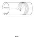
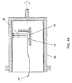
- Two common particular configurations of the second category are the so-called external-drum plotter, depicted schematically in Fig. 2, and the so-called internal-drum plotter, depicted schematically in Fig. 1.
- the external-drum plotter typically consists of a rotatable drum to whose external cylindrical surface the plate or film are attached, and an optical head that projects one or more light spots onto the sensitive surface of the attached plate or film.
- the drum rotates about its axis at a relatively high speed, while the optical head moves slowly in a path parallel to that axis.
- the film is usually held on to the surface of the drum by means of vacuum supplied through pores in that surface. In the case of plates either vacuum or a tensory clamping mechanism is used.
- the internal-drum plotter typically consists of a non-rotating member that features a concave cylindrical surface and an optical head inernal to that surface; the optical head includes a mirror or prism that is rotatable about the axis of the cylinder forming the surface.
- the film or plate are usually attached to the cylindrical surface by tangential force and/or by vacuum and the optical head projects a light spot onto its sensitive surface.
- the mirror or prism in the optical head rotates at relatively high speed, causing the light spot to scan the film tangentially.
- the optical head slowly moves in a path parallel to the axis of the cylinder.
- a major drawback of external drum plotters is the need for a strong centripetal force to keep the film or plate attached to the surface of the drum, providing the necessary bending moment, but mainly overcoming centrifugal inertia.
- the minimum required force is proportional to the mass ofthe plate and to the square ofthe rotational speed; it is thus particularly strong for fast rotating plotters with metal plates.
- two means are used to provide this attaching force -- tangential tension and vacuum Tangential tension applied alone must be very high if it is to provide the necessary centripetal force (in the radial direction).
- a major drawback of internal drum plotters is that the optics of the scanning head usually limit it to projecting a single spot of light onto the film or plate. Simultaneously projecting multiple spots, which is desirable for increasing the effective plotting rate at any given scanning speed, is possible relatively easily in all other plotter configurations; in internal drum plotters, however, such capability would require rather complex optics. Such complex optics, besides being inherently expensive, may burden the dynamic mechanical balancing of the rotating head, especially at very high speeds, which may, in turn, adversely affect attainable precision.
- the present invention successfully addresses the shortcomings of the presently known configurations by providing a graphic plotter that can economically record, or plot, images at relatively high rates on relatively thick films and plates.
- the present invention discloses a novel configuration of a graphic plotter consisting of a rotating drum and a non rotating optical assembly internal to the drum.
- the plotter of the present invention has a rotatable drum, to whose internal cylindrical surface a sheet of the plotting medium is attachable, so as to rotate therewith.
- Inside the drum there is an optical assembly, at least part of which is movable along a path parallel to the drum's axis, that projects one or more modulatable light spots onto the attached plotting medium.
- a relatively simple mechanism is used to attach the sheet to the drum, while centrifugal effects aid in making the sheet conform to the drum's internal surface. Provision is also made for loading and unloading the sheet through a slot in the wall of the drum.
- a plotter for recording an image on a sheet of light sensitive flexible medium comprising (a) a drum having a wall with cylindrical inner surface to which the sheet is attachable, the drum being rotatable about its geometric axis, and (b) an electro-optical system, projecting at least one modulatable light spot onto the inner surface of the drum wall.
- all or part of the electro-optical system is movable along a path parallel to the axis of the drum.
- the electro-optical system comprises a laser and a beam splitting acousto-optic modulator, or alternatively, a linear array of light modulators or of modulatable light sources.
- the wall of the drum has a slot therethrough, enabling insertion of the sheet into the drum for attachment to its inner surface.
- a mechanism for moving and holding the sheet inside the drum and there is optionally provided a loading mechanism for loading the sheet from a cassette.
- the outer surface of the drum is scannable -- either for plotting on a medium attached thereto or for reading an image attached thereto.
- the present invention is of a graphic plotter which can be employed to record electronically provided images on large format films and printing plates. Specifically, the present invention can be used to economically record, or plot, at relatively high rates on relatively thick films and plates.
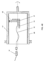
- Fig. 3 is a cross-sectional view of a preferred embodiment of the plotter according to the present invention.
- a drum 30 rotatable about a horizontal axis 33 .
- One end of the drum is closed and rigidly attached to a shaft 34 which is supported by bearing 36 and rotationally driven by a motor 38 .
- a rotational encoder (not shown), which continuously feeds control circuitry with information about the drum's angular position.
- the other end of the drum 30 is open and supported by a ring-shaped bearing 10 .
- the inside surface of the drum is machined to a precise cylindrical shape, whose axis is made to coincide with the axes of the two bearings.
- a rail 12 parallel to the axis of the drum Rail 12 extends to beyond the open end of the drum, where it is rigidly held by a support structure (not shown). Inside the drum the rail extends to near its closed end. It is appreciated that other configurations for rotationally supporting the drum are possible.
- a carriage 14 is slidable along rail 12 in a path parallel to the axis of the drum.
- the carriage is driven along this path by a lead screw 16 attached to an external motor (not shown).
- an external motor not shown
- any of a number of other means known in the art may be employed to move the carriage.
- To carriage 14 there is attached at least part of an electro-optical assembly 20 , which projects one or more light beams 21 in a radial direction onto the inner surface of the drum, where a plate or film 17 is attached in a manner to be explained herebelow.
- the light beams are focused to form small Spots on the inner (sensitive) surface of plate 17 , which are preferably arranged along a line parallel to the axis of the cylinder.
- the entire electro-optical assembly is mounted on carriage 14 and includes an array of modulatable light sources 31 , preferably light-emitting diodes (LEDs), which are focused onto the sensitive surface 17 by an objective lens 32 .
- the array of light sources which may include driving circuitry, is connected by electric wires 54 to outside circuitry (not shown).
- the LEDs 31 are mounted in a fixed position outside the drum; the light emitted from them is coupled into the input end of a bundle of optical fibers 15 , marked 'T', carried by the fibers to the output end, marked 'R', which is mounted on carriage 14 and projected by lens 32 onto the inner surface of the drum.
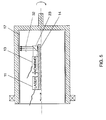
- the electro-optical assembly again entirely mounted on carriage 14 , consists of light source 11 , preferably a laser, projecting a beam of light, an acousto-optic multi-beam modulator/deflector (AOMBMD) 13 , possibly a fixed deflection mirror 23 and several lenses (not shown).
- AOMBMD 13 upon application of appropriate electrical voltage signals, acts to split the beam into several subbeams, deflecting them at various angles and modulating each one according to image information.
- a lens 32 acts to focus the subbbeams onto the surface ofplate 17 .
- a stationary light source 21 preferably a laser, and a collimating lens 22 are mounted outside the drum so as to project a collimated light beam parallel to the drum's axis into the drum.
- the rest of the electro-optical assembly, mounted on carriage 14 is essentially as described above for Fig. 5.
- the film or plate to be exposed 17 is attachable to the inner surface of the drum in any of a number of ways.
- the mechanically simplest way is to manually insert the plate into the drum through its open end and to attach one edge of the plate, preferably the leading edge, onto the drum's inner surface by means of a clamp, disposed lengthwise. During subsequent rotation of the drum, centrifugal inertia will act to push the entire plate onto the drum's surface. If the plate is too stiff to thus wholly adhere to the cylindrical surface, a vacuum system may be employed for the purpose.
- a slot 40 through the body of drum 30 over its entire length.
- the center plane of the slot is inclined at an angle to the radial plane.
- Slot 40 serves to feed a plate (or film) 17 into the drum, as well as to withdraw it from the drum.
- Plate (or film) 17 is usually fed from a cassette 44 into the slot with the aid offeed rollers 42 .
- One way of loading plates from a cassette is disclosed in U.S. patent application No. 08/501,839 by the assignee of the present application.
- main roller 46 is free to rotate with respect to the drum only while the latter is in its so-called home position, namely during loading or unloading.
- the rotation of roller 46 is frictionally imparted by means of a short drive roller 50 which is pressed against roller 46 and, in turn, rotated by a an external motor (not shown).
- main roller 46 is out of contact with drive roller 50 and is locked, so as to keep the plate in a fixed position with reject to the drum.
- a stop bar, or clamp, 48 attached to the drum, serves to stop the leading edge of the plate during loading and to press it toward the inner surface of the drum during plotting. Further details of the plate guiding mechanism are described, for example, in U.S. Patents 4,813,709 and 5,488,906 to the assignee of the present application.
- the plotted medium is assumed to be a printing plate, but other media and, in particular, photographic film sheets may be used in essentially the same manner. There are three stages of operation -- loading, plotting and unloading.
- the drum is locked in its home position.
- a fresh plate 17 is inserted through slot 40 in drum 2 , with its sensitive face directed inwards.
- the plate is gripped and pushed by main roller 46 so that its leading edge slides along the inner surface of the drum until it is stopped by stop bar 48 , at which instant the whole length of the plate is present inside the drum.
- the plate is pushed by main roller 46 somewhat more until the plate conforms to the inner drum's surface by tangential force.
- main roller 46 is locked and disengaged from drive roller 50 ; possibly also clamp 48 is engaged.
- the drum is unlocked from its home position and motor 8 is activated to rotate the drum and bring it up to operational speed.
- carriage 14 At the beginning of the plotting stage carriage 14 is in one extreme position of its travel range and the drum rotates at its operational speed. At this point optional calibration and zeroing operations may take place as is known in the art.
- the carriage With the optical assembly (or part thereof) mounted on it, is made to move slowly along its path; the motion may be continuous or in steps.
- Light beams 21 focused onto the sensitive surface ofplate 17 accordingly trace each either a helix or a series of parallel circles.
- the speed of the carriage, or the pitch of the step motion is controlled and adjusted so that the traces ofthe various spots exactly interlace. Meanwhile, signals are applied to multi-beam modulator 13 (Figs. 5 and 6) or to the LEDs 31 (Figs.
- Such modifications may include, for example, provisions for engaging mechanical and electrical connections to the drum while it is in the home position and disengaging them when the drum rotates. If vacuum is necessary for making the plate adhere to the inner surface, the relevant surface structure described in the '06 patent can be applied; central vacuum supply to the rotating drum may be similar to that of conventional external drum plotters.
- a plotter according to the present invention is an internal drum plotter (IDP), but with a rotatable drum as in an external drum plotter (EDP) and that it thus possesses advantages ofboth:
- EDP internal drum plotter
- EDP external drum plotter
- IDP internal drum plotter
- EDP external drum plotter
- a plotter according to the present invention has the additional advantage that centrifugal effects due to drum rotation actually aid in making the plate conform to a cylindrical surface.
- the invention thus uniquely enables very high plotting rates on any flexible medium by allowing both high scanning speed and multiple-beam exposure.
- a plotter according to the present invention lends itself to a number of practical configurations -- primarily by utilizing the external surface of the rotating drum.
- the outer surface may be configured to function as an external drum plotter, by providing means, such as clamps or vacuum, for attaching a medium onto it and an external electro-optical system for exposure.
- Such a configuration could be used, or instance, to expose a proofing medium simultaneously with exposing the plate inside the drum.
- the outer surface may be configured to function as an input scanner (i.e. image reader), by providing means for attaching an image carrying sheet onto it and an electro-optical reading head traveling along the drum.
- Such a configuration could be used, for instance, to effect direct plate preparation from an original or to directly produce color separations.
Landscapes
- Engineering & Computer Science (AREA)
- Multimedia (AREA)
- Signal Processing (AREA)
- Facsimile Scanning Arrangements (AREA)
- Exposure And Positioning Against Photoresist Photosensitive Materials (AREA)
Applications Claiming Priority (2)
| Application Number | Priority Date | Filing Date | Title |
|---|---|---|---|
| IL11880896A IL118808A0 (en) | 1996-07-07 | 1996-07-07 | Internal rotating drum plotter |
| IL11880896 | 1996-07-07 |
Publications (1)
| Publication Number | Publication Date |
|---|---|
| EP0818307A1 true EP0818307A1 (de) | 1998-01-14 |
Family
ID=11069054
Family Applications (1)
| Application Number | Title | Priority Date | Filing Date |
|---|---|---|---|
| EP97304823A Withdrawn EP0818307A1 (de) | 1996-07-07 | 1997-07-02 | Plotter mit drehbarer Trommel und innerer Aufzeichnung |
Country Status (2)
| Country | Link |
|---|---|
| EP (1) | EP0818307A1 (de) |
| IL (1) | IL118808A0 (de) |
Cited By (5)
| Publication number | Priority date | Publication date | Assignee | Title |
|---|---|---|---|---|
| EP0989735A1 (de) * | 1998-09-22 | 2000-03-29 | Fujifilm Electronic Imaging Limited | Bildabtastgerät |
| WO2001085586A1 (de) * | 2000-05-08 | 2001-11-15 | Kba-Giori S.A. | Einrichtung zum transport von bogenförmigen material |
| EP1021030A3 (de) * | 1999-01-12 | 2002-01-16 | Agfa Corporation | Innentrommelbebilderungssystem |
| EP1112842A3 (de) * | 1999-12-27 | 2002-11-06 | Fuji Photo Film Co., Ltd. | Innentrommel-Bildaufzeichnungsgerät |
| CN114630093A (zh) * | 2022-03-29 | 2022-06-14 | 征图新视(江苏)科技股份有限公司 | 滚筒式线阵投影光源 |
Citations (4)
| Publication number | Priority date | Publication date | Assignee | Title |
|---|---|---|---|---|
| JPH02296211A (ja) * | 1989-05-11 | 1990-12-06 | Canon Inc | ドラム走査型走査光学装置 |
| JPH037357A (ja) * | 1989-06-05 | 1991-01-14 | Asahi Chem Ind Co Ltd | 感熱記録装置 |
| EP0712723A2 (de) * | 1994-10-27 | 1996-05-22 | Bayer Corporation | Verfahren und Vorrichtung zur Mehrstrahlabtastung |
| EP0773661A1 (de) * | 1995-11-13 | 1997-05-14 | Agfa-Gevaert N.V. | Bildsatzgerät mit drehbarer Trommel |
-
1996
- 1996-07-07 IL IL11880896A patent/IL118808A0/xx unknown
-
1997
- 1997-07-02 EP EP97304823A patent/EP0818307A1/de not_active Withdrawn
Patent Citations (4)
| Publication number | Priority date | Publication date | Assignee | Title |
|---|---|---|---|---|
| JPH02296211A (ja) * | 1989-05-11 | 1990-12-06 | Canon Inc | ドラム走査型走査光学装置 |
| JPH037357A (ja) * | 1989-06-05 | 1991-01-14 | Asahi Chem Ind Co Ltd | 感熱記録装置 |
| EP0712723A2 (de) * | 1994-10-27 | 1996-05-22 | Bayer Corporation | Verfahren und Vorrichtung zur Mehrstrahlabtastung |
| EP0773661A1 (de) * | 1995-11-13 | 1997-05-14 | Agfa-Gevaert N.V. | Bildsatzgerät mit drehbarer Trommel |
Non-Patent Citations (2)
| Title |
|---|
| PATENT ABSTRACTS OF JAPAN vol. 015, no. 079 (P - 1170) 25 February 1991 (1991-02-25) * |
| PATENT ABSTRACTS OF JAPAN vol. 015, no. 113 (M - 1094) 18 March 1991 (1991-03-18) * |
Cited By (10)
| Publication number | Priority date | Publication date | Assignee | Title |
|---|---|---|---|---|
| EP0989735A1 (de) * | 1998-09-22 | 2000-03-29 | Fujifilm Electronic Imaging Limited | Bildabtastgerät |
| US6600549B1 (en) | 1998-09-22 | 2003-07-29 | Fujifilm Electronic Imaging Ltd. | Image scanning apparatus |
| EP1021030A3 (de) * | 1999-01-12 | 2002-01-16 | Agfa Corporation | Innentrommelbebilderungssystem |
| EP1112842A3 (de) * | 1999-12-27 | 2002-11-06 | Fuji Photo Film Co., Ltd. | Innentrommel-Bildaufzeichnungsgerät |
| US6509923B2 (en) | 1999-12-27 | 2003-01-21 | Fuji Photo Film Co., Ltd. | Inner drum type image recording device |
| WO2001085586A1 (de) * | 2000-05-08 | 2001-11-15 | Kba-Giori S.A. | Einrichtung zum transport von bogenförmigen material |
| RU2248317C2 (ru) * | 2000-05-08 | 2005-03-20 | Кба-Жиори С.А. | Устройство подачи листового материала |
| AU2001250232B2 (en) * | 2000-05-08 | 2005-07-14 | Kba-Giori S.A. | Device for conveying sheet-like material |
| CN114630093A (zh) * | 2022-03-29 | 2022-06-14 | 征图新视(江苏)科技股份有限公司 | 滚筒式线阵投影光源 |
| CN114630093B (zh) * | 2022-03-29 | 2022-12-30 | 征图新视(江苏)科技股份有限公司 | 滚筒式线阵投影光源 |
Also Published As
| Publication number | Publication date |
|---|---|
| IL118808A0 (en) | 1996-10-31 |
Similar Documents
| Publication | Publication Date | Title |
|---|---|---|
| US4070089A (en) | Two dimensional laser scanner with movable cylinder lens | |
| US5831757A (en) | Multiple cylinder deflection system | |
| US5701191A (en) | Optical scanner | |
| US4816923A (en) | Two dimensional light beam scanner used in radiation image information readout | |
| EP0822700B1 (de) | Strahlfehlerkorrektur unter Verwendung eines bewegbaren Korrekturelements | |
| US5598739A (en) | Self-propelled linear motion drive apparatus | |
| US5101223A (en) | Image-reproducing apparatus | |
| JPS62101165A (ja) | オプトエレクトロニクス式の走査ヘツド | |
| US4975714A (en) | Focusing mechanism for linescan imaging | |
| US6043865A (en) | Imagesetter | |
| US4511205A (en) | Scanning system wherein the scanning beam rotates and translates | |
| US5095320A (en) | Focusing mechanism for linescan imaging | |
| US5633672A (en) | Real-time calibration of processless writer | |
| JPS63261318A (ja) | 光偏向器ユニツト | |
| FI83567C (fi) | Foerfarande foer exponering av ljuskaensligt material medelst laserstraolar. | |
| JPS62178919A (ja) | 光ビ−ム走査装置 | |
| JPS5938724A (ja) | 光走査装置 | |
| JPS62246011A (ja) | 光ビ−ム走査装置 | |
| JPS6271378A (ja) | 光ビ−ム走査装置 | |
| JPH0457267B2 (de) | ||
| JPS6239815A (ja) | 光ビ−ム記録装置 | |
| EP0773661A1 (de) | Bildsatzgerät mit drehbarer Trommel | |
| JPS6285567A (ja) | 光ビ−ム走査装置 | |
| JPS6285569A (ja) | 光ビ−ム走査装置 | |
| JPH0458748B2 (de) |
Legal Events
| Date | Code | Title | Description |
|---|---|---|---|
| PUAI | Public reference made under article 153(3) epc to a published international application that has entered the european phase |
Free format text: ORIGINAL CODE: 0009012 |
|
| AK | Designated contracting states |
Kind code of ref document: A1 Designated state(s): BE DE FR GB |
|
| AKX | Designation fees paid |
Free format text: BE DE FR GB |
|
| RBV | Designated contracting states (corrected) |
Designated state(s): BE DE FR GB |
|
| RBV | Designated contracting states (corrected) |
Designated state(s): BE DE FR GB |
|
| STAA | Information on the status of an ep patent application or granted ep patent |
Free format text: STATUS: THE APPLICATION IS DEEMED TO BE WITHDRAWN |
|
| 18D | Application deemed to be withdrawn |
Effective date: 19980715 |