EP0818329A1 - Bohrverfahren für Speichenrad,Felge gebohrt nach dem Verfahren,Einsatz zur Ausrüstung der Felge und Rad inbesondere für ein Zweirad - Google Patents
Bohrverfahren für Speichenrad,Felge gebohrt nach dem Verfahren,Einsatz zur Ausrüstung der Felge und Rad inbesondere für ein Zweirad Download PDFInfo
- Publication number
- EP0818329A1 EP0818329A1 EP97111383A EP97111383A EP0818329A1 EP 0818329 A1 EP0818329 A1 EP 0818329A1 EP 97111383 A EP97111383 A EP 97111383A EP 97111383 A EP97111383 A EP 97111383A EP 0818329 A1 EP0818329 A1 EP 0818329A1
- Authority
- EP
- European Patent Office
- Prior art keywords
- rim
- chimney
- bridge
- insert
- wheel
- Prior art date
- Legal status (The legal status is an assumption and is not a legal conclusion. Google has not performed a legal analysis and makes no representation as to the accuracy of the status listed.)
- Withdrawn
Links
- 238000000034 method Methods 0.000 title claims description 14
- 238000005553 drilling Methods 0.000 title description 13
- 210000000078 claw Anatomy 0.000 claims abstract description 4
- 238000005520 cutting process Methods 0.000 claims description 6
- 238000004519 manufacturing process Methods 0.000 claims description 3
- 239000000463 material Substances 0.000 description 7
- 238000010079 rubber tapping Methods 0.000 description 3
- 230000008878 coupling Effects 0.000 description 2
- 238000010168 coupling process Methods 0.000 description 2
- 238000005859 coupling reaction Methods 0.000 description 2
- 229910000838 Al alloy Inorganic materials 0.000 description 1
- 235000009355 Dianthus caryophyllus Nutrition 0.000 description 1
- 240000006497 Dianthus caryophyllus Species 0.000 description 1
- 229910000842 Zamak Inorganic materials 0.000 description 1
- 229910045601 alloy Inorganic materials 0.000 description 1
- 239000000956 alloy Substances 0.000 description 1
- XAGFODPZIPBFFR-UHFFFAOYSA-N aluminium Chemical compound [Al] XAGFODPZIPBFFR-UHFFFAOYSA-N 0.000 description 1
- 229910052782 aluminium Inorganic materials 0.000 description 1
- 238000010276 construction Methods 0.000 description 1
- 238000009826 distribution Methods 0.000 description 1
- 238000009434 installation Methods 0.000 description 1
- 238000012423 maintenance Methods 0.000 description 1
- 238000004080 punching Methods 0.000 description 1
- 238000007665 sagging Methods 0.000 description 1
- 239000010935 stainless steel Substances 0.000 description 1
- 229910001220 stainless steel Inorganic materials 0.000 description 1
- 238000005728 strengthening Methods 0.000 description 1
- 238000003466 welding Methods 0.000 description 1
Images


Classifications
-
- B—PERFORMING OPERATIONS; TRANSPORTING
- B60—VEHICLES IN GENERAL
- B60B—VEHICLE WHEELS; CASTORS; AXLES FOR WHEELS OR CASTORS; INCREASING WHEEL ADHESION
- B60B1/00—Spoked wheels; Spokes thereof
- B60B1/02—Wheels with wire or other tension spokes
- B60B1/04—Attaching spokes to rim or hub
- B60B1/041—Attaching spokes to rim or hub of bicycle wheels
-
- B—PERFORMING OPERATIONS; TRANSPORTING
- B60—VEHICLES IN GENERAL
- B60B—VEHICLE WHEELS; CASTORS; AXLES FOR WHEELS OR CASTORS; INCREASING WHEEL ADHESION
- B60B1/00—Spoked wheels; Spokes thereof
- B60B1/02—Wheels with wire or other tension spokes
- B60B1/04—Attaching spokes to rim or hub
- B60B1/043—Attaching spokes to rim
- B60B1/044—Attaching spokes to rim by the use of spoke nipples
-
- B—PERFORMING OPERATIONS; TRANSPORTING
- B60—VEHICLES IN GENERAL
- B60B—VEHICLE WHEELS; CASTORS; AXLES FOR WHEELS OR CASTORS; INCREASING WHEEL ADHESION
- B60B21/00—Rims
- B60B21/02—Rims characterised by transverse section
- B60B21/025—Rims characterised by transverse section the transverse section being hollow
-
- B—PERFORMING OPERATIONS; TRANSPORTING
- B60—VEHICLES IN GENERAL
- B60B—VEHICLE WHEELS; CASTORS; AXLES FOR WHEELS OR CASTORS; INCREASING WHEEL ADHESION
- B60B21/00—Rims
- B60B21/02—Rims characterised by transverse section
- B60B21/026—Rims characterised by transverse section the shape of rim well
-
- B—PERFORMING OPERATIONS; TRANSPORTING
- B60—VEHICLES IN GENERAL
- B60B—VEHICLE WHEELS; CASTORS; AXLES FOR WHEELS OR CASTORS; INCREASING WHEEL ADHESION
- B60B21/00—Rims
- B60B21/06—Rims characterised by means for attaching spokes, i.e. spoke seats
- B60B21/062—Rims characterised by means for attaching spokes, i.e. spoke seats for bicycles
-
- B—PERFORMING OPERATIONS; TRANSPORTING
- B60—VEHICLES IN GENERAL
- B60B—VEHICLE WHEELS; CASTORS; AXLES FOR WHEELS OR CASTORS; INCREASING WHEEL ADHESION
- B60B21/00—Rims
- B60B21/06—Rims characterised by means for attaching spokes, i.e. spoke seats
- B60B21/064—Rims characterised by means for attaching spokes, i.e. spoke seats characterised by shape of spoke mounting holes, e.g. elliptical or triangular
Definitions
- the invention relates to a method for drilling a spoke rim, in particular a rim for cycle.
- the invention also relates to a rim pierced according to the process, an insert adapted to equip the rim thus pierced, a rim fitted with such inserts, as well as a wheel having a rim fitted with the inserts.
- a wheel in particular a bicycle, comprises a hub central connected by two plies of spokes to a circular rim.
- the rim is formed two annular bridges connected by two lateral flanks.
- the lateral flanks are extend outwards, so as to form a channel with the upper deck ring designed to receive a tire.
- the channel is a simple groove formed by a sagging of the upper deck inward.
- Spokes are connected to the rim by nuts screwed to the end of the spokes. These nuts also allow to adjust the spoke tension.
- the two rim bridges have holes distributed around the circumference of the rim. Bridge openings lower are intended to serve as a seat for the nut heads. Bridge openings upper, larger diameter, are located in line with the holes in the lower deck, and are provided to allow the fitting of the spoke nut from the outside.
- eyelets which pass through the holes in the lower deck.
- a monobloc eyelet is described in the Patent application EP 130 449.
- These eyelets also exist in two elements separate. These two-part eyelets are assembled by a crimp which secures the assembly to the periphery of an opening in the lower deck.
- One of two parts of these eyelets is a cup-shaped eyelet body whose lower part rests on the lower deck, and the upper part has a ledge which leans against the upper deck.
- the bottom of the eyelets is pierced for the passage of the nut body.
- the orifices constitute zones of weakness which weaken each of the two bridges.
- Another problem is that the eyelets impose certain constraints on the dimensions in section of the rim. Indeed, the eyelets are made the most often in stainless steel by stamping. The height of an eyelet is therefore limited, which imposes a determined maximum distance between the two bridges of the rim.
- the eyelet has in its upper part a collar by which the eyelet rests on the outer deck.
- This collar has a diameter or a dimension in width which is greater than the diameter of the body of the eyelet. From this done, it requires that the upper deck has a width at least equal to this width dimension of the collar.
- An object of the invention is to propose a method for drilling a rim and a rim obtained by the process which improves the mechanical resistance of the rim.
- Another object of the invention is to propose a drilling method and a rim which facilitate the fitting of inserts or eyelets.
- the method according to the invention for producing a rim pierced with orifices designed to receive connecting spokes with a hub, the rim having a box with an upper deck and a lower deck is characterized by the fact that the upper deck is pierced with a plurality of through holes drilled at by means of a drill by pushing back operating in the direction of the bridge lower, so as to create a discharge chimney at the level of each orifice of the upper deck, the length of which is greater than the thickness of the deck.
- the rim obtained by implementing the method of the invention is characterized in that at least the upper deck has a plurality through orifices delimited by a height discharge chimney greater than the thickness of the bridge.
- the wheel in particular cycle wheel, is characterized by the fact that it has a rim obtained by implementing the method of the invention.
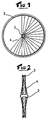
- Figure 1 is a general side view of a wheel.
- Figure 2 is a front view of the wheel of Figure 1.
- Figure 3 is a partial front view and in section through a section plane transverse of a rim in the rough.
- FIG. 4 illustrates the operation of drilling the rim according to a first mode of implementation of the invention.
- Figure 5 shows the result of the drilling operation.
- Figure 6 is a front view of an insert provided to equip the rim.
- FIG. 7 is a cross-sectional view of the insert of FIG. 6.
- Figure 8 is a sectional view of the rim at an insert.
- Figure 9 shows a front view of an insert according to a variant of implementation artwork.
- FIG. 10 is a cross-sectional view of the insert of FIG. 9.
- Figure 11 is a sectional view of the rim at an insert.
- Figure 1 shows a bicycle wheel which includes a circular rim 2 connected to a central hub 3 by spokes 4. Only part of the spokes is shown in this figure.
- the hub has means suitable for liaison with the frame.
- the rays are distributed in two symmetrical layers, each attached to one end of the hub 3.
- the wheel shown in Figures 1 and 2 is a front wheel.
- one of the spoke plies is offset towards the middle part of the hub, so that, on this side, the hub has a tip comprising the freewheel mechanism and used to support the gearbox. this is known to those skilled in the art.
- FIG. 3 shows in cross section and in partial view the rim 2 to raw.
- This rim has in known manner a box structure, with a lower deck 5, an upper deck 6 connected by side walls 7 and 8. These walls extend beyond the upper deck 6 by two wings 9 and 10 which form with the bridge 6 an annular channel intended to receive a tire and a air chamber.
- the rim shown in the figure is not, however, limiting for the invention, neither as regards the profile of the section, nor as regards the fitting a tire.
- the invention applies in fact as well to rims intended to be fitted with a tire only rims intended to be fitted of a hose.
- the rim such as that shown in FIG. 3 is produced at from a profiled bar made of aluminum alloy or another alloy lightweight, which is bent, then assembled end to end by means of a sleeve or by welding. In the raw state, the two bridges are continuous, non-pierced walls.
- a drilling operation is then carried out.
- This operation consists of drilling each of the upper and lower decks of a succession of orifices provided for the attachment of each of the spokes of the two layers.
- the upper deck holes and the lower deck are two by two in alignment with each other.
- the orifices of the upper deck are pierced at least in part by repression. That is, instead of using a traditional cutting drill which cuts the material and creates a chip, the hole is drilled here by discharge, by pushing the material in the direction of advancement of the drill, so that it creates a kind of fireplace.
- Such a chimney preserves a certain continuity of the material near the orifice.
- the structure of the bridge is little changed due to this continuity, much less in all cases than for traditional drilling. Yes although the resistance of the pierced rim is improved compared to a rim traditional.
- the chimney is also advantageous because it offers a useful height which is greater than the thickness of the bridge wall. This height can reach the double, or even triple, the wall thickness of the bridge. For a rim made in aluminum 6106, drilled with a 5.5 mm drill, we obtained a useful chimney height of around 5 millimeters on a 1.5 mm bridge thick. According to the invention, this significant useful height is used for ensure the guidance and attachment of an insert intended to serve as a seat for a spoke nut.
- Figure 4 illustrates the drilling operation.
- the rim is pierced by means of a double-stage drill 12.
- the forest is designed to pierce the rim from the outside to the inside.
- the lower stage 12a is a traditional small diameter cutting drill.
- This stage 12a is provided for drill a pilot hole in the upper deck 6, and then drill the bridge lower 5 of an orifice 14 provided for the passage of the spoke nut.
- the diameter of the stage 12a is provided as a function of the outside diameter of the spoke nut.
- the other stage 12b of larger diameter operates by pushing back. It presents a prismatic head 12c, the point of which is continuously extended by the stage of section 12a.
- the body of the stage 12b situated behind the head 12c has a cylindrical shape. Any other suitable form of the forest could also suit.
- Figure 5 shows the rim drilled by the drill 12.
- the lower bridge 5 has an orifice 14 pierced by the cutting stage 12a.
- the upper deck 6 presents him a chimney 15 whose wall is oriented towards the inside of the box of the rim. If necessary, the external face of the upper deck 6 is deburred around the chimney 15. This operation can be carried out with the drilling operation, or afterwards, in a separate operation.
- the drilling method described is not limiting, and we could drill both orifices, the orifice 14 and the orifice of the chimney 15 by two separate operations, using two separate drills. Under these conditions, the drill that pierces the bridge upper would no longer have a cutting stage, but only one repression.
- FIG. 6 represents a first embodiment of an insert 18 which is provided to equip the rim 2.
- Overall the insert has a body 19 of shape generally cylindrical, extended downwards by a centering collar 20.
- the insert 18 has a housing designed to receive the nut 21 of a department. Only the end 22 of the spoke is shown in Figure 8. So known, the spoke nut has a teardrop-shaped head, and it extended downwards by a nut body. Also known, the body nut has an area 23 with a square or other imprint suitable for coupling a clamping tool.
- the base of insert 18 is intended to serve as a seat for the head of the radius, and to be crossed by the nut body. Preferably, there is a slight angular clearance between the base of the insert and the nut, so that the nut is oriented itself in the extension of the spoke, when it is energized.
- the body 19 of the insert is designed to be introduced into the chimney 15. It has an outer diameter substantially equal to the inner diameter of the fireplace. At its base, the insert 18 has a centering collar 20. The collar is provided to enter hole 14 of the lower deck. To this end, it presents a external diameter substantially equal to the diameter of the orifice 14, and a height close to the thickness of bridge 5 at this level.
- the height of the body 19 is equal to or slightly less than the distance between the two bridges, so that when the insert is in abutment against the bridge lower, its upper part is guided in the chimney 15, as the represents figure 8.
- the insert present in its upper part a plurality of claws 20a, 20b, 20c, 20d which are intended to be planted in the wall of the chimney 15, thus ensuring the maintenance in position of the insert in the absence of radius.
- the claws are for example produced by tabs cut from the wall of the insert, and curved outwards.
- the free end of the tabs is oriented towards the upper part of the insert to authorize an engagement of insert it into the chimney and hold it in the opposite direction.
- the chimney 15 While strengthening the rigidity of the upper deck, the chimney 15 here facilitates the inserts because it guides the body of the insert until the centering neck is engaged in the orifice 14.
- the internal wall of the chimney offers a relatively large area for hanging of the insert. That is, it is possible to have dimension tolerances relatively large on the distance between the two bridges or on the height of the insert, without compromising the installation of the various elements.
- the insert is made of any suitable material, for example in a material known under the trade name "ZAMAC", or any other material appropriate.
- the base that serves as the seat for the spoke nut and the upper part of the body which guides and attaches the insert can also be produced in different materials.
- the upper deck can be defined with a width and any form.
- the lower deck could also have a shape different from that shown, for example, a "V" shaped section.
- the means for hooking the insert into the chimney could be different, and in particular be implemented by a punching operation or other during which the hooking means would be embedded in the chimney wall 15.
- FIGS 9 to 11 illustrate an alternative embodiment of the invention.
- the insert is not engaged and snapped into the chimney, but screwed.
- Rim 25 generally has a structure similar to rim former. In particular, it has an upper deck fitted with orifices drilled by discharge to create a chimney, and a lower deck pierced orifices in alignment with the chimneys.
- Figures 9 and 10 show an insert 26 which is of the same nature as insert 18, except that the upper part of its body has a thread 27 which is intended to cooperate with a tapping of the chimney 28.
- the thread 27 is intended to be screwed into a tapped chimney during a tapping. It can also be self-tapping, that is to say create its own own thread in the chimney 28.
- the insert 26 represented in the figures presents a hexagonal imprint 29 intended for ensure coupling with a suitable clamping tool, in particular a wrench ALLEN type. Of course, any other suitable means is suitable.
- a suitable clamping tool in particular a wrench ALLEN type.
- any suitable means is suitable.
- the insert in abutment abuts against the lower bridge 31.
- any suitable means such as bonding may be used to avoid loosening accidental.
- the insert has a neck at its bottom centering 30.
- this neck is not essential, and the insert could rest directly on the lower deck.
- the chimneys 28 reinforce the structure of the upper deck because they preserve the continuity of the structure of the bridge near the orifices.
- the advantage of this construction method is that the insert establishes a mechanical connection between the two bridges of the same like a traditional double eyelet. Indeed, the insert transmits the voltage from radius at both the lower deck 31 and the upper deck 32, and where appropriate the variation of this voltage.
- the thread provides guidance which facilitates the fitting the insert.
Landscapes
- Engineering & Computer Science (AREA)
- Mechanical Engineering (AREA)
- Connection Of Plates (AREA)
Applications Claiming Priority (2)
| Application Number | Priority Date | Filing Date | Title |
|---|---|---|---|
| FR9609048A FR2750914B1 (fr) | 1996-07-12 | 1996-07-12 | Procede de percage d'une jante a rayon, jante percee selon le procede, insert adapte pour equiper la jante, et roue notamment de cycle |
| FR9609048 | 1996-07-12 |
Publications (1)
| Publication Number | Publication Date |
|---|---|
| EP0818329A1 true EP0818329A1 (de) | 1998-01-14 |
Family
ID=9494220
Family Applications (1)
| Application Number | Title | Priority Date | Filing Date |
|---|---|---|---|
| EP97111383A Withdrawn EP0818329A1 (de) | 1996-07-12 | 1997-07-05 | Bohrverfahren für Speichenrad,Felge gebohrt nach dem Verfahren,Einsatz zur Ausrüstung der Felge und Rad inbesondere für ein Zweirad |
Country Status (2)
| Country | Link |
|---|---|
| EP (1) | EP0818329A1 (de) |
| FR (1) | FR2750914B1 (de) |
Cited By (5)
| Publication number | Priority date | Publication date | Assignee | Title |
|---|---|---|---|---|
| FR2792250A1 (fr) * | 1999-04-16 | 2000-10-20 | Mavic Sa | Roue de bicyclette a rayons |
| FR2793444A1 (fr) * | 1999-05-12 | 2000-11-17 | Mavic Sa | Dispositif d'accrochage d'un rayon a la jante d'une roue de bicyclette |
| EP1209006A1 (de) * | 2000-11-22 | 2002-05-29 | COSTRUZIONI MECCANICHE RHO S.p.A. | Speichenrad und dazugehörende Nippel zum Festsetzen der Speichen |
| EP1502768A3 (de) * | 2003-08-01 | 2005-09-07 | Shimano Inc. | Fahrradfelge |
| CN104889232A (zh) * | 2015-04-24 | 2015-09-09 | 浙江金固股份有限公司 | 一种钢制车轮轮辐螺母座孔制作方法 |
Families Citing this family (1)
| Publication number | Priority date | Publication date | Assignee | Title |
|---|---|---|---|---|
| FR2777496B1 (fr) | 1998-04-17 | 2000-08-04 | Sunkiss Aeronautique | Procede d'obtention, reparation ou reconstruction d'un objet avec une piece ou materiau composite |
Citations (5)
| Publication number | Priority date | Publication date | Assignee | Title |
|---|---|---|---|---|
| FR1029764A (fr) * | 1950-12-16 | 1953-06-05 | Perfectionnements aux jantes pour cycles et autres | |
| EP0130449A2 (de) * | 1983-06-24 | 1985-01-09 | Campagnolo S.p.A. | Schräge Buchsen für Fahrradfelgen und Felgen die damit ausgestattet sind |
| WO1996011075A1 (en) * | 1994-10-05 | 1996-04-18 | Holland Mechanics B.V. | Method and apparatus for making nipple holes in a double-walled hollow rim of a spoke wheel |
| EP0714792A1 (de) * | 1994-11-30 | 1996-06-05 | Mavic S.A. | Fahrradfelge und Rad mit derartiger Felge |
| EP0714791A1 (de) * | 1994-12-02 | 1996-06-05 | Mavic S.A. | Fahrradfelge, ausgerüstet mit Führungsmitteln für Schrauben |
-
1996
- 1996-07-12 FR FR9609048A patent/FR2750914B1/fr not_active Expired - Lifetime
-
1997
- 1997-07-05 EP EP97111383A patent/EP0818329A1/de not_active Withdrawn
Patent Citations (5)
| Publication number | Priority date | Publication date | Assignee | Title |
|---|---|---|---|---|
| FR1029764A (fr) * | 1950-12-16 | 1953-06-05 | Perfectionnements aux jantes pour cycles et autres | |
| EP0130449A2 (de) * | 1983-06-24 | 1985-01-09 | Campagnolo S.p.A. | Schräge Buchsen für Fahrradfelgen und Felgen die damit ausgestattet sind |
| WO1996011075A1 (en) * | 1994-10-05 | 1996-04-18 | Holland Mechanics B.V. | Method and apparatus for making nipple holes in a double-walled hollow rim of a spoke wheel |
| EP0714792A1 (de) * | 1994-11-30 | 1996-06-05 | Mavic S.A. | Fahrradfelge und Rad mit derartiger Felge |
| EP0714791A1 (de) * | 1994-12-02 | 1996-06-05 | Mavic S.A. | Fahrradfelge, ausgerüstet mit Führungsmitteln für Schrauben |
Cited By (5)
| Publication number | Priority date | Publication date | Assignee | Title |
|---|---|---|---|---|
| FR2792250A1 (fr) * | 1999-04-16 | 2000-10-20 | Mavic Sa | Roue de bicyclette a rayons |
| FR2793444A1 (fr) * | 1999-05-12 | 2000-11-17 | Mavic Sa | Dispositif d'accrochage d'un rayon a la jante d'une roue de bicyclette |
| EP1209006A1 (de) * | 2000-11-22 | 2002-05-29 | COSTRUZIONI MECCANICHE RHO S.p.A. | Speichenrad und dazugehörende Nippel zum Festsetzen der Speichen |
| EP1502768A3 (de) * | 2003-08-01 | 2005-09-07 | Shimano Inc. | Fahrradfelge |
| CN104889232A (zh) * | 2015-04-24 | 2015-09-09 | 浙江金固股份有限公司 | 一种钢制车轮轮辐螺母座孔制作方法 |
Also Published As
| Publication number | Publication date |
|---|---|
| FR2750914B1 (fr) | 1998-10-09 |
| FR2750914A1 (fr) | 1998-01-16 |
Similar Documents
| Publication | Publication Date | Title |
|---|---|---|
| EP1531062B1 (de) | Bohrungsverfahren für Speichenrad, Felge gebohrt nach dem Verfahren, Einsatz zur Ausrüstung der Felge und Rad insbesondere für ein Zweirad | |
| EP0893280B1 (de) | Fahrradnabe für die Montierung eines schlauchlosen Reifens und Fahrradrad | |
| EP1084868B1 (de) | Fahrradfelge und Rad mit solcher Felge | |
| EP0714792B1 (de) | Fahrradfelge und Rad mit derartiger Felge | |
| FR2810582A1 (fr) | Dispositif d'accrochage d'un rayon a la jante d'une roue de bicyclette | |
| US7448696B2 (en) | Rim and spoke connection for a bicycle wheel | |
| EP0579525B1 (de) | Verfahren zur Herstellung einer Fahrradfelge und nach diesem Verfahren hergestellte Felge | |
| EP1206357B1 (de) | Felge und unterstützungsvorrichtung | |
| FR2802853A1 (fr) | Moyeu d'une roue a rayons notamment d'une roue de bicyclette | |
| FR2806663A1 (fr) | Jante pour roue de bicyclette a rayons | |
| EP3825594A1 (de) | Schlauchklemme | |
| FR2951668A1 (fr) | Jante de roue a rayons, ensemble monte l'incorporant et son procede d'assemblage | |
| EP0714791B1 (de) | Fahrradfelge, ausgerüstet mit Führungsmitteln für Schrauben | |
| EP0818329A1 (de) | Bohrverfahren für Speichenrad,Felge gebohrt nach dem Verfahren,Einsatz zur Ausrüstung der Felge und Rad inbesondere für ein Zweirad | |
| FR2882689A1 (fr) | Moyeu d'une roue de cycle a rayons en traction et roue de cycle a rayons equipee d'un tel moyeu | |
| WO2002020338A2 (fr) | Dispositif d'accrochage d'un rayon a la jante d'une roue de bicyclette | |
| FR2765150A1 (fr) | Jante pour roue de bicyclette | |
| EP0893285A1 (de) | Ventil und Felge eines Fahrradrades für schlauchlose Reifen | |
| FR2808734A1 (fr) | Dispositif de roulage a plat pour vehicule automobile | |
| FR2792250A1 (fr) | Roue de bicyclette a rayons | |
| FR2887493A1 (fr) | Jante pour une roue a rayons en traction et roue comprenant une telle jante | |
| FR2502551A1 (fr) | Jante de roue | |
| EP1551648B1 (de) | Aus zwei montierten konstruktionen bestehende radfelge | |
| FR2825319A1 (fr) | Procede de construction d'une roue a rayons sous tension et roue a rayons sous tension destinee a un vehicule a deux roues | |
| FR2793444A1 (fr) | Dispositif d'accrochage d'un rayon a la jante d'une roue de bicyclette |
Legal Events
| Date | Code | Title | Description |
|---|---|---|---|
| PUAI | Public reference made under article 153(3) epc to a published international application that has entered the european phase |
Free format text: ORIGINAL CODE: 0009012 |
|
| AK | Designated contracting states |
Kind code of ref document: A1 Designated state(s): BE CH DE ES GB IT LI NL PT |
|
| 17P | Request for examination filed |
Effective date: 19980326 |
|
| AKX | Designation fees paid |
Free format text: BE CH DE ES GB IT LI NL PT |
|
| RBV | Designated contracting states (corrected) |
Designated state(s): BE CH DE ES GB IT LI NL PT |
|
| 17Q | First examination report despatched |
Effective date: 20001012 |
|
| RTI1 | Title (correction) |
Free format text: PROCESS FOR DRILLING A SPOKE WHEEL RIM, RIM DRILLED ACCORDING THE PROCESS AND WHEEL WITH RIM, PARTICULARLY FOR CYCLE |
|
| GRAG | Despatch of communication of intention to grant |
Free format text: ORIGINAL CODE: EPIDOS AGRA |
|
| GRAG | Despatch of communication of intention to grant |
Free format text: ORIGINAL CODE: EPIDOS AGRA |
|
| GRAH | Despatch of communication of intention to grant a patent |
Free format text: ORIGINAL CODE: EPIDOS IGRA |
|
| GRAH | Despatch of communication of intention to grant a patent |
Free format text: ORIGINAL CODE: EPIDOS IGRA |
|
| STAA | Information on the status of an ep patent application or granted ep patent |
Free format text: STATUS: THE APPLICATION IS DEEMED TO BE WITHDRAWN |
|
| 18D | Application deemed to be withdrawn |
Effective date: 20020430 |