EP0818341A2 - Transmission électronique pour entraínement à quatre roues motrices - Google Patents
Transmission électronique pour entraínement à quatre roues motrices Download PDFInfo
- Publication number
- EP0818341A2 EP0818341A2 EP97202068A EP97202068A EP0818341A2 EP 0818341 A2 EP0818341 A2 EP 0818341A2 EP 97202068 A EP97202068 A EP 97202068A EP 97202068 A EP97202068 A EP 97202068A EP 0818341 A2 EP0818341 A2 EP 0818341A2
- Authority
- EP
- European Patent Office
- Prior art keywords
- drive
- coupling
- teeth
- transmission
- wheel drive
- Prior art date
- Legal status (The legal status is an assumption and is not a legal conclusion. Google has not performed a legal analysis and makes no representation as to the accuracy of the status listed.)
- Granted
Links
- 230000005540 biological transmission Effects 0.000 title claims abstract description 68
- 230000008878 coupling Effects 0.000 claims abstract description 93
- 238000010168 coupling process Methods 0.000 claims abstract description 93
- 238000005859 coupling reaction Methods 0.000 claims abstract description 93
- 230000033001 locomotion Effects 0.000 claims description 29
- 238000000034 method Methods 0.000 claims description 13
- 230000004044 response Effects 0.000 claims description 6
- 238000006073 displacement reaction Methods 0.000 claims description 4
- 238000012544 monitoring process Methods 0.000 claims description 3
- 238000012545 processing Methods 0.000 description 4
- 230000008859 change Effects 0.000 description 3
- 230000004048 modification Effects 0.000 description 3
- 238000012986 modification Methods 0.000 description 3
- 230000009471 action Effects 0.000 description 2
- 230000008901 benefit Effects 0.000 description 2
- 230000001419 dependent effect Effects 0.000 description 2
- 238000005259 measurement Methods 0.000 description 2
- 238000010276 construction Methods 0.000 description 1
- 238000013461 design Methods 0.000 description 1
- 238000001514 detection method Methods 0.000 description 1
- 230000000694 effects Effects 0.000 description 1
- 239000012530 fluid Substances 0.000 description 1
- 230000001939 inductive effect Effects 0.000 description 1
- 230000000717 retained effect Effects 0.000 description 1
- 230000007704 transition Effects 0.000 description 1
Images



Classifications
-
- B—PERFORMING OPERATIONS; TRANSPORTING
- B60—VEHICLES IN GENERAL
- B60K—ARRANGEMENT OR MOUNTING OF PROPULSION UNITS OR OF TRANSMISSIONS IN VEHICLES; ARRANGEMENT OR MOUNTING OF PLURAL DIVERSE PRIME-MOVERS IN VEHICLES; AUXILIARY DRIVES FOR VEHICLES; INSTRUMENTATION OR DASHBOARDS FOR VEHICLES; ARRANGEMENTS IN CONNECTION WITH COOLING, AIR INTAKE, GAS EXHAUST OR FUEL SUPPLY OF PROPULSION UNITS IN VEHICLES
- B60K23/00—Arrangement or mounting of control devices for vehicle transmissions, or parts thereof, not otherwise provided for
- B60K23/08—Arrangement or mounting of control devices for vehicle transmissions, or parts thereof, not otherwise provided for for changing number of driven wheels, for switching from driving one axle to driving two or more axles
-
- B—PERFORMING OPERATIONS; TRANSPORTING
- B60—VEHICLES IN GENERAL
- B60K—ARRANGEMENT OR MOUNTING OF PROPULSION UNITS OR OF TRANSMISSIONS IN VEHICLES; ARRANGEMENT OR MOUNTING OF PLURAL DIVERSE PRIME-MOVERS IN VEHICLES; AUXILIARY DRIVES FOR VEHICLES; INSTRUMENTATION OR DASHBOARDS FOR VEHICLES; ARRANGEMENTS IN CONNECTION WITH COOLING, AIR INTAKE, GAS EXHAUST OR FUEL SUPPLY OF PROPULSION UNITS IN VEHICLES
- B60K17/00—Arrangement or mounting of transmissions in vehicles
- B60K17/34—Arrangement or mounting of transmissions in vehicles for driving both front and rear wheels, e.g. four wheel drive vehicles
-
- B—PERFORMING OPERATIONS; TRANSPORTING
- B60—VEHICLES IN GENERAL
- B60W—CONJOINT CONTROL OF VEHICLE SUB-UNITS OF DIFFERENT TYPE OR DIFFERENT FUNCTION; CONTROL SYSTEMS SPECIALLY ADAPTED FOR HYBRID VEHICLES; ROAD VEHICLE DRIVE CONTROL SYSTEMS FOR PURPOSES NOT RELATED TO THE CONTROL OF A PARTICULAR SUB-UNIT
- B60W2520/00—Input parameters relating to overall vehicle dynamics
- B60W2520/26—Wheel slip
- B60W2520/263—Slip values between front and rear axle
-
- B—PERFORMING OPERATIONS; TRANSPORTING
- B60—VEHICLES IN GENERAL
- B60W—CONJOINT CONTROL OF VEHICLE SUB-UNITS OF DIFFERENT TYPE OR DIFFERENT FUNCTION; CONTROL SYSTEMS SPECIALLY ADAPTED FOR HYBRID VEHICLES; ROAD VEHICLE DRIVE CONTROL SYSTEMS FOR PURPOSES NOT RELATED TO THE CONTROL OF A PARTICULAR SUB-UNIT
- B60W2540/00—Input parameters relating to occupants
- B60W2540/18—Steering angle
-
- B—PERFORMING OPERATIONS; TRANSPORTING
- B60—VEHICLES IN GENERAL
- B60W—CONJOINT CONTROL OF VEHICLE SUB-UNITS OF DIFFERENT TYPE OR DIFFERENT FUNCTION; CONTROL SYSTEMS SPECIALLY ADAPTED FOR HYBRID VEHICLES; ROAD VEHICLE DRIVE CONTROL SYSTEMS FOR PURPOSES NOT RELATED TO THE CONTROL OF A PARTICULAR SUB-UNIT
- B60W2552/00—Input parameters relating to infrastructure
- B60W2552/15—Road slope, i.e. the inclination of a road segment in the longitudinal direction
Definitions
- two-wheel drive is to be preferred to four-wheel drive because even when the front axle differential is not locked, the front wheel on the outside of the bend tends to travel up to 20% faster than the rear wheels so that, if four-wheel drive would be engaged, this front wheel would slip, again causing considerable wear on the tyre.
- a tractor it is desirable in a tractor to be able to select between two-wheel and four-wheel drive in dependence upon the road surface on which the tractor is driven.
- the tractor should have four-wheel drive engaged only under poor road adhesion conditions when the rear wheels slip with respect to the ground.
- a transmission for a motor vehicle having selectable four-wheel drive comprising a coupling for selectively applying torque to the front wheels of the vehicle to switch between two-wheel drive and four-wheel drive; said coupling comprising a drive member rotatable with the rear wheels and a driven member rotatable with the front wheels, the drive and driven members being movable axially relative to one another.
- the drive and driven members of the coupling are engaged with one another when drive is to be transmitted through the coupling and are totally disengaged from one another by being moved axially when two-wheel drive is engaged.
- the invention offers the advantage that it does not rely on surfaces that slip relative to one another when two-wheel drive is engaged, so that no component is subjected to unnecessary wear.
- the direction of torque transmission may be sensed in a variety of ways, for example by measuring the deflection along the length of a torsion tube included in the torque transmission path. It is preferred however for the teeth on the drive and driven member of the coupling to engage one another with lost motion and to determine the direction of torque transmission through the coupling by monitoring the relative angular displacement of the drive and driven members.
- a control system for a transmission of a motor vehicle having selectable four-wheel drive for switching between two-wheel drive and four-wheel drive in dependence upon slipping of the driven wheels.
- the control system is characterized in that it comprises :
- the coupling is a lost motion or a resilient coupling the ends of which may rotate relative to one another in dependence upon the direction of torque transmission through the coupling and the means for determining the direction of torque transmission through the coupling comprises means for comparing the phase of the first and second electrical signals.
- a transmission for a motor vehicle having selectable four-wheel drive comprising a coupling for selectively applying torque to the front wheels of the vehicle to switch between two-wheel drive and four-wheel drive; said coupling comprising a drive member rotatable with the rear wheels and a driven member rotatable with the front wheels, the drive and driven members being movable axially relative to one another.
- Figure 1 shows part of a transmission for a tractor.
- the transmission is neither shown complete nor in detail as its construction is in itself well known and an understanding of its operation is not fundamental to the present invention. It suffices to understand that the transmission has an output shaft 10 that leads to the rear wheels and is driven with variable drive ratio by the engine of the tractor.
- the transmission also has a second output shaft 12 which drives the front wheels, the two shafts 10 and 12 being selectively coupled to one another by a coupling which is generally designated 100 and which will now be described in greater detail.
- a gear 14 is mounted by means of a keyway 16 for permanent rotation with the shaft 10 and meshes with a gear 18 that is freely rotatable about the shaft 12.
- the gear 18 has two axially projecting dog teeth 20 which are selectively engageable with two axially projecting teeth 22 on a collar 24 fast in rotation with the shaft 12.
- the collar 24 is slidably mounted on a sleeve 26 and is keyed for rotation with the latter by splines 34.
- the sleeve 26 is keyed to the shaft 12 by splines 40.
- the sleeve 26 is captured between a shoulder on the shaft 12 and a circlip 42 so that it cannot move axially relative to the shaft 12.
- the collar 24 is slidable axially over the sleeve 26 and between these two elements there is defined a sealed annular working chamber 36 which communicates through radial apertures (not shown) in the sleeve 26, radial bores (not shown) in the shaft 12 and an axial blind bore 38 in the shaft 12 with a supply conduit 44 which is selectively connected to a pressure supply or to a drain in order to disengage or engage the teeth 20, 22 of the coupling 100, respectively.
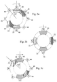
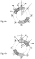
- the direction in which this lost motion is taken up depends on the direction through which torque is transmitted through the coupling.
- the coupling is represented as rotating in the clockwise direction, as indicated by the arrow, which corresponds to the forward drive of the tractor. If the gear 18 tries to turn faster than the collar 24 then the teeth 20 of the gear 18 will drive the teeth 22 of the collar 24 and the lost motion is taken up in one direction, as represented in Figure 3a. On the other hand, if the collar 24 tries to turn more rapidly than the gear 18 then the teeth 22 will drive the teeth 20 and the lost motion is taken up in the opposite direction, as represented in Figure 3c.
- the relative angular position or phase of the gear 18 and the collar 24 will therefore depend on the direction of torque transmission through the coupling 100.
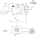
- the signals from the sensors 50 and 52 are applied to a control circuit 54 that determines from these signals the road conditions on the basis of the criteria described above.
- the output of the control circuit 54 acts on a relay having a contact 56 that controls a three port, two position electro-hydraulic valve 70.
- the relay contact 56 is open and the valve 70 connects the conduit 44 leading to the working chamber 36 of the coupling 100 to the output line 68 of a pressure regulator 66.
- Fluid under pressure is supplied to the regulator 66 by a pump 64 which is connected to a reservoir 60 through an input line 62.
- the pressurised chamber 36 causes the drive to the front wheels to be disengaged in the manner earlier described.
- the control circuit 54 closes the relay contact 56.
- the valve 70 is now energised into its second position in which the line 68 from the regulator 66 is blanked off and the conduit 44 is connected through a return line 74 to the reservoir 60.
- the spring 28 now compresses the working chamber 36 and moves the collar 24 to the left (when considering Figure 1) thereby causing the dog teeth 20 and 22 to mesh with one another.
- the shafts 10 and 12 can rotate at different speeds.
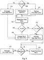
- the front wheels driven by the ground, will drive the shaft 12 at a higher rotational speed than the speed of the shaft 10 driving the rear wheels. Therefore the A signal will have a higher frequency than the P signal.
- the A signal which is related to the speed of the tractor along the ground, will have a lower frequency than the P signal.
Landscapes
- Engineering & Computer Science (AREA)
- Chemical & Material Sciences (AREA)
- Combustion & Propulsion (AREA)
- Transportation (AREA)
- Mechanical Engineering (AREA)
- Arrangement And Driving Of Transmission Devices (AREA)
- Arrangement And Mounting Of Devices That Control Transmission Of Motive Force (AREA)
Priority Applications (2)
| Application Number | Priority Date | Filing Date | Title |
|---|---|---|---|
| EP04103103A EP1464531B1 (fr) | 1996-07-12 | 1997-07-04 | Transmission électronique pour entraînement à quatre roues motrices |
| EP04103102A EP1464530B1 (fr) | 1996-07-12 | 1997-07-04 | Transmission électronique pour entraînement à quatre roues motrices |
Applications Claiming Priority (2)
| Application Number | Priority Date | Filing Date | Title |
|---|---|---|---|
| IT96TO000599A IT1286172B1 (it) | 1996-07-12 | 1996-07-12 | Trasmissione elettronica per un veicolo a quattro ruote motrici. |
| ITTO960599 | 1996-07-12 |
Related Child Applications (2)
| Application Number | Title | Priority Date | Filing Date |
|---|---|---|---|
| EP04103102A Division EP1464530B1 (fr) | 1996-07-12 | 1997-07-04 | Transmission électronique pour entraînement à quatre roues motrices |
| EP04103103A Division EP1464531B1 (fr) | 1996-07-12 | 1997-07-04 | Transmission électronique pour entraînement à quatre roues motrices |
Publications (3)
| Publication Number | Publication Date |
|---|---|
| EP0818341A2 true EP0818341A2 (fr) | 1998-01-14 |
| EP0818341A3 EP0818341A3 (fr) | 1999-04-21 |
| EP0818341B1 EP0818341B1 (fr) | 2004-09-15 |
Family
ID=11414778
Family Applications (3)
| Application Number | Title | Priority Date | Filing Date |
|---|---|---|---|
| EP04103103A Expired - Lifetime EP1464531B1 (fr) | 1996-07-12 | 1997-07-04 | Transmission électronique pour entraînement à quatre roues motrices |
| EP04103102A Expired - Lifetime EP1464530B1 (fr) | 1996-07-12 | 1997-07-04 | Transmission électronique pour entraînement à quatre roues motrices |
| EP97202068A Expired - Lifetime EP0818341B1 (fr) | 1996-07-12 | 1997-07-04 | Transmission électronique pour entraínement à quatre roues motrices |
Family Applications Before (2)
| Application Number | Title | Priority Date | Filing Date |
|---|---|---|---|
| EP04103103A Expired - Lifetime EP1464531B1 (fr) | 1996-07-12 | 1997-07-04 | Transmission électronique pour entraînement à quatre roues motrices |
| EP04103102A Expired - Lifetime EP1464530B1 (fr) | 1996-07-12 | 1997-07-04 | Transmission électronique pour entraînement à quatre roues motrices |
Country Status (4)
| Country | Link |
|---|---|
| US (1) | US6131686A (fr) |
| EP (3) | EP1464531B1 (fr) |
| DE (3) | DE69738552T2 (fr) |
| IT (1) | IT1286172B1 (fr) |
Cited By (3)
| Publication number | Priority date | Publication date | Assignee | Title |
|---|---|---|---|---|
| EP1112887A3 (fr) * | 1999-12-28 | 2003-01-15 | Kanzaki Kokyukoki Mfg. Co., Ltd. | Embrayage pour traction avant pour tracteurs |
| EP1625965A3 (fr) * | 2004-08-12 | 2006-06-07 | Kanzaki Kokyukoki Mfg. Co., Ltd. | Boîte de transfert d'un véhicule à roues motrices multiples |
| WO2013144346A1 (fr) * | 2012-03-30 | 2013-10-03 | Jaguar Land Rover Limited | Procédé, système et dispositif de régulation antipatinage de véhicule et véhicule équipé d'un tel système |
Families Citing this family (15)
| Publication number | Priority date | Publication date | Assignee | Title |
|---|---|---|---|---|
| GB0217309D0 (en) * | 2002-07-25 | 2002-09-04 | Lucas Industries Ltd | Drive disconnect device |
| US6932033B2 (en) * | 2003-07-10 | 2005-08-23 | Borgwarner Inc. | System and method for improving VCT closed-loop response at low cam torque frequency |
| US7419041B2 (en) * | 2004-08-19 | 2008-09-02 | Gm Global Technology Operations, Inc. | Main shaft dog clutch and method |
| US20080047572A1 (en) * | 2006-08-22 | 2008-02-28 | Hui Suk Park | Wig arrangement with primary wig and detachable wig extension |
| DE102009026706A1 (de) | 2009-06-04 | 2010-12-09 | Zf Friedrichshafen Ag | Lageranordnung für eine Welle |
| DE102009026707B4 (de) | 2009-06-04 | 2022-01-27 | Zf Friedrichshafen Ag | Anordnung mit zumindest einer Klauenkupplung |
| DE102009026708A1 (de) | 2009-06-04 | 2010-12-09 | Zf Friedrichshafen Ag | Anordnung mit zumindest einer Klauenkupplung |
| DE102009026710A1 (de) * | 2009-06-04 | 2010-12-09 | Zf Friedrichshafen Ag | Anordnung mit zumindest einer Klauenkupplung |
| US20120095659A1 (en) * | 2010-10-18 | 2012-04-19 | Ford Global Technologies, Llc | Automatic Control of Driveline States |
| US10166865B2 (en) | 2010-10-18 | 2019-01-01 | Ford Global Technologies, Llc | Automatic control of driveline states |
| DE102011105990B4 (de) * | 2011-06-30 | 2021-03-18 | Schaeffler Technologies AG & Co. KG | Verfahren zur Steuerung eines Antriebsstrangs eines Kraftfahrzeugs |
| DE102014016451B3 (de) * | 2014-11-06 | 2016-03-24 | Audi Ag | Verfahren zum Betreiben eines Mehrachsantriebsstrangs für ein Kraftfahrzeug sowie entsprechender Mehrachsantriebsstrang |
| JP6199912B2 (ja) * | 2015-01-13 | 2017-09-20 | トヨタ自動車株式会社 | 噛み合い式係合機構の制御装置 |
| DE102015212897B4 (de) * | 2015-07-09 | 2024-11-14 | Deere & Company | Einrichtung zum Betreiben eines allradgetriebenen landwirtschaftlichen Nutzfahrzeugs |
| KR20220170294A (ko) * | 2021-06-22 | 2022-12-29 | 현대자동차주식회사 | 4륜 차량의 디스커넥터 제어를 통한 회생 제동 장치 및 방법 |
Citations (1)
| Publication number | Priority date | Publication date | Assignee | Title |
|---|---|---|---|---|
| EP0432549A1 (fr) | 1989-12-13 | 1991-06-19 | FIATGEOTECH - TECNOLOGIE PER LA TERRA S.p.A. | Dispositif pour l'engagement d'une transmission à quatre roues motrices dans un véhicule |
Family Cites Families (12)
| Publication number | Priority date | Publication date | Assignee | Title |
|---|---|---|---|---|
| JPS6064036A (ja) * | 1983-09-20 | 1985-04-12 | Fuji Heavy Ind Ltd | 4輪駆動車の切換制御装置 |
| DE3621225C1 (de) * | 1986-06-25 | 1987-05-27 | Daimler Benz Ag | Steuereinrichtung fuer die zeitweise Umschaltung eines Fahrzeugantriebes von einachsigem Antrieb ueber eine permanent angetriebene Fahrzeugachse auf zweiachsigen Antrieb |
| US4848508A (en) * | 1987-10-05 | 1989-07-18 | Borg-Warner Automotive, Inc. | Method and apparatus for controlling wheel slip in a full-time four wheel drive vehicle |
| AT398948B (de) * | 1989-10-25 | 1995-02-27 | Steyr Daimler Puch Ag | Verteilergetriebe für ein kraftfahrzeug |
| US5147010A (en) * | 1990-12-06 | 1992-09-15 | Caterpillar Inc. | Method and apparatus for controlling a supplemental vehicle drive in response to slip in a main vehicle drive |
| DE4121629A1 (de) * | 1991-06-29 | 1993-01-14 | Walterscheid Gmbh Jean | Verfahren und antriebsanordnung zur ausuebung des verfahrens zur steuerung der zu- und abschaltung des vierradantriebs eines fahrzeuges, insbesondere eines traktors |
| US5199325A (en) * | 1991-09-12 | 1993-04-06 | Dana Corporation | Electronic shift or clutch actuator for a vehicle transmission |
| DE4134659C2 (de) * | 1991-10-19 | 1995-07-06 | Walterscheid Gmbh Gkn | Anordnung zur Leistungsrichtungserkennung bei Drehmomentübertragung |
| US5330030A (en) * | 1993-03-09 | 1994-07-19 | New Venture Gear, Inc. | Two-speed transfer case with electronic torque modulation |
| US5492194A (en) * | 1993-12-23 | 1996-02-20 | Borg-Warner Automotive, Inc. | On demand vehicle drive system |
| US5799749A (en) * | 1994-06-30 | 1998-09-01 | Ntn Corporation | Rotation transmission device for connecting and disconnecting the transmission of driving force |
| US5853342A (en) * | 1997-03-11 | 1998-12-29 | New Venture Gear, Inc. | Offset transfer case |
-
1996
- 1996-07-12 IT IT96TO000599A patent/IT1286172B1/it active IP Right Grant
-
1997
- 1997-06-23 US US08/880,697 patent/US6131686A/en not_active Expired - Lifetime
- 1997-07-04 DE DE69738552T patent/DE69738552T2/de not_active Expired - Lifetime
- 1997-07-04 EP EP04103103A patent/EP1464531B1/fr not_active Expired - Lifetime
- 1997-07-04 DE DE69730659T patent/DE69730659T2/de not_active Expired - Lifetime
- 1997-07-04 EP EP04103102A patent/EP1464530B1/fr not_active Expired - Lifetime
- 1997-07-04 EP EP97202068A patent/EP0818341B1/fr not_active Expired - Lifetime
- 1997-07-04 DE DE69739134T patent/DE69739134D1/de not_active Expired - Lifetime
Patent Citations (1)
| Publication number | Priority date | Publication date | Assignee | Title |
|---|---|---|---|---|
| EP0432549A1 (fr) | 1989-12-13 | 1991-06-19 | FIATGEOTECH - TECNOLOGIE PER LA TERRA S.p.A. | Dispositif pour l'engagement d'une transmission à quatre roues motrices dans un véhicule |
Cited By (6)
| Publication number | Priority date | Publication date | Assignee | Title |
|---|---|---|---|---|
| EP1112887A3 (fr) * | 1999-12-28 | 2003-01-15 | Kanzaki Kokyukoki Mfg. Co., Ltd. | Embrayage pour traction avant pour tracteurs |
| EP1625965A3 (fr) * | 2004-08-12 | 2006-06-07 | Kanzaki Kokyukoki Mfg. Co., Ltd. | Boîte de transfert d'un véhicule à roues motrices multiples |
| US7562753B2 (en) | 2004-08-12 | 2009-07-21 | Kanzaki Kokyukoki Mfg. Co., Ltd. | Transaxle of multi-wheel drive vehicle |
| WO2013144346A1 (fr) * | 2012-03-30 | 2013-10-03 | Jaguar Land Rover Limited | Procédé, système et dispositif de régulation antipatinage de véhicule et véhicule équipé d'un tel système |
| US9688279B2 (en) | 2012-03-30 | 2017-06-27 | Jaguar Land Rover Limited | Vehicle traction control method, system, controller and vehicle with such a system |
| EP3312038A1 (fr) * | 2012-03-30 | 2018-04-25 | Jaguar Land Rover Limited | Réglage de traction de véhicule |
Also Published As
| Publication number | Publication date |
|---|---|
| ITTO960599A0 (fr) | 1996-07-12 |
| DE69730659D1 (de) | 2004-10-21 |
| EP0818341A3 (fr) | 1999-04-21 |
| EP1464530B1 (fr) | 2008-03-05 |
| US6131686A (en) | 2000-10-17 |
| EP1464530A2 (fr) | 2004-10-06 |
| DE69739134D1 (de) | 2009-01-08 |
| EP1464530A3 (fr) | 2005-05-04 |
| EP1464531B1 (fr) | 2008-11-26 |
| EP0818341B1 (fr) | 2004-09-15 |
| ITTO960599A1 (it) | 1998-01-12 |
| DE69738552D1 (de) | 2008-04-17 |
| IT1286172B1 (it) | 1998-07-07 |
| DE69738552T2 (de) | 2008-06-12 |
| EP1464531A2 (fr) | 2004-10-06 |
| EP1464531A3 (fr) | 2005-05-04 |
| DE69730659T2 (de) | 2005-02-10 |
Similar Documents
| Publication | Publication Date | Title |
|---|---|---|
| EP0818341B1 (fr) | Transmission électronique pour entraínement à quatre roues motrices | |
| EP0215352B1 (fr) | Système de commande du couple pour véhicules | |
| EP0043237B1 (fr) | Système de commande pour une transmission de véhicule | |
| JP2913274B2 (ja) | 自動車の自動変速機のシフト装置における係合及び切離し可能な摩擦結合装置の制御方法 | |
| US5107430A (en) | Method and a system for controlling traction in motor vehicles with mechanical gearboxes | |
| KR950017338A (ko) | 요구부응성 차량구동계(On demand vehicle diive system) | |
| KR940000297A (ko) | 차량 구동 시스템 | |
| US5016724A (en) | Inter-axle differential having a friction-type biasing clutch and wheel slip sensing control means therefor | |
| US9151368B2 (en) | Two position actuator with sensing and control | |
| EP1104715B1 (fr) | Système de distribution d'effort tractif dans un véhicule à quatre roues motrices | |
| EP0600620A1 (fr) | Méthode de contrôle pour la commande automatisée d'un mécanisme de changement de vitesses | |
| US4773517A (en) | Torque control system for vehicles | |
| US6676555B2 (en) | Cone friction clutch | |
| EP3465227B1 (fr) | Procédé de détection d'un changement dans la direction de rotation d'un arbre rotatif | |
| EP0256746B1 (fr) | Dispositif pour commander le différentiel d'un engrenage différentiel | |
| CA1322239C (fr) | Systeme de commande de transmission du couple pour vehicule a quatre roues motrices | |
| EP0282187A1 (fr) | Transmission de puissance pour véhicule à quatre roues motrices | |
| EP0338141A1 (fr) | Procédé et dispositif de contrôle du couple fourni par le moteur aux roues motrices d'un véhicule automobile | |
| JPH0744490U (ja) | 差動装置 | |
| JP2920319B2 (ja) | 車両の駆動輪スリップ防止装置 | |
| US5811679A (en) | Wheel Tachometer | |
| EP0262908A2 (fr) | Système pour commander un accouplement de transfert d'un véhicule à entraînement sur les quatre roues | |
| EP0295738B1 (fr) | Procédé pour la commande d' un véhicule à propulsion débrayable à quatre roues | |
| US12617231B2 (en) | Electric actuable wheel hubs | |
| RU2780680C2 (ru) | Управление дифференциалом ограниченного проскальзывания, оптимизированное для скользких условий езды |
Legal Events
| Date | Code | Title | Description |
|---|---|---|---|
| PUAI | Public reference made under article 153(3) epc to a published international application that has entered the european phase |
Free format text: ORIGINAL CODE: 0009012 |
|
| AK | Designated contracting states |
Kind code of ref document: A2 Designated state(s): DE FR GB IT |
|
| PUAL | Search report despatched |
Free format text: ORIGINAL CODE: 0009013 |
|
| AK | Designated contracting states |
Kind code of ref document: A3 Designated state(s): AT BE CH DE DK ES FI FR GB GR IE IT LI LU MC NL PT SE |
|
| 17P | Request for examination filed |
Effective date: 19990928 |
|
| AKX | Designation fees paid |
Free format text: DE FR GB IT |
|
| 17Q | First examination report despatched |
Effective date: 19991129 |
|
| RAP1 | Party data changed (applicant data changed or rights of an application transferred) |
Owner name: CNH ITALIA S.P.A. |
|
| GRAP | Despatch of communication of intention to grant a patent |
Free format text: ORIGINAL CODE: EPIDOSNIGR1 |
|
| GRAP | Despatch of communication of intention to grant a patent |
Free format text: ORIGINAL CODE: EPIDOSNIGR1 |
|
| GRAS | Grant fee paid |
Free format text: ORIGINAL CODE: EPIDOSNIGR3 |
|
| GRAA | (expected) grant |
Free format text: ORIGINAL CODE: 0009210 |
|
| AK | Designated contracting states |
Kind code of ref document: B1 Designated state(s): DE FR GB IT |
|
| REG | Reference to a national code |
Ref country code: GB Ref legal event code: FG4D |
|
| REF | Corresponds to: |
Ref document number: 69730659 Country of ref document: DE Date of ref document: 20041021 Kind code of ref document: P |
|
| ET | Fr: translation filed | ||
| PLBE | No opposition filed within time limit |
Free format text: ORIGINAL CODE: 0009261 |
|
| STAA | Information on the status of an ep patent application or granted ep patent |
Free format text: STATUS: NO OPPOSITION FILED WITHIN TIME LIMIT |
|
| 26N | No opposition filed |
Effective date: 20050616 |
|
| REG | Reference to a national code |
Ref country code: DE Ref legal event code: R082 Ref document number: 69730659 Country of ref document: DE Representative=s name: G. KOCH UND KOLLEGEN, DE |
|
| REG | Reference to a national code |
Ref country code: DE Ref legal event code: R082 Ref document number: 69730659 Country of ref document: DE Representative=s name: G. KOCH UND KOLLEGEN, DE Effective date: 20140623 Ref country code: DE Ref legal event code: R081 Ref document number: 69730659 Country of ref document: DE Owner name: CNH INDUSTRIAL ITALIA S.P.A., IT Free format text: FORMER OWNER: CNH ITALIA S.P.A., MODENA, IT Effective date: 20140623 |
|
| PGFP | Annual fee paid to national office [announced via postgrant information from national office to epo] |
Ref country code: DE Payment date: 20140715 Year of fee payment: 18 |
|
| PGFP | Annual fee paid to national office [announced via postgrant information from national office to epo] |
Ref country code: GB Payment date: 20140714 Year of fee payment: 18 Ref country code: FR Payment date: 20140710 Year of fee payment: 18 |
|
| PGFP | Annual fee paid to national office [announced via postgrant information from national office to epo] |
Ref country code: IT Payment date: 20140723 Year of fee payment: 18 |
|
| REG | Reference to a national code |
Ref country code: FR Ref legal event code: CD Owner name: CNH INDUSTRIAL ITALIA S.P.A. Effective date: 20150313 |
|
| REG | Reference to a national code |
Ref country code: DE Ref legal event code: R119 Ref document number: 69730659 Country of ref document: DE |
|
| GBPC | Gb: european patent ceased through non-payment of renewal fee |
Effective date: 20150704 |
|
| PG25 | Lapsed in a contracting state [announced via postgrant information from national office to epo] |
Ref country code: GB Free format text: LAPSE BECAUSE OF NON-PAYMENT OF DUE FEES Effective date: 20150704 Ref country code: IT Free format text: LAPSE BECAUSE OF NON-PAYMENT OF DUE FEES Effective date: 20150704 Ref country code: DE Free format text: LAPSE BECAUSE OF NON-PAYMENT OF DUE FEES Effective date: 20160202 |
|
| REG | Reference to a national code |
Ref country code: FR Ref legal event code: ST Effective date: 20160331 |
|
| PG25 | Lapsed in a contracting state [announced via postgrant information from national office to epo] |
Ref country code: FR Free format text: LAPSE BECAUSE OF NON-PAYMENT OF DUE FEES Effective date: 20150731 |