EP0215352B1 - Système de commande du couple pour véhicules - Google Patents
Système de commande du couple pour véhicules Download PDFInfo
- Publication number
- EP0215352B1 EP0215352B1 EP86111919A EP86111919A EP0215352B1 EP 0215352 B1 EP0215352 B1 EP 0215352B1 EP 86111919 A EP86111919 A EP 86111919A EP 86111919 A EP86111919 A EP 86111919A EP 0215352 B1 EP0215352 B1 EP 0215352B1
- Authority
- EP
- European Patent Office
- Prior art keywords
- torque
- accordance
- rear wheels
- drive
- control
- Prior art date
- Legal status (The legal status is an assumption and is not a legal conclusion. Google has not performed a legal analysis and makes no representation as to the accuracy of the status listed.)
- Expired - Lifetime
Links
- 230000007246 mechanism Effects 0.000 claims description 32
- 230000005540 biological transmission Effects 0.000 claims description 5
- 230000001133 acceleration Effects 0.000 description 1
- 238000010586 diagram Methods 0.000 description 1
- 230000004907 flux Effects 0.000 description 1
Images



Classifications
-
- B—PERFORMING OPERATIONS; TRANSPORTING
- B60—VEHICLES IN GENERAL
- B60K—ARRANGEMENT OR MOUNTING OF PROPULSION UNITS OR OF TRANSMISSIONS IN VEHICLES; ARRANGEMENT OR MOUNTING OF PLURAL DIVERSE PRIME-MOVERS IN VEHICLES; AUXILIARY DRIVES FOR VEHICLES; INSTRUMENTATION OR DASHBOARDS FOR VEHICLES; ARRANGEMENTS IN CONNECTION WITH COOLING, AIR INTAKE, GAS EXHAUST OR FUEL SUPPLY OF PROPULSION UNITS IN VEHICLES
- B60K23/00—Arrangement or mounting of control devices for vehicle transmissions, or parts thereof, not otherwise provided for
- B60K23/08—Arrangement or mounting of control devices for vehicle transmissions, or parts thereof, not otherwise provided for for changing number of driven wheels, for switching from driving one axle to driving two or more axles
- B60K23/0808—Arrangement or mounting of control devices for vehicle transmissions, or parts thereof, not otherwise provided for for changing number of driven wheels, for switching from driving one axle to driving two or more axles for varying torque distribution between driven axles, e.g. by transfer clutch
-
- Y—GENERAL TAGGING OF NEW TECHNOLOGICAL DEVELOPMENTS; GENERAL TAGGING OF CROSS-SECTIONAL TECHNOLOGIES SPANNING OVER SEVERAL SECTIONS OF THE IPC; TECHNICAL SUBJECTS COVERED BY FORMER USPC CROSS-REFERENCE ART COLLECTIONS [XRACs] AND DIGESTS
- Y10—TECHNICAL SUBJECTS COVERED BY FORMER USPC
- Y10S—TECHNICAL SUBJECTS COVERED BY FORMER USPC CROSS-REFERENCE ART COLLECTIONS [XRACs] AND DIGESTS
- Y10S477/00—Interrelated power delivery controls, including engine control
- Y10S477/903—Control signal is steering
Definitions
- the present invention relates to a torque control system for vehicles, and more particularly to a torque control system for vehicles provided with a so-called four-wheel drive system wherein a drive torque transmitted to wheels is controlled.
- EP-A 043 237 there is disclosed a torque control system for vehicles provided with four-wheel drive system including a power plant producing a drive torque for driving wheels, torque transmitting mechanisms for transmitting the drive torque from the power plant to front and rear wheels respectively, power transmitting means provided in at least one of said torque transmitting mechanisms for changing the amount of the drive torque transmitted therethrough so that the torque distribution ratio between the front and rear wheels can be controlled, actuator means for operating said power transmitting means to control said torque distribution ratio, vehicle speed detecting means for detecting a vehicle speed, steered angle detecting means for detecting a steered angle of the steering wheel, rotating speed difference detecting means for detecting a rotating speed difference between the front and rear wheels.
- This known system comprises an electro-magnetic clutch arranged between the output shaft of the transmission and a shaft driving the rear wheels.
- This clutch comprises a drive member and a driven member to be connected by a magnetic flux generated by a coil. As the clutch current supplied to the coil increases, the torque of the clutch increases. The clutch current is controlled in accordance with the steered angle to thereby adjust the torque distribution ratio between the front and rear wheels.
- This known system it cannot by excluded that the torque distribution ratio changes in response to changes in the vehicle speed, the road conditions, the wheel diameters or the driving conditions during cornering, respectively.
- a torque control system for vehicles provided with four-wheel drive system including a power plant producing a drive torque for driving wheels, torque transmitting mechanisms for transmitting the drive torque from the power plant to front and rear wheels respectively, power transmitting means provided in at least one of said torque transmitting mechanisms for changing the amount of the drive torque transmitted therethrough so that the torque distribution ratio between the front and rear wheels can be controlled, actuator means for operating said power transmitting means to control said torque distribution ratio, vehicle speed detecting means for detecting a vehicle speed, steered angle detecting means for detecting a steered angle of the steering wheel, rotating speed difference detecting means for detecting a rotating speed difference between the front and rear wheels characterized by torque control means for determining a control factor for operating said actuator means in accordance with the rotating speed difference under a given vehicle speed and a given steered angle so that the torque distribution ratio between the front and rear wheels is maintained at a constant value irrespective of changes in said rotating speed difference and the steered angle.
- the present invention relies
- the rotating speed difference between the front and rear wheels DN, the angular velocity of the front propeller shaft n f and the speed ratio t of the vehicle are measured to be applied to the formula (21) so that the torque T r for the rear wheels can be obtained.
- the torque Tr is controlled to the value as obtained so that a desirable torque distribution ratio for the rear wheels which is predetermined in accordance with vehicle operating conditions such as vehicle speed, steering rate and the like, can be maintained at a constant value.
- a relation between the rear torque T r and the rotation speed difference DN obtained by means of the formula (21).
- a distance between the front wheels is bi
- a distance between the rear wheels is b 2
- a distance between the front and rear wheels is I
- steered angle of the inside and outside front wheels are Ai, A 2 respectively
- distances between a rotation center of the vehicle and inside and outside of the front wheels, and inside and outside of the rear wheels are R 1 , R 2 , Rs, and R 4 respectively
- the speed ratio t of the vehicle can be shown as follows.
- the rotating speed difference between the front and rear wheels, the vehicle speed and the speed ratio of the vehicle are detected for controlling the amount of torque transmitted through the power transmitting means so that the torque distribution ratio can be maintained at a given constant value irrespective of the change in the engine output torque.
- an proper torque distribution control can be accomplished without introducing an expensive torque sensor into the torque control system.
- the amount of the transmitted torque through the power transmitting means is maximized.
- a stable drivability of the vehicle in a straight path can be obtained under a high speed drive condition.
- a slip in the power transmitting means is minimized so that a friction wear therein can be reduced to thereby improve a durability of the vehicle.
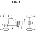
- a torque transmitting system for a four-wheel drive vehicle provided with a power plant 1 including an engine and a transmission.
- An output shaft 2 of the power plant 1 is connected with a front propeller shaft 4 through a gear train 3 and with a rear propeller shaft 6 through a power transmitting means 5 or a hydraulic variable clutch mechanism 5.
- the front propeller shaft 4 is connected with front wheels 8 through a final gear unit 7 and the rear propeller shaft 6 is connected to rear wheels 10 through a final gear unit 9.
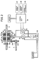
- a hydraulic pressure applied to the hydraulic clutch mechanism 5 is controlled for changing the amount of the drive torque transmitted through the clutch mechanism 5 so that a torque distribution ratio can be controlled.
- the clutch mechanism 5 includes a hydraulic clutch 11 for the front wheels 8 and a hydraulic clutch 12 for the rear wheels 10.
- the clutches 11 and 12 are disposed in a casing 13 which is divided by a wall portion 13a to define oil cylinders 14 and 15.
- the casing 13 is integrally formed with the output shaft 2 of the power plant 1 extending through the cylinders 14 and 15.
- the clutch 11 is provided with a piston 16 slidably mounted on the output shaft 2 in the cylinder 14.
- An output shaft 17 is also mounted on the output shaft 2 and engaged with the piston 16 at the rear end portion thereof.
- a spring 18 is disposed between the output shaft 2 and the piston 16 to urge the piston 16 against the wall portion 13a in the axial direction of the output shaft 2.
- the clutch 11 further includes a plurality of clutch plates 19 in meshing engagement with splines 20 formed on the rear end portion of the output shaft 2 and a plurality of clutch plates 21 in meshing engagement with splines 22 formed on the inside of the cylinder 14.
- the clutch plates 19 and 21 are alternately and slidably disposed in the cylinder 14 so that the clutch plates 19 and 21 move along the splines 20 and 22.
- the clutch plates 19 and 21 are brought into contact with each other to thereby transmit the drive torque to the output shaft 17 from output shaft 2 when the hydraulic pressure is introduced into a chamber 23 defined between the piston 16 and the wall portion 13a.
- the clutch 12 for the rear wheels 10 as well as the clutch 11 are provided with a piston 24 mounted on the shaft 17, a plurality of clutch plates 25 and 26 in meshing engagement with splines 27 on the front end portion of the output shaft 2 and with splines 28 on the inside of the casing 13, and a spring 29.
- the clutch plates 25 and 26 move along the splines 27 and 28 to be brought into contact with each other when the hydraulic pressure is introduced into a chamber 30 defined between the wall portion 13a so that the drive torque from the output shaft 2 is transmitted to the rear propeller shaft 6 for the rear wheels 10. It will be understood that the amount of the drive torque transmitted by the clutches 11 and 12 corresponds to the hydraulic pressures introduced into the chambers 23 and 30.
- the output shaft 17 of the hydraulic clutch 11 is formed with gear 31 a at the end portion thereof.
- the gear 31 a is engaged with a gear 31 provided at the end portion of the front propeller shaft 4 through an idler gear 31 b so that the clutch 11 can transmit the drive torque to the propeller shaft 4 from the output shaft 2 when the hydraulic pressure is introduced into the chamber 23.
- the hydraulic clutch 12 is connected with the front end portion of the rear propeller shaft 6.
- the clutches 11 and 12 are communicated with a hydraulic pump 32 through flow control valves 33 and 34.
- the follow control valves 33 and 34 are controlled by signals from torque control means 35 or a control unit 35.
- control oil stored in an oil tank 36 is pumped up by the pump 32 to produce a predetermined pressure and introduced into oil chambers 23 and 30 in the clutch mechanism 5 through the control valves 33, 34.
- the control valves 33, 34 are adapted to be controlled by the control unit 35 to regulate the hydraulic pressure so that the engaging force of the clutch mechanism 5, i.e. the drive torque transmitted through the clutch mechanism 5 can be controlled.
- the the control unit 35 connected are a vehicle speed detecting means or sensor 37 for detecting the vehicle speed and producing a vehicle speed signal Sv, a steering angle detecting means or sensor 38 for detecting the steered angle and producing a steered angle signal SA, a speed difference detecting means or sensor 39 for detecting rotating speed difference DN between the front propeller shaft 4 and rear propeller shaft 6 and producing a rotating speed signal SD n .
- a rotating speed sensor for detecting rotating speed of the front propeller shaft 4 may be employed as a vehicle speed sensor 37.
- a rotating speed sensor for detecting rotating speed of the rear propeller shaft 6 may be connected to the control unit 35 adapted to calculate the rotating speed difference so that the rotating speed difference DN can be obtained without employing the above speed difference sensor 39.
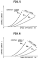
- the control unit 35 receives the signals Sv, SA, and SD n to provide the control valves 33, 34 with a control current i in accordance with control maps M 1 , M 2 , M 3 , and M 4 as shown in fig. 3 and fig. 4, fig. 5 and fig. 6 respectively.
- the control map M 1 in fig. 3 including control lines 1 1 , 1 2 and 1 3 is provided for a drive condition under a constant steered angle and various vehicle speeds. In the map Mi the rotating speed difference DN increases in accordance with an increase of the vehicle speed.
- the control unit 35 receives the signals Sv, SA, and SD n from the sensor 37, 38, and 39 to judge whether the vehicle is under a constant steered angle or under a varying steered angle condition.
- the control unit 35 selects the control map M 1 .
- the control map M 2 or another is selected in accordance with the vehicle speed.
- the control unit 35 selects a proper control line among the lines 11, 1 2 , and 1 3 in accordance with the signal SD n to determine the control current i.
- the determined current i is applied to the control valves 33, 34 so that the control valves 33, 34 produce a hydraulic pressure P in proportion to the value of the control current i to be applied to the clutch mechanism 5.
- the clutch mechanism 5 is actuated by the pressure to produce an engaging force to transmit the torque T r proportional to the hydraulic pressure P to the rear propeller shaft 6.
- the control unit 35 selects a proper control line among control lines in the map M 2 or the like in accordance with the steered angle signal SA and vehicle speed signal Sv to determine a value of the control current i based on the rotating speed difference DN.
- the torque distribution ratio for rear wheels 10 can be maintained at a constant value in accordance with the speed difference DN.
- the torque distribution ratio u may be fixed at a predetermined value in accordance with a particular speed of the vehicle and may change in accordance with vehicle operating conditions.
- the control current i can be obtained by a calculation in the control unit 35 without using the maps as described above.
- control current i may be maximized under a high speed drive condition above a predetermined vehicle speed at a small steered angle so that the front wheels are directly connected with the rear wheels.
- the control unit 35 judges whether or not vehicle speed V is larger than a predetermined value V F (step 102).
- the control unit in turn judges whether or not a steered angle A is smaller than a predetermined value Ao (step 104).
- the control unit provides the control current i with the maximum value i max (step 106) so as to maximize the torque distribution for the rear wheels.
- the control current i with the maximum value i max (step 106) so as to maximize the torque distribution for the rear wheels.
- friction wear in the clutch mechanism 5 is reduced to thereby improve the durability of the vehicle. And a stable drivability can be obtained in a straight path.
- an usual torque distribution control is carried out.
- the clutch mechanism 5 may be disposed between the front propeller shaft 4 and the power plant 1.
- FIG. 8 Another embodiment of the torque control system in accordance with the present invention is shown in Figure 8.
- a drive gear of the output shaft 2 of the power plant 1 is connected with an ring gear 48 through an intermediate gear 60.
- These gears 48 and 60 are part of a spur gear so that the axis of the ring gear 48 is parallel to the output shaft 2.
- a front differential gear mechanism 47 is extended through the central portion of the ring gear 48.
- the ring gear 48 is rotatably carried by a differential gear case 50 through a bearing device 62.
- the front differential gear mechanism 47 is provided with the differential gear case 50 rotatably carried through a bearing device 63, a pair of pinions 64 disposed in the differential gear case 50, and a pair of side gears 65 in meshing engagement with the pinions 64.
- the side gears 65 are adapted to rotate integrally with the differential gear case 50 through a shaft 61 which carries the side gears 65.
- the side gears 65 are connected with front drive shafts 41 respectively.
- the input shaft 40 is rotatably mounted on a casing C through bearings 42.
- the input shaft 40 is provided with an input gear 43 in meshing engagement with a ring gear 48 and a bevel gear 44 in meshing engagement with a pinion 45 which is integrated with the rear propeller shaft 6.
- the rear propeller shaft 6 is connected with the rear wheels 10 through a rear differential gear mechanism (not shown).
- a wet clutch 46 which can change a torque transmitted therethrough is disposed between the front differential gear mechanism 47 and the ring gear 48.
- the clutch 46 is provided with a clutch drum 49 which is integrally formed with the differential gear case 50.
- the drum 49 is engaged with a tubular portion 51 which covers one of the drive shafts 41.
- the clutch drum 49 rotatably holds a plurality of driven plates 52.
- the holding portion 48a of the ring gear 48 holds a plurality of drive plates 53.
- a piston 54 is slidably disposed in the clutch drum 49 to define an oil chamber S so that the piston 54 moves to bring the plates 52 into pressure engagement with the plates 53 when the hydraulic pressure is introduced into the chamber S.
- the driving force provided by the piston 54 finally acts on the clutch drum 49 through the plates 52 and 53, an end plate 55 and a snap ring 56.
- the clutch drum 49 or the front differential gear mechanism 47 is connected with the ring gear 48 by means of a frictional force corresponding to the hydraulic pressure.
- the hydraulic pressure is introduced into the oil chamber S through an inlet 57 formed in the clutch drum 49, an oil passage 58 in the differential gear case 50, and an oil passage 59 in the casing C.
- the clutch 46 is disengaged.
- drive torque from the power unit 1 is transmitted to the ring gear 48 through the intermediate gear 60.
- the drive torque is transmitted to the rear wheel drive mechanism B through the input gear 43.
- the drive torque is transmitted from the ring gear 48 to the front differential gear mechanism 47 through the clutch 46.
- the frictional force in the clutch 46 is controlled in accordance with the hydraulic pressure so that the torque distribution ratio between the front wheels 8 and rear wheels 10 can be broadly controlled from 0:100 to 50:50. In this case, the amount of the torque to the rear wheels 10 can be provided more than that of the front wheels 8 so that a stable drivability can be obtained.
- the structure of the torque control system as aforementioned in connection with fig. 2 can also accomplish the improved torque control in accordance with the present invention.
Landscapes
- Engineering & Computer Science (AREA)
- Chemical & Material Sciences (AREA)
- Combustion & Propulsion (AREA)
- Transportation (AREA)
- Mechanical Engineering (AREA)
- Arrangement And Driving Of Transmission Devices (AREA)
Claims (9)
Applications Claiming Priority (6)
| Application Number | Priority Date | Filing Date | Title |
|---|---|---|---|
| JP191035/85 | 1985-08-30 | ||
| JP19103585A JPS6250229A (ja) | 1985-08-30 | 1985-08-30 | 4輪駆動車の伝達トルク制御装置 |
| JP19103385A JPS6250227A (ja) | 1985-08-30 | 1985-08-30 | 4輪駆動車の伝達トルク制御装置 |
| JP191033/85 | 1985-08-30 | ||
| JP206271/85 | 1985-09-20 | ||
| JP20627185A JPS6268136A (ja) | 1985-09-20 | 1985-09-20 | 4輪駆動車の駆動力伝達装置 |
Publications (2)
| Publication Number | Publication Date |
|---|---|
| EP0215352A1 EP0215352A1 (fr) | 1987-03-25 |
| EP0215352B1 true EP0215352B1 (fr) | 1990-01-31 |
Family
ID=27326437
Family Applications (1)
| Application Number | Title | Priority Date | Filing Date |
|---|---|---|---|
| EP86111919A Expired - Lifetime EP0215352B1 (fr) | 1985-08-30 | 1986-08-28 | Système de commande du couple pour véhicules |
Country Status (3)
| Country | Link |
|---|---|
| US (1) | US4709775A (fr) |
| EP (1) | EP0215352B1 (fr) |
| DE (1) | DE3668586D1 (fr) |
Cited By (1)
| Publication number | Priority date | Publication date | Assignee | Title |
|---|---|---|---|---|
| DE102005014913A1 (de) * | 2005-04-01 | 2006-10-05 | Zf Friedrichshafen Ag | Getriebevorrichtung, insbesondere Hinterachsgetriebevorrichtung eines Fahrzeugs |
Families Citing this family (24)
| Publication number | Priority date | Publication date | Assignee | Title |
|---|---|---|---|---|
| US4896738A (en) * | 1986-06-20 | 1990-01-30 | Fuji Jukogyo Kabushiki Kaisha | Power transmitting system for a four-wheel drive vehicle |
| US4884653A (en) * | 1986-08-08 | 1989-12-05 | Toyota Jidosha Kabushiki Kaisha | Method of controlling a four wheel drive vehicle |
| AT390408B (de) * | 1986-10-21 | 1990-05-10 | Steyr Daimler Puch Ag | Antriebsanordnung fuer allradgetriebene kraftfahrzeuge |
| JPS63240430A (ja) * | 1987-03-27 | 1988-10-06 | Toyoda Mach Works Ltd | 駆動力伝達装置 |
| JPH0448349Y2 (fr) * | 1987-04-20 | 1992-11-13 | ||
| JP2527204B2 (ja) * | 1987-10-09 | 1996-08-21 | 日産自動車株式会社 | 四輪駆動車の駆動力配分制御装置 |
| US4936406A (en) * | 1987-10-23 | 1990-06-26 | Fuji Jukogyo Kabushiki Kaisha | Power transmitting system for a four-wheel drive vehicle |
| JPH01114523A (ja) * | 1987-10-27 | 1989-05-08 | Fuji Heavy Ind Ltd | 4輪駆動車の駆動力制御装置 |
| JP2615085B2 (ja) * | 1987-10-27 | 1997-05-28 | 富士重工業株式会社 | 4輪駆動車のトラクション制御装置 |
| DE3811214C2 (de) * | 1988-04-02 | 1994-04-21 | Porsche Ag | Anordnung zur Steuerung der Kraftübertragung auf wenigstens zwei Achsen eines Kraftfahrzeuges |
| JP2726896B2 (ja) * | 1988-08-31 | 1998-03-11 | アイシン精機株式会社 | 4輪駆動車の駆動力制御方法及び装置 |
| US4949594A (en) * | 1989-03-31 | 1990-08-21 | Ford Motor Company | Interaxle differential for full time all wheel drive system |
| DE4031036A1 (de) * | 1989-09-30 | 1991-05-02 | Mazda Motor | Antriebssteuersystem fuer fahrzeug mit vierradantrieb |
| IT1238112B (it) * | 1989-10-10 | 1993-07-07 | Fiat Auto Spa | Trasmissione a trazione integrale disinseribile per autoveicoli |
| US5127887A (en) * | 1989-10-27 | 1992-07-07 | Nuttall John B | Vehicle driveline |
| US5477452A (en) * | 1993-07-15 | 1995-12-19 | Saturn Corporation | Upshift indicator for manual transmission |
| JP3275563B2 (ja) * | 1994-09-21 | 2002-04-15 | 日産自動車株式会社 | 車両の四輪駆動制御装置 |
| AT7553U1 (de) | 2004-02-23 | 2005-05-25 | Magna Drivetrain Ag & Co Kg | Antriebsstrang eines allradgetriebenen fahrzeuges |
| AT8907U1 (de) * | 2005-07-29 | 2007-02-15 | Magna Drivetrain Ag & Co Kg | Verteilergetriebe mit zwei voneinander unabhängigen kupplungen zur steuerung der momentenverteilung auf zwei achsen, kupplung für ein solches und verfahren zu deren kalibrierung |
| US7920949B2 (en) * | 2007-05-22 | 2011-04-05 | Caterpillar Inc. | Feedback adjustment for open-loop torque control map |
| US8000863B2 (en) * | 2007-05-31 | 2011-08-16 | Caterpillar Inc. | Open-loop torque control with closed-loop feedback |
| JP5144304B2 (ja) * | 2008-02-22 | 2013-02-13 | 本田技研工業株式会社 | 車両の後輪操舵装置 |
| DE102010052270A1 (de) * | 2010-11-23 | 2013-05-16 | Liebherr Mining Equipment Co. | Verfahren und Vorrichtung zum Steuern des Antriebssystems für mobile Geräte wie eine mobile Bau- und/oder Abbaumaschine |
| US10377232B2 (en) | 2015-05-12 | 2019-08-13 | Dana Automotive Systems Group, Llc | Method for synchronization control of rapid connect AWD systems |
Citations (4)
| Publication number | Priority date | Publication date | Assignee | Title |
|---|---|---|---|---|
| US3773130A (en) * | 1969-05-12 | 1973-11-20 | O Mueller | Variable torque transmission |
| US3963085A (en) * | 1974-10-17 | 1976-06-15 | Caterpillar Tractor Co. | Planetary four wheel drive system having plural modes of operation |
| EP0043237A1 (fr) * | 1980-06-27 | 1982-01-06 | Fuji Jukogyo Kabushiki Kaisha | Système de commande pour une transmission de véhicule |
| EP0076148A1 (fr) * | 1981-09-29 | 1983-04-06 | Fuji Jukogyo Kabushiki Kaisha | Système de commande pour le couple de transmission d'un véhicule à quatre roues motrices |
Family Cites Families (4)
| Publication number | Priority date | Publication date | Assignee | Title |
|---|---|---|---|---|
| JPS5835773B2 (ja) * | 1980-02-29 | 1983-08-04 | 松下電工株式会社 | 金型の固定装置 |
| JPS58133922A (ja) * | 1982-01-29 | 1983-08-09 | Fuji Heavy Ind Ltd | 4輪駆動車の切換制御装置 |
| JPS59109431A (ja) * | 1982-12-16 | 1984-06-25 | Fuji Heavy Ind Ltd | 4輪駆動車の切換制御装置 |
| JPS6064033A (ja) * | 1983-09-19 | 1985-04-12 | Fuji Heavy Ind Ltd | 4輪駆動車の自動切換制御方法 |
-
1986
- 1986-08-28 DE DE8686111919T patent/DE3668586D1/de not_active Expired - Fee Related
- 1986-08-28 EP EP86111919A patent/EP0215352B1/fr not_active Expired - Lifetime
- 1986-08-29 US US06/901,776 patent/US4709775A/en not_active Expired - Fee Related
Patent Citations (4)
| Publication number | Priority date | Publication date | Assignee | Title |
|---|---|---|---|---|
| US3773130A (en) * | 1969-05-12 | 1973-11-20 | O Mueller | Variable torque transmission |
| US3963085A (en) * | 1974-10-17 | 1976-06-15 | Caterpillar Tractor Co. | Planetary four wheel drive system having plural modes of operation |
| EP0043237A1 (fr) * | 1980-06-27 | 1982-01-06 | Fuji Jukogyo Kabushiki Kaisha | Système de commande pour une transmission de véhicule |
| EP0076148A1 (fr) * | 1981-09-29 | 1983-04-06 | Fuji Jukogyo Kabushiki Kaisha | Système de commande pour le couple de transmission d'un véhicule à quatre roues motrices |
Cited By (1)
| Publication number | Priority date | Publication date | Assignee | Title |
|---|---|---|---|---|
| DE102005014913A1 (de) * | 2005-04-01 | 2006-10-05 | Zf Friedrichshafen Ag | Getriebevorrichtung, insbesondere Hinterachsgetriebevorrichtung eines Fahrzeugs |
Also Published As
| Publication number | Publication date |
|---|---|
| DE3668586D1 (de) | 1990-03-08 |
| EP0215352A1 (fr) | 1987-03-25 |
| US4709775A (en) | 1987-12-01 |
Similar Documents
| Publication | Publication Date | Title |
|---|---|---|
| EP0215352B1 (fr) | Système de commande du couple pour véhicules | |
| US4846298A (en) | Driving force distribution control system for 4WD vehicle | |
| US4887689A (en) | Driving force distribution control system for 4WD vehicle | |
| US5456641A (en) | Left/right drive torque adjusting apparatus for vehicle and left/right drive torque adjusting method for vehicle | |
| EP0311141B1 (fr) | Commande de la force motrice pour véhicule à quatre roues motrices | |
| EP0413436B1 (fr) | Commande de répartition du couple pour véhicule automobile à quatre roues motrices | |
| US4754834A (en) | Four wheel drive system having driving force distribution control responsive to vehicle lateral acceleration | |
| US4936406A (en) | Power transmitting system for a four-wheel drive vehicle | |
| EP0364435B1 (fr) | Differentiel variable en continu | |
| EP0157581B1 (fr) | Système de commande pour un véhicule à quatre roues motrices | |
| EP0409529B1 (fr) | Système de régulation pour la répartition du moment de couple sur un véhicule à quatre roues | |
| EP0319830B1 (fr) | Dispositif pour la distribution de la force motrice dans un véhicule à quatre roues motrices | |
| US4773517A (en) | Torque control system for vehicles | |
| EP0282187B1 (fr) | Transmission de puissance pour véhicule à quatre roues motrices | |
| EP0421594B1 (fr) | Commande de répartition du couple pour véhicule à moteur à quatre roues motrices | |
| EP0415554A1 (fr) | Commande de répartition du couple pour véhicule automobile à quatre roues motrices | |
| EP0332418B1 (fr) | Système de commande d'un couple de transfert pour un véhicule à quatre roues motrices | |
| EP0395304A1 (fr) | Système de transmission avec différential pour véhicule motorisé | |
| EP0262908B1 (fr) | Système pour commander un accouplement de transfert d'un véhicule à entraînement sur les quatre roues | |
| JPS62103226A (ja) | 車両用差動制限制御装置 | |
| JPH0933550A (ja) | 車輪速検出装置 | |
| JPS62143720A (ja) | 四輪駆動車の駆動力配分制御装置 | |
| JPH0567443B2 (fr) | ||
| JPH0536251B2 (fr) | ||
| EP0295738B1 (fr) | Procédé pour la commande d' un véhicule à propulsion débrayable à quatre roues |
Legal Events
| Date | Code | Title | Description |
|---|---|---|---|
| PUAI | Public reference made under article 153(3) epc to a published international application that has entered the european phase |
Free format text: ORIGINAL CODE: 0009012 |
|
| AK | Designated contracting states |
Kind code of ref document: A1 Designated state(s): DE FR GB |
|
| 17P | Request for examination filed |
Effective date: 19870506 |
|
| 17Q | First examination report despatched |
Effective date: 19880224 |
|
| GRAA | (expected) grant |
Free format text: ORIGINAL CODE: 0009210 |
|
| AK | Designated contracting states |
Kind code of ref document: B1 Designated state(s): DE FR GB |
|
| REF | Corresponds to: |
Ref document number: 3668586 Country of ref document: DE Date of ref document: 19900308 |
|
| ET | Fr: translation filed | ||
| PLBE | No opposition filed within time limit |
Free format text: ORIGINAL CODE: 0009261 |
|
| STAA | Information on the status of an ep patent application or granted ep patent |
Free format text: STATUS: NO OPPOSITION FILED WITHIN TIME LIMIT |
|
| 26N | No opposition filed | ||
| PGFP | Annual fee paid to national office [announced via postgrant information from national office to epo] |
Ref country code: FR Payment date: 19960809 Year of fee payment: 11 |
|
| PGFP | Annual fee paid to national office [announced via postgrant information from national office to epo] |
Ref country code: GB Payment date: 19960819 Year of fee payment: 11 |
|
| PG25 | Lapsed in a contracting state [announced via postgrant information from national office to epo] |
Ref country code: GB Free format text: LAPSE BECAUSE OF NON-PAYMENT OF DUE FEES Effective date: 19970828 |
|
| PGFP | Annual fee paid to national office [announced via postgrant information from national office to epo] |
Ref country code: DE Payment date: 19970905 Year of fee payment: 12 |
|
| GBPC | Gb: european patent ceased through non-payment of renewal fee |
Effective date: 19970828 |
|
| PG25 | Lapsed in a contracting state [announced via postgrant information from national office to epo] |
Ref country code: FR Free format text: LAPSE BECAUSE OF NON-PAYMENT OF DUE FEES Effective date: 19980430 |
|
| REG | Reference to a national code |
Ref country code: FR Ref legal event code: ST |
|
| PG25 | Lapsed in a contracting state [announced via postgrant information from national office to epo] |
Ref country code: DE Free format text: LAPSE BECAUSE OF NON-PAYMENT OF DUE FEES Effective date: 19990601 |