EP0818574A2 - Dispositif de nettoyage - Google Patents
Dispositif de nettoyage Download PDFInfo
- Publication number
- EP0818574A2 EP0818574A2 EP97106506A EP97106506A EP0818574A2 EP 0818574 A2 EP0818574 A2 EP 0818574A2 EP 97106506 A EP97106506 A EP 97106506A EP 97106506 A EP97106506 A EP 97106506A EP 0818574 A2 EP0818574 A2 EP 0818574A2
- Authority
- EP
- European Patent Office
- Prior art keywords
- roller
- cleaning
- cleaning device
- nozzle
- pressure
- Prior art date
- Legal status (The legal status is an assumption and is not a legal conclusion. Google has not performed a legal analysis and makes no representation as to the accuracy of the status listed.)
- Granted
Links
Images

Classifications
-
- B—PERFORMING OPERATIONS; TRANSPORTING
- B08—CLEANING
- B08B—CLEANING IN GENERAL; PREVENTION OF FOULING IN GENERAL
- B08B3/00—Cleaning by methods involving the use or presence of liquid or steam
- B08B3/02—Cleaning by the force of jets or sprays
- B08B3/022—Cleaning travelling work
-
- D—TEXTILES; PAPER
- D21—PAPER-MAKING; PRODUCTION OF CELLULOSE
- D21G—CALENDERS; ACCESSORIES FOR PAPER-MAKING MACHINES
- D21G3/00—Doctors
Definitions
- the invention relates to a cleaning device for cleaning a roller in a paper machine, with an injection device for spraying the roller with a cleaning medium and a Device for removing the cleaning medium from the Roller surface.
- rollers are used in a paper machine, that come into contact with the paper web. In the course of operation these are contaminated in the paper machine, for example with paper fibers, adhesives or other additives added.
- the pores of ceramic rollers can also coalesce Filler, e.g. with calcium carbonate.
- rollers must therefore be used during the operation of the paper machine are constantly cleaned. This is usually done used two scrapers arranged one behind the other, between which liquid is sprayed onto the roller surface.
- the object of the invention is therefore a cleaning device for cleaning a roller in a paper machine to create with an improved cleaning effect too can be achieved if the roller is very dirty.
- this object is achieved in that Cleaning device according to the type mentioned Spraying device as a high-pressure spraying device with a Working pressure of at least 10 bar is formed.
- the device according to the invention can be particularly advantageous for cleaning smooth rollers, such as ceramic or Use granite rollers that are particularly vulnerable to Soiling e.g. due to the deposit of calcium carbonate exhibit.
- the high pressure spray device itself can be more preferred Further development of the invention either at least one needle jet spray tube or comprise at least one high pressure rotary nozzle.
- the high-pressure spray device comprises at least one needle spray tube, parallel to the Longitudinal axis of the roller is arranged and a plurality of High pressure needle nozzles included, which are in the longitudinal direction of the roller are distributed.
- the High-pressure spray device at least one needle jet spray tube with a plurality of one behind the other in the direction of rotation of the roller arranged high pressure needle nozzles, which on a traversing trolley is arranged, back and forth in the longitudinal direction of the roller is traversable.
- the traversing trolley can cover a large area Cleaning effect can be achieved, so that even with relative the entire roller surface with just a few high pressure needle nozzles can be cleaned.
- the needle spray tube is preferably at a pressure of operated at least 40 bar in order to be particularly intensive To achieve cleaning effect.
- the High-pressure injection device at least one rotary nozzle device, with a working pressure of at least 50 bar, preferably with a working pressure of about 100 to 250 bar, is operated.
- At least a rotary nozzle device from one to the roll surface open suction cup enclosed by a vacuum is acted upon.
- the suction cup is open on the roller surface Page suitably adapted to the shape of the roller surface and preferably by an elastic sheath or a Brush edge sealed against this.
- the rotary nozzle device an axis of rotation that is opposite to the surface normal the roll surface is inclined.
- the rotary nozzle device can a nozzle head with at least one cleaning nozzle have, against the axis of rotation of the rotary nozzle device is inclined.
- the Rotary nozzle device a nozzle head with at least one Nozzle whose nozzle diameter is 0.1 mm to 0.8 mm, preferably 0.2 mm to 0.4 mm, in particular 0.2 mm to 0.4 mm.
- a plurality of rotary nozzle devices in front of the roll surface arranged over the entire width of the roller.
- the at least a rotary nozzle device is arranged on a traversing carriage, which can be traversed back and forth in the longitudinal direction of the roller is.
- This measure has the advantage that the additional Superposition with the speed component of the back and forth moving traversing car further intensification of Cleaning effect is achieved. Furthermore, there are fewer Rotary nozzle devices required to cover the entire To clean the roller surface. This way, in addition the consumption of cleaning fluid can be restricted.
- This flushing device is expediently used as a flat jet spray tube trained, which is parallel to the roller surface extends in the longitudinal direction of the roller.
- the roller seen at least in front of the high-pressure spraying device a scraper arranged.
- the means for removing the Cleaning medium at least one in the direction of rotation of the roller seen behind the high pressure sprayer or behind the Includes scraper arranged scraper.
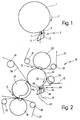
- a roller 1 is shown with a cleaning device 2 is equipped according to the state of the art.
- the Roller 1 can be designed in particular as a ceramic or granite roller be those who are particularly susceptible to incrustation e.g. due to calcium carbonate.
- the cleaning device 2 comprises a scraper bar 5 which a spray device 6 for spraying the roller 1 between one in the direction of rotation 7 of the roller 1 over the entire Roller width extending scraper 3 and a second, the Spray device 6 in the direction of rotation 7 downstream scraper 4 is arranged, which is also over the entire width of the roller extends.
- Fig. 2 is a press section of a paper machine, the is shown schematically, overall with the number 10 designated.
- a cleaning device according to the invention provided that is generally designated with the number 40.
- a paper web 12 does not come from an upstream one shown screen section on one over different deflection rollers, only one of which is shown at 29 is guided felt 28 to a first press nip 14 by a lower shoe press roll 18 and an upper one Suction roll 20 is formed. Through the press nip 14 is also a lower press felt 27 is guided over deflection rollers 25, 26th circulates.
- the paper web 12 becomes smooth Pass central roller 24, which are designed as a ceramic roller can and with a shoe press roll 22 forms a second press nip 16.
- a shoe press roll 22 forms a second press nip 16.
- Through the second press nip 16 is also a top felt 32 over two deflecting rollers 30, 31 guided.
- the paper web 12 After leaving the second press nip 16, the paper web 12 removed from the roller 24 by means of a suction roller 33 and reaches a subsequent press nip or becomes immediate handed over to a subsequent dryer section.
- the cleaning device according to the invention is for cleaning the roller 24 40 provided.
- the cleaning device 40 comprises a first scraper 42, which is held on a scraper bar 45, obliquely against the Roll surface is adjusted and over the entire width the roller 24 extends.
- Parallel to the scraper 42 is in Direction of rotation 23 of the roller 24 arranged downstream of a needle spray tube 46 provided that also extends over the entire Roller width and comprises a plurality of needle nozzles, as will be explained below with reference to FIG. 3.
- the needle spray tube is at a pressure of at least 10 bar, preferably operated at a pressure of more than 40 bar and enables intensive through the numerous needle nozzles Cleaning the roller 24.
- the needle spray tube 46 in the direction of rotation 23 a rinsing device is also arranged downstream of the roller 24, which is formed by a flat spray tube 48 is also parallel to the surface of the roller 24 extends over the entire width of the roller.
- the flat spray wand 48 will start with a significantly larger throughput Cleaning fluid operated as via the needle spray tube 46 exits.
- the flat jet spray tube 48 causes the suspension dirt particles previously loosened by the needle jet spray tube 46 reached, so that this is subsequently by a subordinate second scraper 44 slightly from the surface of roller 24 can be removed.
- the second scraper 44 By the second scraper 44, the is also positioned obliquely against the roller surface, a dry roller surface is ensured and thus the formation of wet streaks on the paper web 12 is prevented.
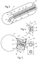
- the needle jet spray tube 46 comprises a plurality of needle nozzles 50, which are preferably somewhat obliquely opposite the Direction of rotation 23 are set against the roller surface.
- the flat jet spray tube 48 comprises a plurality of flat jet nozzles 52, through the cleaning liquid onto the roller surface is rinsed.
- the needle jet spray tube 46 is connected via a line 47 Cleaning liquid at a pressure of at least 10 bar, preferably supplied by more than 40 bar, while the flat jet spray pipe 48 only with a slight pressure, however is operated with a significantly larger flow.
- Water is usually used as the cleaning liquid, where appropriate, in particular that of the needle spray tube 46 supplied cleaning liquid still the Cleaning effect-improving additives can be added.
- FIGS. 2 and 3 are purely schematic and not the actual one Corresponds to size relationships. The same applies to the following figures with which modifications of the previously described Cleaning device will be explained.
- roller 4 is a cleaning device for cleaning the Roller 24 designated overall by the number 70.
- the cleaning device 70 in turn comprises a needle spray tube 76, the one upstream in the direction of rotation 23 first scraper 72 and a downstream scraper 74 is arranged.
- the needle spray tube 76 is not parallel arranged to the roll surface, but extends in Direction of rotation 23 of the roller 24 over a curved area parallel to the roller surface. To nevertheless over the roller 24 To be able to clean their entire width is the needle spray tube 76 in a direction transverse to the direction of rotation 23 Roller 24 movably arranged on a traversing carriage 71.
- the traversing carriage 71 is parallel on cross beams 77 led to the roller surface and is not shown by a Traverse motor with a predeterminable speed driven, the traversing speed usually can be in a range of about 0.3 m per minute.
- FIG. 5 Another embodiment of the invention is illustrated in FIG. 5 described.
- the high pressure sprayer is not through the needle nozzles of a needle spray tube but through formed at least one rotary nozzle device.
- the cleaning device designated overall by the number 80 in the case shown includes a total of 86 designated rotary nozzle device with a suction cup 91 is combined and on a traversing carriage 81 across Roll surface can be moved back and forth across the entire width of the roll and to which a flat jet spray pipe 88 connects that parallel to the roll surface over the entire Roll width runs.
- a scraper is arranged upstream of the roller 24 in the direction of rotation 23 82 is provided, which is held on a scraper beam 83 and is inclined against the roller surface.
- the flat spray gun 88 is followed by a second scraper 84, which is held on a scraper bar 85 and also light set against the direction of rotation 23 on the roller surface is.
- the rotary nozzle device 86 is via a high pressure line with a water pressure in the range between about 50 and 1,000 bar, preferably in the range of about 100 to 250 bar, supplied and has a nozzle head 96 which is tangential over one or more outflowing propelling nozzles in a rotational movement in the area from about 2,000 to 3,000 revolutions per minute.
- the nozzle head 96 has one or more cleaning nozzles, through which the roller surface with a cleaning medium is applied.
- the interior of the suction bell 91 is in flow with one Suction line 93 connected and forms one of the rotary nozzle device 86 assigned suction chamber 97.
- the suction bell 91 on the side of the surface open to the roller surface adapted to the roller 24 and at its edges by a brush edge 95 or by an elastic sheath against the Sealed surface of the roller 24.
- the rotary nozzle device 86 is with its axis of rotation 99 slightly oblique against the direction of rotation 23 compared to the Surface normals set on the roller surface.
- the nozzle head 96 rotating rapidly in the direction of arrow 90 high pressure cleaning jets occur at different angles of attack towards the surface of roller 24, as by the arrows 92 is indicated.
- Due to the inclination of the axis of rotation 99 is in connection with the back and forth traversing Movement of the traversing carriage 81 has a particularly strong cleaning effect reached. This will also add to this reinforces that the cleaning nozzles provided on the nozzle head 96 100 are inclined relative to the axis of rotation 99, such as will be clarified with reference to Figures 6 and 7.
- the structure of the nozzle head 96 is now based on the figures 6 and 7 explained in more detail.
- the nozzle head 96 is by means of a Bearing 98 rotatably held on a flange 105. Inside the Flange 105, a stationary nozzle feed line 101 is provided, which opens into a pressure chamber 106, whose walls 103 against the Sealing inside of a cylindrical component 102, however slidable.
- the cylindrical member 102 has four openings arranged at an angle of 90 ° to each other.
- In this nozzle inlets 104 are connected, which radially follow extend outside and in its end section by preferably 90 ° are bent, as can be seen in Fig. 7.
- the nozzle feed lines 104 finally end in inclined cleaning nozzles 100, such as can be seen from Fig. 6.
- the propellant nozzles also provided are not shown.
- FIGS. 6 and 7 is only ever one of the nozzle feed lines 104 with pressure pressurized while the remaining nozzle feed lines 104 are depressurized are.
- the pressure chamber 106 is now oriented so that the liquid jet one of the direction of rotation 23 of the roller 24 opposite Has speed component, so that the Cleaning effect is particularly high. So the nozzles whose liquid jet has a velocity component in Direction of rotation 23 of the roller 24 would have no pressure and thus deactivated to reduce water consumption.
- the nozzle head 96 can also be pivoted with one or more mounted individual nozzles performing an oscillating movement be equipped, which during the traversing movement of the Nozzle head 96 sweep a band-shaped area of the roller 24.
Landscapes
- Paper (AREA)
- Cleaning By Liquid Or Steam (AREA)
- Cleaning In General (AREA)
Applications Claiming Priority (2)
| Application Number | Priority Date | Filing Date | Title |
|---|---|---|---|
| DE19627973A DE19627973A1 (de) | 1996-07-11 | 1996-07-11 | Reinigungsvorrichtung |
| DE19627973 | 1996-07-11 |
Publications (3)
| Publication Number | Publication Date |
|---|---|
| EP0818574A2 true EP0818574A2 (fr) | 1998-01-14 |
| EP0818574A3 EP0818574A3 (fr) | 1999-01-20 |
| EP0818574B1 EP0818574B1 (fr) | 2003-03-19 |
Family
ID=7799563
Family Applications (1)
| Application Number | Title | Priority Date | Filing Date |
|---|---|---|---|
| EP97106506A Expired - Lifetime EP0818574B1 (fr) | 1996-07-11 | 1997-04-19 | Dispositif de nettoyage |
Country Status (4)
| Country | Link |
|---|---|
| US (1) | US5964960A (fr) |
| EP (1) | EP0818574B1 (fr) |
| CA (1) | CA2208288A1 (fr) |
| DE (2) | DE19627973A1 (fr) |
Cited By (2)
| Publication number | Priority date | Publication date | Assignee | Title |
|---|---|---|---|---|
| EP1179631A1 (fr) * | 2000-08-11 | 2002-02-13 | Voith Paper Patent GmbH | Dispositif de nettoyage et/ou de conditionnement |
| EP2127879A1 (fr) * | 2008-05-27 | 2009-12-02 | Fischer & Krecke GmbH | Dispositif de nettoyage pour cylindre d'une presse d'impression rotative |
Families Citing this family (35)
| Publication number | Priority date | Publication date | Assignee | Title |
|---|---|---|---|---|
| DE69919538T2 (de) * | 1998-01-20 | 2005-09-08 | Metso Paper, Inc. | Verfahren ung vorrichtung zur konditionierung einer walze, insbesondere von einer walze in einer papierherstellungs- oder veredelungsvorrichtung |
| DE19810800A1 (de) * | 1998-03-12 | 1999-09-16 | Voith Sulzer Papiertech Patent | Pressenanordnung |
| DE19822185A1 (de) * | 1998-05-16 | 1999-11-18 | Voith Sulzer Papiertech Patent | Vorrichtung und Verfahren zum Reinigen eines Transportbandes |
| DE19901802B4 (de) * | 1999-01-19 | 2004-02-12 | Baldwin Germany Gmbh | Vorrichtung zur Rückbefeuchtung einer getrockneten Papierbahn |
| US6630035B1 (en) * | 1999-08-18 | 2003-10-07 | Fuji Photo Film Co., Ltd. | Cleaning unit for recording rotational drum and cleaning method |
| US6360758B1 (en) * | 1999-09-10 | 2002-03-26 | Metso Paper, Inc. | Cleaning device in paper machines, board machines or other similar machines for cleaning a fabric, such as wire or felt |
| US6451126B1 (en) * | 1999-10-05 | 2002-09-17 | Walter Mattix | Method for cleaning the machine frames of a pulp paper processing dryer |
| US6468397B1 (en) * | 1999-12-20 | 2002-10-22 | Kimberly-Clark Worldwide, Inc. | Scarfing shower for fabric cleaning in a wet papermaking process |
| DE20013887U1 (de) * | 2000-08-11 | 2000-10-26 | Voith Sulzer Papiertechnik Patent GmbH, 89522 Heidenheim | Konditionier- und/oder Reinigungsvorrichtung |
| DE10197007T1 (de) * | 2000-12-08 | 2003-10-16 | Metso Paper Karlstad Ab Karlst | Verfahren und Vorrichtung zum Entfernen von Wasser von der Oberfläche eines Walzenmantels |
| FI115312B (fi) * | 2001-02-14 | 2005-04-15 | Metso Paper Inc | Puhdistuslaitteisto paperin tai kartongin viimeistelylaitetta varten |
| DE10121679A1 (de) * | 2001-05-04 | 2002-11-07 | Voith Paper Patent Gmbh | Verfahren und Vorrichtung zur Reinigung eines Wickelkerns einer Papier- oder Kartonmaschine |
| US7047852B2 (en) * | 2001-10-24 | 2006-05-23 | Kimberly-Clark Worldwide, Inc. | Feedforward control system for an elastic material |
| US6799514B2 (en) * | 2002-01-11 | 2004-10-05 | The Procter & Gamble Company | Cleaning apparatus for printing press |
| FI110761B (fi) * | 2002-03-22 | 2003-03-31 | Metso Paper Inc | Puhdistuslaitteisto liikkuvan pinnan puhdistamiseksi erityisesti paperikoneessa |
| DE10321706A1 (de) * | 2003-05-14 | 2004-12-02 | Voith Paper Patent Gmbh | Reinigungssytem für eine Abnahmesaugwalze |
| US7101832B2 (en) * | 2003-06-19 | 2006-09-05 | Johnsondiversey, Inc. | Cleaners containing peroxide bleaching agents for cleaning paper making equipment and method |
| DE10329675A1 (de) * | 2003-07-01 | 2005-02-03 | Voith Paper Patent Gmbh | Verfahren und Vorrichtung zur Herstellung und/oder Behandlung einer Faserstoffbahn |
| DE102004006629B3 (de) * | 2004-02-10 | 2005-11-17 | Sundwig Gmbh | Vorrichtung zum Reinigen der Oberfläche von zylindrischen Körpern, wie Walzen oder Rollen |
| DE102004028552A1 (de) * | 2004-06-15 | 2006-01-05 | Robo Paper B.V. | Vorrichtung mit Waschdüsen und Verfahren zum Reinigen einer umlaufenden Auftragseinrichtung |
| US7077260B2 (en) * | 2004-06-29 | 2006-07-18 | Gerald Michael Saballus | Device for cleaning corrugator belts |
| DE102005022035A1 (de) * | 2004-10-22 | 2006-04-27 | Robo Paper B.V. | Vorrichtung und Verfahren zum Reinigen einer Matrialbahn sowie Verfahren zum Herstellen eines Speedup-Cleaning-Heads |
| DE102007028341A1 (de) * | 2007-06-15 | 2008-12-18 | Robo Paper B.V. | Vorrichtung und Verfahren zum Reinigen eines umlaufenden Bahnelementes |
| US7988828B2 (en) * | 2008-09-29 | 2011-08-02 | Kimberly-Clark Worldwide, Inc. | Surface treating tissue webs via patterned spraying |
| US8771473B2 (en) * | 2009-12-11 | 2014-07-08 | Valmet Technologies, Inc. | Doctor blade for a fiber web machine and doctor arrangement in a fiber web machine |
| DE102009059790B4 (de) * | 2009-12-21 | 2017-03-30 | Paprima Industries Inc. | Reinigungsvorrichtung |
| FI20125223L (fi) * | 2012-02-28 | 2013-08-29 | Metso Paper Inc | Laitteisto ja menetelmä telan puhdistamiseksi kuiturainakoneella |
| TWI576174B (zh) * | 2013-01-18 | 2017-04-01 | Chan Li Machinery Co Ltd | Automatic cleaning device |
| US9919399B2 (en) | 2013-09-17 | 2018-03-20 | Nucor Corporation | Roll polisher apparatus and method |
| DE102014004487A1 (de) | 2014-03-28 | 2015-10-15 | Thyssenkrupp Ag | Vorrichtung zur berührungslosen Walzenreinigung und Verfahren hierfür |
| KR102472281B1 (ko) | 2019-01-25 | 2022-12-01 | 주식회사 엘지에너지솔루션 | 전극의 압연 롤 세정장치 및 세정방법 |
| DE102019105227B4 (de) * | 2019-03-01 | 2021-04-01 | Voith Patent Gmbh | Schaber mit Wasserschmierung |
| ES3036214T3 (en) * | 2020-02-13 | 2025-09-16 | Kadant Nordic AB | Cleaning head with directional nozzle assembly and shaped external air knife for traversing shower systems |
| EP4382217B1 (fr) * | 2022-12-06 | 2024-12-04 | Carl Zeiss Vision International GmbH | Dispositif de nettoyage et procédé de nettoyage de substrats montés sur un support de substrat en forme de cartouche |
| CN120155855B (zh) * | 2025-05-19 | 2025-07-29 | 邢台邢冶机械设备有限公司 | 一种轧辊生产用高效抛光设备 |
Family Cites Families (21)
| Publication number | Priority date | Publication date | Assignee | Title |
|---|---|---|---|---|
| US3177799A (en) * | 1963-01-10 | 1965-04-13 | Beloit Corp | Apparatus for selectively temperature conditioning calenders |
| US3617441A (en) * | 1968-08-22 | 1971-11-02 | United Board & Carton Corp | Spray nozzle device for cleaning accumulations in suction roll openings |
| GB1435909A (en) * | 1972-12-13 | 1976-05-19 | Jwi Ltd | Spreader shower for paper making apparatus |
| US4087320A (en) * | 1976-09-03 | 1978-05-02 | Huyck Corporation | Apparatus for cleaning an endless belt having an affixed signal element |
| SE402138B (sv) * | 1976-10-18 | 1978-06-19 | Karlstad Mekaniska Ab | Spritsrorsanordning for rengorign av viror, filtar och dylikt i pappers- och liknande maskiner |
| AT385297B (de) * | 1985-12-23 | 1988-03-10 | Andritz Ag Maschf | Vorrichtung im bereich der oberflaeche von walzen bzw. zylindern fuer bzw. an eine(r) maschine zum herstellen von papier, pappe od. dgl. zum entfernen von verunreinigungen |
| FI83347C (fi) * | 1989-02-15 | 1991-06-25 | Valmet Paper Machinery Inc | Dubbelskavare i pappersmaskin och foerfarande foer reglering av denna. |
| DE3929561C1 (en) * | 1989-09-06 | 1990-08-16 | Metallgiesserei Und Armaturenfabrik Heinrich Stamm Gmbh & Co, 6520 Worms, De | Cleaning and spraying device for sieves in paper machines - has double wall tube with water inlet and hand-wheel operated dirt discharge |
| US5032229A (en) * | 1989-11-08 | 1991-07-16 | Albany International Corp. | Doctoring device for papermaking machine |
| AU7894391A (en) * | 1990-05-24 | 1991-12-10 | Robert Leighton | Improvements relating to the manufacture of sheet material |
| DE4123496C2 (de) * | 1990-07-18 | 1993-11-11 | Woma Maasberg Co Gmbh W | Verfahren und Vorrichtung zum Entfernen einer Lackschicht |
| DE9015554U1 (de) * | 1990-11-14 | 1991-01-31 | Paul Hammelmann Maschinenfabrik GmbH, 4740 Oelde | Reinigungsvorrichtung für waagerechte oder geneigte Flächen |
| FR2680987B3 (fr) * | 1991-09-05 | 1993-07-09 | Perfojet Sa | Procede pour nettoyer et reconditionner les feutres de papeterie, et feutres traites de la sorte. |
| DE4131131C2 (de) * | 1991-09-19 | 1994-07-21 | Voith Gmbh J M | Vorrichtung zum Auftragen von Streichfarbe auf eine Faserstoffbahn |
| FI94271C (fi) * | 1992-11-03 | 1995-08-10 | Valmet Paper Machinery Inc | Menetelmä telojen puhdistamiseksi ja telanpuhdistuslaite |
| SE500772C2 (sv) * | 1992-11-25 | 1994-08-29 | Staffan Sjoeberg | Anordning för rengöring av föremål i rörelse |
| JPH06346393A (ja) * | 1993-06-02 | 1994-12-20 | Daizen:Kk | 高圧摺動シャワー装置 |
| FI1215U1 (fi) * | 1993-12-03 | 1994-02-21 | Valmet Paper Machinery Inc | Anlaeggning i samband med styrningen av en vira |
| DE19522525A1 (de) * | 1994-10-04 | 1996-04-11 | Kunze Concewitz Horst Dipl Phy | Verfahren und Vorrichtung zum Feinstreinigen von Oberflächen |
| DE29517859U1 (de) * | 1995-02-24 | 1996-01-18 | Voith Sulzer Papiermaschinen GmbH, 89522 Heidenheim | Reinigungsvorrichtung |
| EP0731212B1 (fr) * | 1995-02-24 | 2001-11-21 | Voith Paper Patent GmbH | Dispositif de nettoyage |
-
1996
- 1996-07-11 DE DE19627973A patent/DE19627973A1/de not_active Withdrawn
-
1997
- 1997-04-19 DE DE59709542T patent/DE59709542D1/de not_active Expired - Fee Related
- 1997-04-19 EP EP97106506A patent/EP0818574B1/fr not_active Expired - Lifetime
- 1997-06-19 US US08/879,138 patent/US5964960A/en not_active Expired - Fee Related
- 1997-06-19 CA CA002208288A patent/CA2208288A1/fr not_active Abandoned
Cited By (2)
| Publication number | Priority date | Publication date | Assignee | Title |
|---|---|---|---|---|
| EP1179631A1 (fr) * | 2000-08-11 | 2002-02-13 | Voith Paper Patent GmbH | Dispositif de nettoyage et/ou de conditionnement |
| EP2127879A1 (fr) * | 2008-05-27 | 2009-12-02 | Fischer & Krecke GmbH | Dispositif de nettoyage pour cylindre d'une presse d'impression rotative |
Also Published As
| Publication number | Publication date |
|---|---|
| DE19627973A1 (de) | 1998-01-15 |
| EP0818574B1 (fr) | 2003-03-19 |
| EP0818574A3 (fr) | 1999-01-20 |
| US5964960A (en) | 1999-10-12 |
| CA2208288A1 (fr) | 1998-01-11 |
| DE59709542D1 (de) | 2003-04-24 |
Similar Documents
| Publication | Publication Date | Title |
|---|---|---|
| EP0818574B1 (fr) | Dispositif de nettoyage | |
| EP0731212B1 (fr) | Dispositif de nettoyage | |
| DE4018074C2 (de) | Vorrichtung zum Reinigen eines umlaufenden Papiermaschinensiebes | |
| EP0963927B1 (fr) | Procédé pour nettoyer des bandes transporteuses | |
| EP0731211B1 (fr) | Dispositif à jet | |
| DE19539015C2 (de) | Reinigungsvorrichtung | |
| DE60102560T2 (de) | Vorrichtung und verfahren zum reinigen einer zylinderoberfläche wie ein druckzylinder einer druckmaschine oder ähnliche | |
| EP0388664B1 (fr) | Dispositif pour nettoyer un cylindre d'imprimerie | |
| DE29800273U1 (de) | Reinigungsvorrichtung | |
| EP0867560A2 (fr) | Dispositif pour le nettoyage d'une bande transporteuse | |
| DE19507938C2 (de) | Reinigungsvorrichtung | |
| DE19920250A1 (de) | Vorrichtung zum Reinigen von Oberflächen | |
| DE19732060A1 (de) | Verfahren und Vorrichtung zum Reinigen des Zylinders einer Rotationsdruckmaschine | |
| DE9208909U1 (de) | Vorrichtung zum Reinigen einer umlaufenden Gewebebahn in einer Papiermaschine | |
| DE2124085A1 (fr) | ||
| DE29517859U1 (de) | Reinigungsvorrichtung | |
| DE29521156U1 (de) | Reinigungsvorrichtung | |
| DE19650565C2 (de) | Reinigungsmaschine mit einer Scheuereinheit | |
| DE102006033084A1 (de) | Reinigungsvorrichtung | |
| DE10027023B4 (de) | Vorrichtungen zur Reinigung einer Walze oder eines Zylinders | |
| DE19702791A1 (de) | Vorrichtung zum Reinigen eines Transportbandes | |
| EP0844086B1 (fr) | Dispositif pour nettoyer un cylindre d'une machine à imprimer | |
| EP1842960B1 (fr) | Procédé et dispositif destinés au nettoyage d'une surface d'une bande mobile | |
| DE10027021B4 (de) | Vorrichtung zur Reinigung einer Walze oder eines Zylinders | |
| DE202007005670U1 (de) | Reinigungsvorrichtung |
Legal Events
| Date | Code | Title | Description |
|---|---|---|---|
| PUAI | Public reference made under article 153(3) epc to a published international application that has entered the european phase |
Free format text: ORIGINAL CODE: 0009012 |
|
| AK | Designated contracting states |
Kind code of ref document: A2 Designated state(s): DE FI GB IT SE |
|
| PUAL | Search report despatched |
Free format text: ORIGINAL CODE: 0009013 |
|
| AK | Designated contracting states |
Kind code of ref document: A3 Designated state(s): AT BE CH DE DK ES FI FR GB GR IE IT LI LU MC NL PT SE |
|
| RAP1 | Party data changed (applicant data changed or rights of an application transferred) |
Owner name: VOITH SULZER PAPIERTECHNIK PATENT GMBH |
|
| 17P | Request for examination filed |
Effective date: 19990720 |
|
| AKX | Designation fees paid |
Free format text: DE FI GB IT SE |
|
| RAP1 | Party data changed (applicant data changed or rights of an application transferred) |
Owner name: VOITH PAPER PATENT GMBH |
|
| 17Q | First examination report despatched |
Effective date: 20010702 |
|
| GRAH | Despatch of communication of intention to grant a patent |
Free format text: ORIGINAL CODE: EPIDOS IGRA |
|
| GRAH | Despatch of communication of intention to grant a patent |
Free format text: ORIGINAL CODE: EPIDOS IGRA |
|
| GRAA | (expected) grant |
Free format text: ORIGINAL CODE: 0009210 |
|
| AK | Designated contracting states |
Designated state(s): DE FI GB IT SE |
|
| REG | Reference to a national code |
Ref country code: GB Ref legal event code: FG4D Free format text: NOT ENGLISH |
|
| REG | Reference to a national code |
Ref country code: SE Ref legal event code: TRGR |
|
| REF | Corresponds to: |
Ref document number: 59709542 Country of ref document: DE Date of ref document: 20030424 Kind code of ref document: P |
|
| GBT | Gb: translation of ep patent filed (gb section 77(6)(a)/1977) | ||
| PGFP | Annual fee paid to national office [announced via postgrant information from national office to epo] |
Ref country code: SE Payment date: 20030703 Year of fee payment: 7 Ref country code: GB Payment date: 20030703 Year of fee payment: 7 |
|
| PGFP | Annual fee paid to national office [announced via postgrant information from national office to epo] |
Ref country code: DE Payment date: 20030708 Year of fee payment: 7 |
|
| PGFP | Annual fee paid to national office [announced via postgrant information from national office to epo] |
Ref country code: FI Payment date: 20030710 Year of fee payment: 7 |
|
| PLBE | No opposition filed within time limit |
Free format text: ORIGINAL CODE: 0009261 |
|
| STAA | Information on the status of an ep patent application or granted ep patent |
Free format text: STATUS: NO OPPOSITION FILED WITHIN TIME LIMIT |
|
| 26N | No opposition filed |
Effective date: 20031222 |
|
| PG25 | Lapsed in a contracting state [announced via postgrant information from national office to epo] |
Ref country code: GB Free format text: LAPSE BECAUSE OF NON-PAYMENT OF DUE FEES Effective date: 20040419 Ref country code: FI Free format text: LAPSE BECAUSE OF NON-PAYMENT OF DUE FEES Effective date: 20040419 |
|
| PG25 | Lapsed in a contracting state [announced via postgrant information from national office to epo] |
Ref country code: SE Free format text: LAPSE BECAUSE OF NON-PAYMENT OF DUE FEES Effective date: 20040420 |
|
| PG25 | Lapsed in a contracting state [announced via postgrant information from national office to epo] |
Ref country code: DE Free format text: LAPSE BECAUSE OF NON-PAYMENT OF DUE FEES Effective date: 20041103 |
|
| EUG | Se: european patent has lapsed | ||
| GBPC | Gb: european patent ceased through non-payment of renewal fee |
Effective date: 20040419 |
|
| PG25 | Lapsed in a contracting state [announced via postgrant information from national office to epo] |
Ref country code: IT Free format text: LAPSE BECAUSE OF NON-PAYMENT OF DUE FEES Effective date: 20050419 |