EP0818675A2 - Méthode et dispositif de mesure de remission spectrale - Google Patents
Méthode et dispositif de mesure de remission spectrale Download PDFInfo
- Publication number
- EP0818675A2 EP0818675A2 EP97110961A EP97110961A EP0818675A2 EP 0818675 A2 EP0818675 A2 EP 0818675A2 EP 97110961 A EP97110961 A EP 97110961A EP 97110961 A EP97110961 A EP 97110961A EP 0818675 A2 EP0818675 A2 EP 0818675A2
- Authority
- EP
- European Patent Office
- Prior art keywords
- measuring
- radiation
- light source
- lighting device
- spectral
- Prior art date
- Legal status (The legal status is an assumption and is not a legal conclusion. Google has not performed a legal analysis and makes no representation as to the accuracy of the status listed.)
- Granted
Links
Images


Classifications
-
- B—PERFORMING OPERATIONS; TRANSPORTING
- B41—PRINTING; LINING MACHINES; TYPEWRITERS; STAMPS
- B41F—PRINTING MACHINES OR PRESSES
- B41F33/00—Indicating, counting, warning, control or safety devices
- B41F33/0081—Devices for scanning register marks
-
- G—PHYSICS
- G01—MEASURING; TESTING
- G01N—INVESTIGATING OR ANALYSING MATERIALS BY DETERMINING THEIR CHEMICAL OR PHYSICAL PROPERTIES
- G01N21/00—Investigating or analysing materials by the use of optical means, i.e. using sub-millimetre waves, infrared, visible or ultraviolet light
- G01N21/17—Systems in which incident light is modified in accordance with the properties of the material investigated
- G01N21/25—Colour; Spectral properties, i.e. comparison of effect of material on the light at two or more different wavelengths or wavelength bands
- G01N21/27—Colour; Spectral properties, i.e. comparison of effect of material on the light at two or more different wavelengths or wavelength bands using photo-electric detection ; circuits for computing concentration
- G01N21/274—Calibration, base line adjustment, drift correction
-
- G—PHYSICS
- G01—MEASURING; TESTING
- G01N—INVESTIGATING OR ANALYSING MATERIALS BY DETERMINING THEIR CHEMICAL OR PHYSICAL PROPERTIES
- G01N21/00—Investigating or analysing materials by the use of optical means, i.e. using sub-millimetre waves, infrared, visible or ultraviolet light
- G01N21/84—Systems specially adapted for particular applications
- G01N21/88—Investigating the presence of flaws or contamination
- G01N21/89—Investigating the presence of flaws or contamination in moving material, e.g. running paper or textiles
- G01N21/8901—Optical details; Scanning details
-
- G—PHYSICS
- G01—MEASURING; TESTING
- G01J—MEASUREMENT OF INTENSITY, VELOCITY, SPECTRAL CONTENT, POLARISATION, PHASE OR PULSE CHARACTERISTICS OF INFRARED, VISIBLE OR ULTRAVIOLET LIGHT; COLORIMETRY; RADIATION PYROMETRY
- G01J3/00—Spectrometry; Spectrophotometry; Monochromators; Measuring colours
- G01J3/28—Investigating the spectrum
- G01J2003/2866—Markers; Calibrating of scan
-
- G—PHYSICS
- G01—MEASURING; TESTING
- G01J—MEASUREMENT OF INTENSITY, VELOCITY, SPECTRAL CONTENT, POLARISATION, PHASE OR PULSE CHARACTERISTICS OF INFRARED, VISIBLE OR ULTRAVIOLET LIGHT; COLORIMETRY; RADIATION PYROMETRY
- G01J3/00—Spectrometry; Spectrophotometry; Monochromators; Measuring colours
- G01J3/02—Details
- G01J3/10—Arrangements of light sources specially adapted for spectrometry or colorimetry
-
- G—PHYSICS
- G01—MEASURING; TESTING
- G01J—MEASUREMENT OF INTENSITY, VELOCITY, SPECTRAL CONTENT, POLARISATION, PHASE OR PULSE CHARACTERISTICS OF INFRARED, VISIBLE OR ULTRAVIOLET LIGHT; COLORIMETRY; RADIATION PYROMETRY
- G01J3/00—Spectrometry; Spectrophotometry; Monochromators; Measuring colours
- G01J3/46—Measurement of colour; Colour measuring devices, e.g. colorimeters
- G01J3/50—Measurement of colour; Colour measuring devices, e.g. colorimeters using electric radiation detectors
Definitions
- the invention relates to a method and a device for detection spectral remissions according to the generic term of the process or Device claim.
- EP 0 378 283 B1 describes a measuring device for the quality inspection of the printed material known, depending on the printing speed a so-called neutral gray filter with constantly changing blackening of the Transmission in the illumination beam path the measuring field lighting is moved.
- the neutral gray filter with itself steadily changing blackening is associated with a remotely controllable drive that receives its signals from a controller.
- This control is available with a Speed of the encoder system detecting the press Signal connection to the according to the printing speed To move neutral gray filter. This ensures that by means of this Measuring device measuring fields of a given size with constant control Illumination device always at different printing speeds optimal range of sensor sensitivity can be scanned.
- Disadvantageous but here is that one in particular by additional moving parts elaborate, sensitive to mechanical interference and also the Contaminated light control device in the form of the movable Neutral gray filter is necessary.
- WO 95/00335 A1 it is known to adapt multiple lighting sources to carry out so-called calibration measurements at the same color temperature, in which the respective measuring system is based on a so-called calibration standard (White standard) is measured.
- the color temperature is processed here the lighting device of the respective measuring device or a the color temperature reflecting measure of the spectral energy distribution of the lighting device with the measured photometric quantities.
- DE 40 13 422 A1 describes an illumination device for a color measurement device known in the additional transducer for detecting the from a Halogen lamp generated radiation are provided.
- the measurement signals of the Transducers are used to keep track of changing the Lamp voltage a predetermined target color temperature To achieve illuminating radiation.
- the object of the present invention is therefore a method and a corresponding one Device according to the preamble of claims 1 and 8, respectively to further develop, so that avoiding the disadvantages mentioned above an optimal adaptation of the optical reflectance measurement system to different Printing speeds for a given measuring field size is possible.
- the illuminance / illuminance of the light source influencing size is varied, in the sense that at high relative speeds generates a higher illuminance / intensity is considered that at low relative speeds, that at the present illuminance / illuminance resulting spectral Energy distribution is determined, and that this determined spectral Energy distribution of the illuminating light in the present case Illuminance / illumination intensity in connection with that remitted by the measuring point and light received in the photoelectric converter during the evaluation is processed in the sense that the different illuminance levels / intensities result in different spectral energy distributions of the illuminating light.
- the present invention can be procedurally and device-wise in perform a variety of variants. So it may be possible to get the tension and / or the current intensity of the lighting device having at least one incandescent lamp depending on the printing speed either continuously or to change within certain print speed ranges or several light bulbs in particular of different wattages to connect in a predetermined manner.
- the Lighting device e.g. semi-transparent mirror or diaphragm mirror
- part of the radiation from the lighting device is directed to a special Reference measurement sensors derived, by which in two or more spectral Areas of detection of the spectral intensity distribution through the Radiation generated radiation takes place.
- the reference sensor system emits the radiation from the lighting device, for example in analyzed three spectral ranges, with an interpolation of the spectral Energy is distributed across the support points.
- the so determined Lighting spectrum / the spectral energy distribution of the lighting device is then used in the evaluation of the actual Measuring point of reflected light also taken into account, in the sense that the at different illuminance given different spectral Energy distributions to a uniform illuminance and thus given spectral energy distribution can be converted (e.g. standard illuminant).
- a second procedural procedure arises when in the coupling beam path for reference measurement in order to determine the spectral energy distribution the lighting device a so-called white standard in the form a sample plate (for example barium sulfate) is arranged.
- a so-called white standard in the form a sample plate (for example barium sulfate) is arranged.
- the procedure is carried out at the same time as the spectral reflectance of the Measuring field carried out a so-called white reference measurement, the with spectral intensity changes resulting in different illuminance levels of the illuminating light are also taken into account.
- the light remitted by the measuring surface becomes after corresponding photoelectric conversion in connection with the measuring system with this reproduced the spectral intensity distribution
- White reference measurement calculated so that measured values are obtained which always has a constant illuminance and spectral Energy distribution.
- the same spectral Measuring system is used, like the system by means of which the Measuring field (printing material) remitted radiation is converted photoelectrically.
- this can be a CCD line / area sensor, which, in addition to the corresponding optical ballast, for example a diffraction grating a spectral measuring system has been expanded.
- the result for the entire spectrum of the lighting device a total of three measured values which are then calculated by interpolation based on the taking into account spectral characteristics of the lighting device Algorithms the spectral energy distribution of the lighting device can be determined.
- the algorithm is used determined spectral intensity distribution of the lighting device in Connection to the sensor system detecting the remitted light of the measuring field Calculation of the measured values to a fixed lighting value (standardization) used.
- the spectral energy distribution b v ( ⁇ ) of the illuminating light is a function of the printing or relative speed v, so that different illuminance levels and thus different spectral compositions of the illuminating light b v ( ⁇ ) result in different measuring spectra M v ( ⁇ ) and thus also result in different, for example, colorimetric or densitometric evaluations of the measuring light.
- M ( ⁇ ) r ( ⁇ ) ⁇ b v ( ⁇ ) ⁇ b ( ⁇ ) / b v ( ⁇ ).
- a spectrum of the light M ( ⁇ ) reflected by the measuring field and related to an illuminance or associated spectrum b ( ⁇ ) is obtained by using a speed-dependent correction variable k v ( ⁇ ), which contains an intensity distribution b v ( ⁇ ) of the illuminating light which is dependent on the current relative speed v.
- M ( ⁇ ) M v ( ⁇ ) ⁇ k v ( ⁇ ).
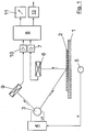
- Measuring field 2 of a given size located on a printing material 1 is of a as a light bulb 3 designed lighting device via a Illuminated optics shown with radiation.
- the light bulb 3 of the The lighting device is controlled by an associated controller 4 with the provided operating voltage U and the corresponding operating current I operated.
- the controller 4 of the lamp 3 of the lighting device is also available a signal transmitter 5 detecting the printing speed v in signal connection.
- the controller 4 is preferably a programmable one Control, where in a memory of this control 4 to be tabulated Speed ranges of the relative speed v or in the form of a stored functional relationship (characteristic curve) different values values of the operating voltage U / des of the relative speed v Current I for operating the lamp 3 are stored.
- the measuring field 2 moved relative to the measuring system at the speed v light of the lamp 3 remitted on the printing material 1 is turned on photoelectric receiver 6 by optical means, not shown (apertures, Lenses, light guides, etc.).
- photoelectric receiver 6 it can this is, in particular, a spectral receiver, which is the Light in different wavelengths is evaluated selectively and accordingly interrogable signals converts.
- Such photoelectric receivers 6 are spectral reflectance receivers known and therefore require no further explanation.
- the signals of the photoelectric receiver 6 are connected downstream of the latter Amplifier device 7 amplified and the output side to one of the Amplifier device 7 downstream evaluation unit 8 forwarded.
- the lamp 3 is assigned a photoelectric receiver 9 which directly detects its radiation, together with optical means (not shown), by means of which a spectral analysis of the light emitted directly by the lamp 3 takes place.
- the further photoelectric receiver 9 can also be a CCD line sensor or a diode line, which is expanded to a spectral analysis system by connecting a diffraction grating, for example.
- the photoelectric receiver 9 is connected on the output side to an amplifier device 10, the output signal of which is also fed to the evaluation device 8.
- the evaluation device 8 calculates a measured value M ( ⁇ ) related to a predetermined (stored) illuminance (spectral intensity distribution b ( ⁇ )), which can be displayed on a display device 11 downstream of the evaluation device 8.
- the measured value M ( ⁇ ) can also be fed via a transmitter 13 to a further processing station (not shown), in which corresponding data for quality control, the derivation of control variables (controllers), etc. can be formed.
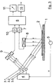
- the measuring device differs from that shown in FIG. 1 Variant in that in the beam path to act on the photoelectric Receiver 9 with the different according to the printing speed v from the lamp 3 emitted light reflecting the light of the lamp 3 White standard 12 (absolute white) is arranged. Also in this embodiment the output signals of the photoelectric receiver 9 over an amplifier unit 10 which emits the light of the photoelectric receiver 6 processing evaluation unit 8 and in the above processed as described. An investigation of one of the following also follows different spectral intensity distributions of the lamp 3 and thus of the printing speed independent measurement value M ( ⁇ ), which on the Display device 11 can be displayed or forwarded via the transmitter 13.
- the further photoelectric Receiver 9 for detecting the output directly from the lamp 3 Light can be a receiver trained in the same way as this for spectral division and photoelectric conversion of the from the measuring surface 2 reflected light is used. It is also possible the further photoelectric receiver 9 as a the light of the lamp 3 in for example two or three different spectral ranges selectively to form the sensing sensor system and on the basis of the thus obtained Measured values the spectral intensity distribution of the light on the basis of interpolation algorithms. This is especially the case with one continuous spectrum light from incandescent lamps in a simple manner possible.
- the lighting device has A total of three lamps that can be switched individually via the controller 3.1, 3.2, 3.3. These lamps 3.1, 3.2, 3.3 are in the power different and coordinated.
- Lamp 3.2 preferably has the double the power of lamp 3.1 and lamp 3.3 in turn double the power from lamp 3.2 on. By switching one or more individually or in combination the lamps 3.1, 3.2, 3.3 it is designed in such a way Lighting device possible, a power range that is seven times corresponds to the performance of lamp 3.1.
- At least one of the lamps 3.1, 3.2, 3.3 at least in one To control part of the performance range continuously or in performance levels, see above that there is a continuous or quasi-continuous adaptation of the Illumination power corresponding to the respective relative speed v results.
Landscapes
- Physics & Mathematics (AREA)
- General Health & Medical Sciences (AREA)
- Immunology (AREA)
- Health & Medical Sciences (AREA)
- Life Sciences & Earth Sciences (AREA)
- Chemical & Material Sciences (AREA)
- Analytical Chemistry (AREA)
- Biochemistry (AREA)
- Engineering & Computer Science (AREA)
- General Physics & Mathematics (AREA)
- Pathology (AREA)
- Textile Engineering (AREA)
- Mathematical Physics (AREA)
- Theoretical Computer Science (AREA)
- Spectroscopy & Molecular Physics (AREA)
- Spectrometry And Color Measurement (AREA)
- Photometry And Measurement Of Optical Pulse Characteristics (AREA)
- Recording Measured Values (AREA)
Applications Claiming Priority (2)
| Application Number | Priority Date | Filing Date | Title |
|---|---|---|---|
| DE19628303 | 1996-07-13 | ||
| DE19628303A DE19628303C2 (de) | 1996-07-13 | 1996-07-13 | Verfahren und Vorrichtung zur Erfassung spektraler Remissionen |
Publications (3)
| Publication Number | Publication Date |
|---|---|
| EP0818675A2 true EP0818675A2 (fr) | 1998-01-14 |
| EP0818675A3 EP0818675A3 (fr) | 1998-04-15 |
| EP0818675B1 EP0818675B1 (fr) | 2003-04-09 |
Family
ID=7799751
Family Applications (1)
| Application Number | Title | Priority Date | Filing Date |
|---|---|---|---|
| EP97110961A Expired - Lifetime EP0818675B1 (fr) | 1996-07-13 | 1997-07-02 | Méthode et dispositif de mesure de remission spectrale |
Country Status (5)
| Country | Link |
|---|---|
| US (1) | US5973789A (fr) |
| EP (1) | EP0818675B1 (fr) |
| JP (1) | JPH1073485A (fr) |
| AT (1) | ATE237130T1 (fr) |
| DE (2) | DE19628303C2 (fr) |
Cited By (3)
| Publication number | Priority date | Publication date | Assignee | Title |
|---|---|---|---|---|
| DE19920184A1 (de) * | 1999-05-03 | 2000-11-30 | Optosens Optische Spektroskopi | Verfahren für die gleichzeitige Erfassung von diffuser und specularer Reflexion von Proben, insbesondere undurchsichtiger Proben, sowie Reflektanz-Meßsonde |
| WO2001065218A1 (fr) * | 2000-03-02 | 2001-09-07 | Ndc Infrared Engineering Limited | Dispositif de detection electromagnetique |
| WO2015036565A3 (fr) * | 2013-09-12 | 2015-06-11 | Windmöller & Hölscher Kg | Capteur de détection optique de marquages sur une bande continue de matériau en mouvement |
Families Citing this family (7)
| Publication number | Priority date | Publication date | Assignee | Title |
|---|---|---|---|---|
| DE19837084B4 (de) * | 1998-08-17 | 2009-10-08 | Volkswagen Ag | Verfahren zur optischen Erkennung von Schweißnähten zwischen einer Radschüssel und einer Radfelge eines Kfz-Rades |
| TW430738B (en) * | 2000-05-22 | 2001-04-21 | Acer Peripherals Inc | A detection device to detect the light emitted from a planar light source |
| FR2827043B1 (fr) * | 2001-07-05 | 2004-02-27 | I2S | Procede de numerisation d'une surface defilant a haute vitesse |
| US7251065B2 (en) * | 2002-01-31 | 2007-07-31 | Eastman Kodak Company | Image color balance for scanners using an illumination spectral sensor |
| DE102004064309B3 (de) | 2004-05-03 | 2022-02-10 | Heidelberger Druckmaschinen Ag | Inline-Messung und Regelung bei Druckmaschinen |
| FR2881373B1 (fr) * | 2005-02-01 | 2008-08-22 | Centre Nat Rech Scient | Systeme de detection pour impression offset et machine utilisant ce systeme |
| JP2020036148A (ja) * | 2018-08-29 | 2020-03-05 | 京セラドキュメントソリューションズ株式会社 | 画像読取装置および画像形成装置 |
Family Cites Families (8)
| Publication number | Priority date | Publication date | Assignee | Title |
|---|---|---|---|---|
| US3892492A (en) * | 1972-10-16 | 1975-07-01 | Loepfe Ag Geb | Optoelectrical apparatus with directional light sources for detecting reflection behaviour of an object |
| DD219730A1 (de) * | 1983-11-14 | 1985-03-13 | Polygraph Leipzig | Verfahren zur messung der farbdichte an einer laufenden druckmaschine |
| JPS62139543A (ja) * | 1985-12-13 | 1987-06-23 | Minolta Camera Co Ltd | 複写機 |
| JP3044713B2 (ja) * | 1989-01-12 | 2000-05-22 | 株式会社小森コーポレーション | 印刷物の品質検査装置及びその方 |
| US4977417A (en) * | 1989-12-14 | 1990-12-11 | Victor Company Of Japan, Ltd. | Electrophotography system |
| JPH03202731A (ja) * | 1989-12-28 | 1991-09-04 | Minolta Camera Co Ltd | 色彩計 |
| DE4013422C2 (de) * | 1990-04-26 | 2000-02-03 | Roland Man Druckmasch | Beleuchtungseinrichtung für ein Dreibereichs-Farbmeßgerät |
| DE4321177A1 (de) * | 1993-06-25 | 1995-01-05 | Heidelberger Druckmasch Ag | Vorrichtung zur parallelen Bildinspektion und Farbregelung an einem Druckprodukt |
-
1996
- 1996-07-13 DE DE19628303A patent/DE19628303C2/de not_active Expired - Fee Related
-
1997
- 1997-07-02 AT AT97110961T patent/ATE237130T1/de not_active IP Right Cessation
- 1997-07-02 EP EP97110961A patent/EP0818675B1/fr not_active Expired - Lifetime
- 1997-07-02 DE DE59709746T patent/DE59709746D1/de not_active Expired - Fee Related
- 1997-07-11 US US08/891,375 patent/US5973789A/en not_active Expired - Fee Related
- 1997-07-14 JP JP9187947A patent/JPH1073485A/ja active Pending
Cited By (5)
| Publication number | Priority date | Publication date | Assignee | Title |
|---|---|---|---|---|
| DE19920184A1 (de) * | 1999-05-03 | 2000-11-30 | Optosens Optische Spektroskopi | Verfahren für die gleichzeitige Erfassung von diffuser und specularer Reflexion von Proben, insbesondere undurchsichtiger Proben, sowie Reflektanz-Meßsonde |
| DE19920184C2 (de) * | 1999-05-03 | 2001-06-07 | Optosens Optische Spektroskopi | Verfahren für die gleichzeitige Erfassung von diffuser und specularer Reflexion von Proben, insbesondere undurchsichtiger Proben, sowie Reflektanz-Meßsonde |
| WO2001065218A1 (fr) * | 2000-03-02 | 2001-09-07 | Ndc Infrared Engineering Limited | Dispositif de detection electromagnetique |
| US6875985B2 (en) | 2000-03-02 | 2005-04-05 | Ndc Infrared Engineering Limited | Electomagnetic detection apparatus |
| WO2015036565A3 (fr) * | 2013-09-12 | 2015-06-11 | Windmöller & Hölscher Kg | Capteur de détection optique de marquages sur une bande continue de matériau en mouvement |
Also Published As
| Publication number | Publication date |
|---|---|
| EP0818675B1 (fr) | 2003-04-09 |
| DE19628303A1 (de) | 1998-01-22 |
| DE19628303C2 (de) | 1998-05-07 |
| DE59709746D1 (de) | 2003-05-15 |
| EP0818675A3 (fr) | 1998-04-15 |
| ATE237130T1 (de) | 2003-04-15 |
| US5973789A (en) | 1999-10-26 |
| JPH1073485A (ja) | 1998-03-17 |
Similar Documents
| Publication | Publication Date | Title |
|---|---|---|
| EP1314972B1 (fr) | Spectrophotomètre et son utilisation | |
| DE19617009C2 (de) | Photoelektrische Meßeinrichtung | |
| EP1694049B1 (fr) | Colorimètre et tête de mesure associée | |
| DE3586961T2 (de) | Farbensensor. | |
| EP1805979B1 (fr) | Procede de correction de valeurs mesurees d'images | |
| EP0884180B1 (fr) | Procédé de commande ou de regulation des operations effectuées par une machine d'impression | |
| EP0824736A1 (fr) | Dispositif et procede pour le controle d'objets sous forme de feuilles tels que des billets de banque ou des titres | |
| EP0818675B1 (fr) | Méthode et dispositif de mesure de remission spectrale | |
| EP1775565A1 (fr) | Procédé de mesure de couleur d'échantillons imprimés comprennant des azurants optiques | |
| EP1470918A2 (fr) | Système et méthode de mesure de couleurs dans une machine à imprimer | |
| DE102014103640A1 (de) | Vorrichtung und Verfahren zum Untersuchen von Oberflächeneigenschaften | |
| EP2985579A1 (fr) | Spectrometre dote d'un monochromateur et un filtre de tri sequentiel | |
| DE3854020T2 (de) | Verfahren zur Untersuchung von Blättern mit gleichzeitiger Auslösung der Messbereiche und der spektralen Bänder. | |
| DE69416098T2 (de) | Verfahren und Vorrichtung zur Kennzeichnung und Unterscheidung von legalen Banknoten und Dokumenten | |
| EP0505769B1 (fr) | Procédé de détermination du recouvrement de la surface d'un modèle, particulièrement une plaque, et dispositif pour exécuter ce procédé | |
| DE3244286A1 (de) | Elektro-optische vorrichtung zum erkennen von farben | |
| DE102004058408B4 (de) | Vorrichtung zur Bestimmung von Oberflächeneigenschaften | |
| DE69005681T2 (de) | Transmissions-/Reflektionsdensitometer mit zwei Messköpfen. | |
| DE102005024271B4 (de) | Gitterspektrometersystem und Verfahren zur Messwerterfassung | |
| EP2034286B1 (fr) | Méthode de contrôle d'un processus d'impression utilisant un système de mesure spectral comprenant un modulateur spatial de lumière | |
| DE10356729B4 (de) | Farbsensor | |
| DE4439533C2 (de) | Vorrichtung und Verfahren zur farbmetrischen Erfassung von Farbkontrollfeldern bei der Farbkalibrierung der ausgegebenen Farben von elektronischen Bildverarbeitungssystemen | |
| CH690864A5 (de) | Gerät und Verfahren zur Farbmessung und/oder Farberkennung sowie Vorrichtung in einem solchen Gerät. | |
| DE19927452C2 (de) | Vorrichtung zur Messung von Feuchtigkeit und Reflexionsvermögen von Oberflächen | |
| DE19542239C2 (de) | Verfahren und Vorrichtung zur bereichsweisen Messung der Durchlässigkeit einer fotografischen Farbkopiervorlage |
Legal Events
| Date | Code | Title | Description |
|---|---|---|---|
| PUAI | Public reference made under article 153(3) epc to a published international application that has entered the european phase |
Free format text: ORIGINAL CODE: 0009012 |
|
| AK | Designated contracting states |
Kind code of ref document: A2 Designated state(s): AT CH DE FR GB IT LI NL SE |
|
| PUAL | Search report despatched |
Free format text: ORIGINAL CODE: 0009013 |
|
| AK | Designated contracting states |
Kind code of ref document: A3 Designated state(s): AT BE CH DE DK ES FI FR GB GR IE IT LI LU MC NL PT SE |
|
| 17P | Request for examination filed |
Effective date: 19980325 |
|
| AKX | Designation fees paid |
Free format text: AT CH DE FR GB IT LI NL SE |
|
| RBV | Designated contracting states (corrected) |
Designated state(s): AT CH DE FR GB IT LI NL SE |
|
| 17Q | First examination report despatched |
Effective date: 20011022 |
|
| GRAH | Despatch of communication of intention to grant a patent |
Free format text: ORIGINAL CODE: EPIDOS IGRA |
|
| GRAH | Despatch of communication of intention to grant a patent |
Free format text: ORIGINAL CODE: EPIDOS IGRA |
|
| GRAA | (expected) grant |
Free format text: ORIGINAL CODE: 0009210 |
|
| AK | Designated contracting states |
Designated state(s): AT CH DE FR GB IT LI NL SE |
|
| PG25 | Lapsed in a contracting state [announced via postgrant information from national office to epo] |
Ref country code: NL Free format text: LAPSE BECAUSE OF FAILURE TO SUBMIT A TRANSLATION OF THE DESCRIPTION OR TO PAY THE FEE WITHIN THE PRESCRIBED TIME-LIMIT Effective date: 20030409 Ref country code: IT Free format text: LAPSE BECAUSE OF FAILURE TO SUBMIT A TRANSLATION OF THE DESCRIPTION OR TO PAY THE FEE WITHIN THE PRESCRIBED TIME-LIMIT;WARNING: LAPSES OF ITALIAN PATENTS WITH EFFECTIVE DATE BEFORE 2007 MAY HAVE OCCURRED AT ANY TIME BEFORE 2007. THE CORRECT EFFECTIVE DATE MAY BE DIFFERENT FROM THE ONE RECORDED. Effective date: 20030409 |
|
| REG | Reference to a national code |
Ref country code: GB Ref legal event code: FG4D Free format text: NOT ENGLISH |
|
| REG | Reference to a national code |
Ref country code: CH Ref legal event code: EP |
|
| GBT | Gb: translation of ep patent filed (gb section 77(6)(a)/1977) |
Effective date: 20030409 |
|
| REG | Reference to a national code |
Ref country code: CH Ref legal event code: NV Representative=s name: E. BLUM & CO. PATENTANWAELTE |
|
| PG25 | Lapsed in a contracting state [announced via postgrant information from national office to epo] |
Ref country code: SE Free format text: LAPSE BECAUSE OF FAILURE TO SUBMIT A TRANSLATION OF THE DESCRIPTION OR TO PAY THE FEE WITHIN THE PRESCRIBED TIME-LIMIT Effective date: 20030709 |
|
| NLV1 | Nl: lapsed or annulled due to failure to fulfill the requirements of art. 29p and 29m of the patents act | ||
| ET | Fr: translation filed | ||
| PLBE | No opposition filed within time limit |
Free format text: ORIGINAL CODE: 0009261 |
|
| STAA | Information on the status of an ep patent application or granted ep patent |
Free format text: STATUS: NO OPPOSITION FILED WITHIN TIME LIMIT |
|
| 26N | No opposition filed |
Effective date: 20040112 |
|
| PGFP | Annual fee paid to national office [announced via postgrant information from national office to epo] |
Ref country code: GB Payment date: 20050621 Year of fee payment: 9 |
|
| PGFP | Annual fee paid to national office [announced via postgrant information from national office to epo] |
Ref country code: AT Payment date: 20050628 Year of fee payment: 9 |
|
| PGFP | Annual fee paid to national office [announced via postgrant information from national office to epo] |
Ref country code: FR Payment date: 20050712 Year of fee payment: 9 |
|
| PG25 | Lapsed in a contracting state [announced via postgrant information from national office to epo] |
Ref country code: GB Free format text: LAPSE BECAUSE OF NON-PAYMENT OF DUE FEES Effective date: 20060702 Ref country code: AT Free format text: LAPSE BECAUSE OF NON-PAYMENT OF DUE FEES Effective date: 20060702 |
|
| GBPC | Gb: european patent ceased through non-payment of renewal fee |
Effective date: 20060702 |
|
| REG | Reference to a national code |
Ref country code: FR Ref legal event code: ST Effective date: 20070330 |
|
| REG | Reference to a national code |
Ref country code: CH Ref legal event code: PFA Owner name: MAN ROLAND DRUCKMASCHINEN AG Free format text: MAN ROLAND DRUCKMASCHINEN AG#MUEHLHEIMER STRASSE 341#63075 OFFENBACH (DE) -TRANSFER TO- MAN ROLAND DRUCKMASCHINEN AG#MUEHLHEIMER STRASSE 341#63075 OFFENBACH (DE) |
|
| PG25 | Lapsed in a contracting state [announced via postgrant information from national office to epo] |
Ref country code: FR Free format text: LAPSE BECAUSE OF NON-PAYMENT OF DUE FEES Effective date: 20060731 |
|
| REG | Reference to a national code |
Ref country code: CH Ref legal event code: PFA Owner name: MANROLAND AG Free format text: MAN ROLAND DRUCKMASCHINEN AG#MUEHLHEIMER STRASSE 341#63075 OFFENBACH (DE) -TRANSFER TO- MANROLAND AG#MUEHLHEIMER STRASSE 341#63075 OFFENBACH (DE) |
|
| PGFP | Annual fee paid to national office [announced via postgrant information from national office to epo] |
Ref country code: DE Payment date: 20090722 Year of fee payment: 13 Ref country code: CH Payment date: 20090715 Year of fee payment: 13 |
|
| REG | Reference to a national code |
Ref country code: CH Ref legal event code: PL |
|
| PG25 | Lapsed in a contracting state [announced via postgrant information from national office to epo] |
Ref country code: CH Free format text: LAPSE BECAUSE OF NON-PAYMENT OF DUE FEES Effective date: 20100731 Ref country code: DE Free format text: LAPSE BECAUSE OF NON-PAYMENT OF DUE FEES Effective date: 20110201 Ref country code: LI Free format text: LAPSE BECAUSE OF NON-PAYMENT OF DUE FEES Effective date: 20100731 |
|
| REG | Reference to a national code |
Ref country code: DE Ref legal event code: R119 Ref document number: 59709746 Country of ref document: DE Effective date: 20110201 |