EP1775565A1 - Procédé de mesure de couleur d'échantillons imprimés comprennant des azurants optiques - Google Patents
Procédé de mesure de couleur d'échantillons imprimés comprennant des azurants optiques Download PDFInfo
- Publication number
- EP1775565A1 EP1775565A1 EP05022584A EP05022584A EP1775565A1 EP 1775565 A1 EP1775565 A1 EP 1775565A1 EP 05022584 A EP05022584 A EP 05022584A EP 05022584 A EP05022584 A EP 05022584A EP 1775565 A1 EP1775565 A1 EP 1775565A1
- Authority
- EP
- European Patent Office
- Prior art keywords
- light
- measurement
- sample
- reflection factor
- corrected
- Prior art date
- Legal status (The legal status is an assumption and is not a legal conclusion. Google has not performed a legal analysis and makes no representation as to the accuracy of the status listed.)
- Granted
Links
Images


Classifications
-
- G—PHYSICS
- G01—MEASURING; TESTING
- G01J—MEASUREMENT OF INTENSITY, VELOCITY, SPECTRAL CONTENT, POLARISATION, PHASE OR PULSE CHARACTERISTICS OF INFRARED, VISIBLE OR ULTRAVIOLET LIGHT; COLORIMETRY; RADIATION PYROMETRY
- G01J3/00—Spectrometry; Spectrophotometry; Monochromators; Measuring colours
- G01J3/02—Details
- G01J3/10—Arrangements of light sources specially adapted for spectrometry or colorimetry
-
- G—PHYSICS
- G01—MEASURING; TESTING
- G01J—MEASUREMENT OF INTENSITY, VELOCITY, SPECTRAL CONTENT, POLARISATION, PHASE OR PULSE CHARACTERISTICS OF INFRARED, VISIBLE OR ULTRAVIOLET LIGHT; COLORIMETRY; RADIATION PYROMETRY
- G01J3/00—Spectrometry; Spectrophotometry; Monochromators; Measuring colours
- G01J3/46—Measurement of colour; Colour measuring devices, e.g. colorimeters
- G01J3/50—Measurement of colour; Colour measuring devices, e.g. colorimeters using electric radiation detectors
-
- G—PHYSICS
- G01—MEASURING; TESTING
- G01J—MEASUREMENT OF INTENSITY, VELOCITY, SPECTRAL CONTENT, POLARISATION, PHASE OR PULSE CHARACTERISTICS OF INFRARED, VISIBLE OR ULTRAVIOLET LIGHT; COLORIMETRY; RADIATION PYROMETRY
- G01J3/00—Spectrometry; Spectrophotometry; Monochromators; Measuring colours
- G01J3/46—Measurement of colour; Colour measuring devices, e.g. colorimeters
- G01J3/52—Measurement of colour; Colour measuring devices, e.g. colorimeters using colour charts
- G01J3/524—Calibration of colorimeters
-
- G—PHYSICS
- G01—MEASURING; TESTING
- G01N—INVESTIGATING OR ANALYSING MATERIALS BY DETERMINING THEIR CHEMICAL OR PHYSICAL PROPERTIES
- G01N21/00—Investigating or analysing materials by the use of optical means, i.e. using sub-millimetre waves, infrared, visible or ultraviolet light
- G01N21/17—Systems in which incident light is modified in accordance with the properties of the material investigated
- G01N21/25—Colour; Spectral properties, i.e. comparison of effect of material on the light at two or more different wavelengths or wavelength bands
- G01N21/255—Details, e.g. use of specially adapted sources, lighting or optical systems
-
- G—PHYSICS
- G01—MEASURING; TESTING
- G01J—MEASUREMENT OF INTENSITY, VELOCITY, SPECTRAL CONTENT, POLARISATION, PHASE OR PULSE CHARACTERISTICS OF INFRARED, VISIBLE OR ULTRAVIOLET LIGHT; COLORIMETRY; RADIATION PYROMETRY
- G01J3/00—Spectrometry; Spectrophotometry; Monochromators; Measuring colours
- G01J3/12—Generating the spectrum; Monochromators
- G01J2003/1213—Filters in general, e.g. dichroic, band
-
- G—PHYSICS
- G01—MEASURING; TESTING
- G01J—MEASUREMENT OF INTENSITY, VELOCITY, SPECTRAL CONTENT, POLARISATION, PHASE OR PULSE CHARACTERISTICS OF INFRARED, VISIBLE OR ULTRAVIOLET LIGHT; COLORIMETRY; RADIATION PYROMETRY
- G01J3/00—Spectrometry; Spectrophotometry; Monochromators; Measuring colours
- G01J3/46—Measurement of colour; Colour measuring devices, e.g. colorimeters
- G01J2003/468—Measurement of colour; Colour measuring devices, e.g. colorimeters of objects containing fluorescent agent
Definitions
- the invention relates to a method for color measurement of samples printed on substrates with brighteners according to the preamble of independent claim 1.
- Optical brighteners can improve the whiteness of the paper (generally substrate) and reduce manufacturing costs.
- Optical brighteners absorb light in the ultraviolet (UV) wavelength range of 320 to 410 nm and re-emit fluorescent light in the visible blue spectral range between 420 and 550 nm.
- UV ultraviolet
- the maximum of the fluorescence spectrum is between 430 and 440 nm.
- optical brighteners and the produced color of the paper are strongly influenced by the spectral distribution of the illumination light, above all by the ratio of the light levels in the UV and in the blue spectral range.
- the color reproduction of printed samples is additionally influenced by the absorption behavior of the ink layer on the paper substrate.
- the non-linear behavior of optical brighteners places high demands on color measurement technology.
- the objectives of color measurement technology are to obtain measured values that correlate well with a specific visual observation condition with a defined illumination spectrum.
- the illumination spectra in the devices have identical relative distribution in the UV and blue spectral regions. Especially in the UV range, there are major differences between the various measuring devices.
- a bi-spectral measuring device has a monochromator in the illumination optics and a spectral analyzer in the receiver channel. The measurement is done sequentially. For each illumination wavelength, a complete reflection spectrum is measured and stored in matrix form. By multiplying the matrix with a vector which has the spectral optical energy distribution of the required type of light, the resulting reflection spectrum of the sample is determined.
- This measurement technique includes no limitation; however, the sequential measurement process is time-consuming. The measuring technology is expensive to implement, so that it is out of the question for industrial use.
- the devices BFC-450 of the company Labsphere and CM-3800 of the company Minolta are mentioned.
- the U.S. Patent No. 6844931 describes a color measuring system with variable light emitting diode (LED) illumination and a spectral analyzer in the receiver.
- the LED light source consists of a large number of differently colored, white and UV LEDs.
- the individual LEDs can be individually controlled so that the spectral illumination distribution can be adapted to a desired spectrum electronically.
- the determination of the spectral reflectance factor of the sample is then carried out with a single measurement with the desired illumination spectrum.
- the present invention is intended to provide a method for the color measurement of brightened specimens, which improves the accuracy of the measured values and at the same time can be implemented simply and cost-effectively in comparison to known measuring methods.
- the method according to the invention determines the spectral reflection factor of the sample with a double measurement and combination of the measured values obtained thereby.
- the spectral reflection factor is determined by the UV blocking filter technique known per se.
- the second measurement only UV light is illuminated and the fluorescence spectrum is measured separately. The fluorescence spectrum is then weighted with spectrally dependent correction factors and added to the spectral reflection factor of the UV cut filter measurement.
- the spectral correction factors are determined during device manufacture for a specific set of light types and stored in the device.
- the measuring method can also be realized with two different light sources with different emission spectrum, for example by the combination of a UV LED and a white LED.
- the measurement method also makes sense for use in an automated color measurement system for calibrating printed color charts (color charts) for calibrating printers. Based on the double measurement data, color profiles for different types of light can be generated with a color management software.
- the presence of illumination only in the UV range also allows the measurement of printed security features generated by excitation in the UV range.
- various measuring arrangements are known to be used: diffuse measuring geometries with integrating sphere, 45 ° / 0 ° measuring geometry and goniometric measuring methods with more than one measuring angle.
- the measuring arrangements are defined in various standards or recommendations, for example in the publication CIE 15 of the Commission International d'Eclairage and in the standard DIN 5033 Part 7.
- the measuring device shown in FIG. 1 and suitable for the measuring method according to the invention is based on principle Construction on the known measuring geometries.
- the measuring device comprises a first light source 1, a first illumination optical system 2, a first pick-up optical system 3, a first photoelectric converter 4, a second light source 5, a second illumination optical system 6, a UV filter 7, a second pick-up optical system 8, a second photoelectric converter 9, a lamp controller 10 and a computer R for controlling the photoelectric converters and for digitizing and further processing or storing the measurement signals generated by the photoelectric converters.
- the first light source 1, first illumination optics 2, first pick-up optics 3 and the first transducer 4 together form a first measurement arrangement known per se, which illuminates a measurement object M or a sample at an incident angle of 45 ° and subtracts the measurement light remitted from the measurement object Drop angle of 0 ° fields.
- the second light source 5, the second illumination optics 6, the UV filter 7, the second pick-up optics 8 and the second transducer 9 form a second, likewise known measuring arrangement with a symmetrical measuring geometry, wherein the angle of incidence of the illumination and the angle of reflection of the remitted Measuring light, for example, each 30 °.
- the measuring method according to the invention is explained below purely by way of example with reference to the measuring configuration of FIG. However, it is adaptable to all other common measuring arrangements.
- the first light source 1 typically a light source is used, which has a continuous emission spectrum over the UV and visible spectral range.
- a light source for example, xenon arc lamps or incandescent lamps can be used.
- the first photoelectric converter 4 is preferably designed as a spectral analyzer, which is sensitive at minimum over the visible spectral range of 400 to 700 nm.
- the spectral analyzer can be designed in a conventional manner as a spectrometer or colorimeter.
- the first measuring arrangement fulfills the geometric measuring conditions of the normalized 45 ° / 0 ° geometry.
- two measurements are carried out, once under illumination of the test object M with light without UV component and once under illumination only with UV light, whereby the sequence of the two measurements does not matter ,
- an adjustable filter arrangement 12 which, depending on the setting, is transparent either only to visible light or only to UV light.
- the filter arrangement can be implemented, for example, by a filter wheel with two matching filters, as already used in the aforementioned known device "SpectroEye".
- One of the two filters 12a of the filter arrangement 12 is a UV blocking filter, which is designed as an edge filter which suppresses illumination light below 400 nm and has good transmission over the visible range.
- the other filter 12b of the filter arrangement 12 is a complementary edge filter which suppresses the light with a wavelength above 400 nm and is as transparent as possible for UV light.
- This filter (UV transmission filter) can also be designed so that it allows a better adaptation of the illumination spectrum in the UV range to a desired reference light. For the double measurement is, as already said, first with UV blocking filter and then measured with UV transmission filter or vice versa.
- a suitable switchable UV / non-UV double illumination can, according to a second variant, alternatively also take place by means of two or more different light sources, which can be switched on and off individually. Some of the light sources may only emit light in the UV range, the other part of the light sources only in the visible range. This can be realized by using continuous light sources with fixed filters. Alternatively, light sources can be used which have a spectrally limited emission spectrum without additional filtering. Typical light sources of this type are light-emitting diodes (LEDs).
- LEDs light-emitting diodes
- As UV light source for example, the UV LEDs NCCU033 (T) and NCCU001E manufacturer Nichia with peak wavelengths of 365 nm, respectively. 380 nm individually or in combination.
- the UV blocking filter characteristic can be realized, for example, with white LEDs, such as those sold by the manufacturer Lumileds under the product name Luxeon. These white LEDs have a continuous emission spectrum in the range of 420 nm to 700 nm. In FIG. 1, this implementation possibility for a double illumination with controlled light sources is symbolized by the involvement of the second measuring arrangement 5-9. The filter assembly 12 is of course unnecessary then.
- the illumination and measurement with UV light need not comply with the 45 ° / 0 ° standard geometry, the measuring light can be applied at any angle to the measurement object. Therefore, if separate light sources are used for the UV light and the visible light, it is possible to arrange the UV light sources at a smaller angle than 45 °, e.g. about 30 °, which often allows a more compact design of the measuring device can be achieved.
- the measuring device further has a white reference standard W, which is calibrated for the absolute reflection factor.
- the white reference standard can consist of a white ceramic tile, which is provided with a calibrated reference spectrophotometer has been calibrated. In measurements on the white reference standard W, this (in a manner known per se) takes the place of the actual measurement object M.
- the measuring device has a UV reference channel for the UV light source, which serves to monitor the light level of the UV light source over the life of the device and to detect level fluctuations.
- the level fluctuations are taken into account by the measuring system during the measured value calculation.
- the UV reference channel can be realized with the spectral photoelectric converter 4, if this is sensitive in the UV range and the white reference standard W has a sufficient reflection factor in the UV range.
- the UV reference channel can be realized with a photodiode (transducer 9) which is sensitive in the UV range and measures the light reflected by the white reference standard.
- a third possibility for the realization of the UV reference channel is the incorporation of a fluorescent sample, which is excited in the UV range and generates light in the visible range. The visible fluorescence component can then be measured with the spectral receiver (transducer 4). Suitable fluorescence standards are offered, for example, by Labsphere under the product name Spectralon.
- the receiver channel (formed by the pick-up optics and the spectral converter) must be radiometrically calibrated.
- the radiometric calibration is performed by measuring with the receiver channel a continuous light source with known spectral signal distribution (reference spectrum).
- the radiometric calibration is formed in a manner known per se by the quotient of the reference spectrum by the corresponding digitized (spectral) measured values of the receiver.
- the correction factors required for the measurement method according to the invention for the combination of the fluorescence spectrum and the UV rejection filter reflection spectrum are determined during the device calibration.
- a set of brightened color samples color samples printed on a brightener-containing substrate
- the sample set includes at least one type of substrate or paper with optical brighteners typical for the application.
- the measured reference reflection spectra are determined and stored for the desired types of light over the visible range.
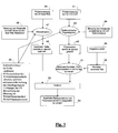
- the fluorescence spectrum of each (calibration) sample is measured with UV illumination (block 21) and converted into energy units via the radiometric calibration of the spectral receiver (block 22) and stored (block 23).
- the radiometric calibration is stored in the calibration data of the device (block 20).
- the UV illumination is performed at the same light level as the white reference measurement (block 24).
- the light level is regulated by the control electronics 10.
- the spectral reflection factor of the sample is measured in the UV blocking filter mode (illumination only with visible light) in a manner known per se.
- the measured values (block 25) are transformed into absolute units of the spectral reflection factor via the comparison with the reference white measurement (block 26) and the calibration data of the white reference standard (block 27).
- the resulting spectral reflection factors are stored (block 28).
- the fluorescence spectrum (block 23) is then corrected by means of a correction model (block 29), and the measurement spectra are formed from the sum of the spectral reflection factor in the UV cut filter mode with the corrected fluorescence spectrum (block 30).
- the fluorescence spectrum correction model includes spectrally dependent scaling factors that adjust the relative distribution of the fluorescence spectrum.
- the spectral scaling factors include a variable for each spectral reading in the range of 420 nm to 550 nm.
- the absolute level is additionally adjusted with a global scaling factor.
- the scaling factors are also referred to below as correction parameters (for the correction model).
- the scaling factors are calculated by means of a compensation calculation known per se (block 34) on the basis of the previously determined corrected spectral reflection factor with fluorescence component for the selected light type (block 32) and the reference spectrum for the same light type (block 33), the scaling factors being the ones to be determined Variables of the adjustment calculation are.
- the compensation calculation is carried out in a manner known per se such that the differences between the measurement spectra (block 32) and the reference spectra (block 33) are minimized (for example minimal quadratic deviation).
- the result of the compensation calculation then supplies the variables or scaling factors as a correction parameter set for the relevant type of light (block 35).
- the correction parameter sets for the individual types of light are then stored in the calibration data of the device for use in the inventive measuring method (block 20).
- correction parameters and dependencies can be introduced into the correction model. It may, for example, be an additional dependency of Correction factors are introduced as a function of the spectral reflection factor of the sample.
- the reflected light level of the UV light source is first determined (block 44). Then, the spectral measurement values for the white reference standard are measured with the UV cutoff filter measurement channel (block 46).
- sample measurements can be performed. These measurements are carried out as a double measurement with UV cut filter (block 45) and only with UV light (block 41). Both measurements are carried out with the same light level as in the white measurement. The light levels are kept constant by the control electronics 10.
- the sample measurement with UV cut filter is transformed via a white balance (block 47) into absolute reflection spectra (block 48).
- the white balance is accomplished by multiplying the sample readings in UV cutoff filter mode by the quotient of the spectral reflectance factor in the instrument's calibration data (block 20) and the white measurement (block 46).
- the sample measurement without UV light is converted via a radiometric level adjustment (block 42) into a radiometric fluorescence spectrum (block 43).
- the radiometric level adjustment involves multiplying the sample measurement without UV light (block 41) by the radiometric calibration in the calibration data in the instrument (block 20).
- the light level is corrected by multiplying the fluorescence spectrum by the quotient of the light level of the white measurement (block 44) and the light level in the calibration data (block 20).
- a desired light type can be selected (block 49).
- the corresponding set of correction parameters is loaded from the calibration data in the device (block 20) (block 50).
- the correction parameter set is applied to the absolute fluorescence spectra in the correction model (block 51).
- the spectral reflection factor in the UV cut-off filter mode (block 48) and the corrected fluorescence spectrum (block 51) are added (block 52) and transformed into the reflection spectrum with the defined fluorescence fraction for the desired light type (block 53).
- the equivalent spectral reflection factors for the desired light types can now be determined and displayed for each sample measurement.
- the reflection spectra determined in this way can be evaluated colorimetrically in a known manner, e.g. for calculating color values. Furthermore, it is possible to calculate quality parameters for the color reproduction of the sample, such as a metamerism index or color inconstancy index, for different types of light, using only a single double measurement in a manner known per se.
Landscapes
- Physics & Mathematics (AREA)
- Spectroscopy & Molecular Physics (AREA)
- General Physics & Mathematics (AREA)
- Analytical Chemistry (AREA)
- Life Sciences & Earth Sciences (AREA)
- Chemical & Material Sciences (AREA)
- Health & Medical Sciences (AREA)
- Biochemistry (AREA)
- General Health & Medical Sciences (AREA)
- Immunology (AREA)
- Pathology (AREA)
- Spectrometry And Color Measurement (AREA)
- Investigating, Analyzing Materials By Fluorescence Or Luminescence (AREA)
Priority Applications (3)
| Application Number | Priority Date | Filing Date | Title |
|---|---|---|---|
| EP05022584A EP1775565B1 (fr) | 2005-10-17 | 2005-10-17 | Procédé de mesure de couleur d'échantillons imprimés comprenant des azurants optiques |
| DE502005004038T DE502005004038D1 (de) | 2005-10-17 | 2005-10-17 | Verfahren zur Farbmessung von gedruckten Proben mit Aufhellern |
| US11/581,027 US7466417B2 (en) | 2005-10-17 | 2006-10-13 | Process for the colour measurement of printed samples including brighteners |
Applications Claiming Priority (1)
| Application Number | Priority Date | Filing Date | Title |
|---|---|---|---|
| EP05022584A EP1775565B1 (fr) | 2005-10-17 | 2005-10-17 | Procédé de mesure de couleur d'échantillons imprimés comprenant des azurants optiques |
Publications (2)
| Publication Number | Publication Date |
|---|---|
| EP1775565A1 true EP1775565A1 (fr) | 2007-04-18 |
| EP1775565B1 EP1775565B1 (fr) | 2008-05-07 |
Family
ID=35840029
Family Applications (1)
| Application Number | Title | Priority Date | Filing Date |
|---|---|---|---|
| EP05022584A Expired - Lifetime EP1775565B1 (fr) | 2005-10-17 | 2005-10-17 | Procédé de mesure de couleur d'échantillons imprimés comprenant des azurants optiques |
Country Status (3)
| Country | Link |
|---|---|
| US (1) | US7466417B2 (fr) |
| EP (1) | EP1775565B1 (fr) |
| DE (1) | DE502005004038D1 (fr) |
Cited By (5)
| Publication number | Priority date | Publication date | Assignee | Title |
|---|---|---|---|---|
| EP2003431A1 (fr) | 2007-06-13 | 2008-12-17 | GretagMacbeth AG | Procédé destiné à la mesure de la couleur d'échantillons imprimés avec des matériaux d'éclaircissement |
| DE102008057115A1 (de) * | 2008-11-13 | 2010-05-20 | Lre Medical Gmbh | Verfahren zur quantitativen Bestimmung der Konzentration von Fluorophoren einer Substanz in einer Probe und Vorrichtung zu seiner Durchführung |
| EP2199765A1 (fr) | 2008-12-18 | 2010-06-23 | X-Rite Europe GmbH | Procédé et appareil de mesure de couleur manuelle destinés à la mesure d'une échelle de mesure de couleur |
| DE102007008850B4 (de) * | 2006-03-31 | 2010-10-28 | Axiphos Gmbh | Verfahren zum Bestimmen eines farbmetrischen Wertes, insbesondere eines Weißgrades, einer einen optischen Aufheller enthaltenden Materialoberfläche |
| DE102011111315A1 (de) * | 2011-08-26 | 2013-02-28 | Bundesrepublik Deutschland, vertreten durch das Bundesministerium für Wirtschaft und Technologie, dieses vertreten durch den Präsidenten der Physikalisch-Technischen Bundesanstalt | Verfahren zur Fluoreszenzmessung |
Families Citing this family (21)
| Publication number | Priority date | Publication date | Assignee | Title |
|---|---|---|---|---|
| JP2008145225A (ja) * | 2006-12-08 | 2008-06-26 | Konica Minolta Sensing Inc | 光学特性測定方法及び光学特性測定装置 |
| US7830514B2 (en) * | 2007-10-16 | 2010-11-09 | X-Rite, Inc. | Color measurement systems and methods addressing effects of ultra-violet light |
| JP5239442B2 (ja) * | 2008-03-25 | 2013-07-17 | コニカミノルタオプティクス株式会社 | 蛍光試料の光学特性測定方法および装置 |
| EP2345089A4 (fr) * | 2008-10-17 | 2012-10-03 | Atonometrics Inc | Chambre d exposition à la lumière ultraviolette pour modules photovoltaïques |
| DE102010004417A1 (de) * | 2009-02-09 | 2010-09-02 | Heidelberger Druckmaschinen Ag | Konvertierung von filterlos gemessenen Farbmesswerten in mit Filtern gemessene Farbmesswerte und umgekehrt |
| DE102009019545B4 (de) * | 2009-04-30 | 2018-11-22 | Schattdecor Ag | Verfahren und Vorrichtung zur Durchführung eines optischen Vergleiches zwischen zumindest zwei Mustern, vorzugsweise durch Vergleich von auswählbaren Ausschnitten |
| US8125625B2 (en) * | 2009-07-12 | 2012-02-28 | Hewlett-Packard Development Company, L.P. | Hard copy re-emission color measurement system |
| WO2011052044A1 (fr) * | 2009-10-27 | 2011-05-05 | キヤノン株式会社 | Dispositif de traitement couleurs et procédé de traitement couleurs |
| US8401809B2 (en) | 2010-07-12 | 2013-03-19 | Honeywell International Inc. | System and method for adjusting an on-line appearance sensor system |
| JP5643571B2 (ja) * | 2010-08-18 | 2014-12-17 | キヤノン株式会社 | 蛍光推定装置および蛍光推定方法、および蛍光測定装置 |
| US8807696B2 (en) * | 2012-03-27 | 2014-08-19 | Canon Kabushiki Kaisha | Colorimetric apparatus and colorimetric method |
| US9165223B2 (en) | 2012-06-11 | 2015-10-20 | Ricoh Production Print Solutions LLC | Compensation for optical brighteners of print media to facilitate calibration of a printing system |
| DE102012014263B3 (de) * | 2012-07-19 | 2014-01-16 | Deutsches Zentrum für Luft- und Raumfahrt e.V. | Vorrichtung zur Kalibrierung eines optischenSensors |
| DE102014103640A1 (de) * | 2014-03-17 | 2015-09-17 | Byk-Gardner Gmbh | Vorrichtung und Verfahren zum Untersuchen von Oberflächeneigenschaften |
| US20190049306A1 (en) * | 2017-08-10 | 2019-02-14 | Westco Scientific Instruments, Inc | Calibration for baking contrast units |
| WO2019177583A1 (fr) * | 2018-03-13 | 2019-09-19 | Hewlett-Packard Development Company, L.P. | Étalonnage de système d'impression faisant appel à un dispositif d'impression de référence |
| US20210109016A1 (en) * | 2018-03-13 | 2021-04-15 | Hewlett-Packard Development Company, L.P. | Spectrophotometric measurement estimation |
| CN111750995B (zh) * | 2020-06-04 | 2022-10-14 | 武汉纺织大学 | 一种面向开放测量环境应用的光谱测量方法 |
| JP2022003751A (ja) * | 2020-06-23 | 2022-01-11 | キヤノン株式会社 | 画像処理装置、画像処理装置の制御方法および画像処理システム |
| TWI876231B (zh) * | 2022-11-22 | 2025-03-11 | 財團法人紡織產業綜合研究所 | 布料上色系統及布料上色方法 |
| GB2630290A (en) * | 2023-05-18 | 2024-11-27 | Verivide Ltd | Light sources for colour assessment |
Citations (4)
| Publication number | Priority date | Publication date | Assignee | Title |
|---|---|---|---|---|
| US4699510A (en) * | 1984-11-07 | 1987-10-13 | Measurex Corporation | Color sensor |
| US6020959A (en) * | 1997-10-15 | 2000-02-01 | Minolta Co., Ltd. | Apparatus and method for measuring spectral characteristics of fluorescent sample |
| US20020135768A1 (en) * | 2000-11-06 | 2002-09-26 | Dai Nippon Printing Co., Ltd. | Color measuring method and device for printed matter |
| US20030169421A1 (en) * | 2001-11-26 | 2003-09-11 | Peter Ehbets | Spectrophotometer and its use |
Family Cites Families (1)
| Publication number | Priority date | Publication date | Assignee | Title |
|---|---|---|---|---|
| JP3346095B2 (ja) * | 1995-05-17 | 2002-11-18 | ミノルタ株式会社 | 分光光度計 |
-
2005
- 2005-10-17 DE DE502005004038T patent/DE502005004038D1/de not_active Expired - Lifetime
- 2005-10-17 EP EP05022584A patent/EP1775565B1/fr not_active Expired - Lifetime
-
2006
- 2006-10-13 US US11/581,027 patent/US7466417B2/en active Active
Patent Citations (4)
| Publication number | Priority date | Publication date | Assignee | Title |
|---|---|---|---|---|
| US4699510A (en) * | 1984-11-07 | 1987-10-13 | Measurex Corporation | Color sensor |
| US6020959A (en) * | 1997-10-15 | 2000-02-01 | Minolta Co., Ltd. | Apparatus and method for measuring spectral characteristics of fluorescent sample |
| US20020135768A1 (en) * | 2000-11-06 | 2002-09-26 | Dai Nippon Printing Co., Ltd. | Color measuring method and device for printed matter |
| US20030169421A1 (en) * | 2001-11-26 | 2003-09-11 | Peter Ehbets | Spectrophotometer and its use |
Cited By (8)
| Publication number | Priority date | Publication date | Assignee | Title |
|---|---|---|---|---|
| DE102007008850B4 (de) * | 2006-03-31 | 2010-10-28 | Axiphos Gmbh | Verfahren zum Bestimmen eines farbmetrischen Wertes, insbesondere eines Weißgrades, einer einen optischen Aufheller enthaltenden Materialoberfläche |
| EP2003431A1 (fr) | 2007-06-13 | 2008-12-17 | GretagMacbeth AG | Procédé destiné à la mesure de la couleur d'échantillons imprimés avec des matériaux d'éclaircissement |
| DE102008057115A1 (de) * | 2008-11-13 | 2010-05-20 | Lre Medical Gmbh | Verfahren zur quantitativen Bestimmung der Konzentration von Fluorophoren einer Substanz in einer Probe und Vorrichtung zu seiner Durchführung |
| US8334522B2 (en) | 2008-11-13 | 2012-12-18 | Lre Medical Gmbh | Method for the quantitative determination of the concentration of fluorophores of a substance in a sample and apparatus for carrying out the same |
| DE102008057115B4 (de) * | 2008-11-13 | 2013-11-28 | Lre Medical Gmbh | Verfahren zur quantitativen Bestimmung der Konzentration von Fluorophoren einer Substanz in einer Probe und Vorrichtung zu seiner Durchführung |
| EP2199765A1 (fr) | 2008-12-18 | 2010-06-23 | X-Rite Europe GmbH | Procédé et appareil de mesure de couleur manuelle destinés à la mesure d'une échelle de mesure de couleur |
| DE102011111315A1 (de) * | 2011-08-26 | 2013-02-28 | Bundesrepublik Deutschland, vertreten durch das Bundesministerium für Wirtschaft und Technologie, dieses vertreten durch den Präsidenten der Physikalisch-Technischen Bundesanstalt | Verfahren zur Fluoreszenzmessung |
| WO2013029580A1 (fr) | 2011-08-26 | 2013-03-07 | Bundesrepublik Deutschland, vertreten durch das Bundesministerium für Wirtschaft und Technologie, dieses vertreten durch den Präsidenten der Physikalisch-Technischen Bundesanstalt | Procédé pour la mesure de la fluorescence |
Also Published As
| Publication number | Publication date |
|---|---|
| DE502005004038D1 (de) | 2008-06-19 |
| US7466417B2 (en) | 2008-12-16 |
| US20070086009A1 (en) | 2007-04-19 |
| EP1775565B1 (fr) | 2008-05-07 |
Similar Documents
| Publication | Publication Date | Title |
|---|---|---|
| EP1775565B1 (fr) | Procédé de mesure de couleur d'échantillons imprimés comprenant des azurants optiques | |
| EP1314972B1 (fr) | Spectrophotomètre et son utilisation | |
| EP2270451B1 (fr) | Appareil de mesure de couleur | |
| DE4434168B4 (de) | Vorrichtung und Verfahren zur Messung und Auswertung von spektralen Strahlungen und insbesondere zur Messung und Auswertung von Farbeigenschaften | |
| DE69329131T2 (de) | Dreidimensionaler automatischer Gonio-Spektrophotometer | |
| EP2728342B1 (fr) | Appareil de mesure portatif destiné à saisir l'aspect visuel d'un objet de mesure | |
| DE102007053574B4 (de) | Farbmessgerät | |
| EP2277304B1 (fr) | Procédé et dispositif permettant le rendu de couleurs sur des écrans de manière fidèle à un original | |
| DE19950588B4 (de) | Vorrichtung und Verfahren zur Qualitätskontrolle von insbesondere lackierten Oberflächen | |
| EP1694049A1 (fr) | Colorimètre et tête de mesure associée | |
| DE102014117595A1 (de) | Verfahren zur Kalibrierung eines Spektralradiometers | |
| EP2409125B1 (fr) | Procédé et dispositif pour effectuer une comparaison optique entre au moins deux modèles, de préférence par comparaison d'extraits sélectionnables | |
| EP2003431B1 (fr) | Procédé destiné à la mesure de la couleur d'échantillons imprimés avec des matériaux d'éclaircissement | |
| EP1694048B1 (fr) | Colorimètre et procédé de mesure destiné à celui-ci | |
| DE3244286A1 (de) | Elektro-optische vorrichtung zum erkennen von farben | |
| WO2023118478A2 (fr) | Procédé et système de colorimétrie | |
| EP3078950A1 (fr) | Procédé de mesure de la couleur et colorimètre | |
| EP1768380B1 (fr) | Densitomètre | |
| DE102007008850B4 (de) | Verfahren zum Bestimmen eines farbmetrischen Wertes, insbesondere eines Weißgrades, einer einen optischen Aufheller enthaltenden Materialoberfläche | |
| DE102010004417A1 (de) | Konvertierung von filterlos gemessenen Farbmesswerten in mit Filtern gemessene Farbmesswerte und umgekehrt | |
| DE4407332A1 (de) | Verfahren zur Bestimmung der Extinktion oder Transmission und Photometer | |
| EP1602903A2 (fr) | Méthode et dispositif de mesure colorimétrique de laques à effets et unilaques | |
| EP1650589B1 (fr) | Microscope avec dispositif de réconnaissance de composants optiques | |
| DE4103429A1 (de) | Photometer | |
| DE4439533C2 (de) | Vorrichtung und Verfahren zur farbmetrischen Erfassung von Farbkontrollfeldern bei der Farbkalibrierung der ausgegebenen Farben von elektronischen Bildverarbeitungssystemen |
Legal Events
| Date | Code | Title | Description |
|---|---|---|---|
| PUAI | Public reference made under article 153(3) epc to a published international application that has entered the european phase |
Free format text: ORIGINAL CODE: 0009012 |
|
| AK | Designated contracting states |
Kind code of ref document: A1 Designated state(s): AT BE BG CH CY CZ DE DK EE ES FI FR GB GR HU IE IS IT LI LT LU LV MC NL PL PT RO SE SI SK TR |
|
| AX | Request for extension of the european patent |
Extension state: AL BA HR MK YU |
|
| 17P | Request for examination filed |
Effective date: 20070511 |
|
| GRAP | Despatch of communication of intention to grant a patent |
Free format text: ORIGINAL CODE: EPIDOSNIGR1 |
|
| GRAS | Grant fee paid |
Free format text: ORIGINAL CODE: EPIDOSNIGR3 |
|
| AKX | Designation fees paid |
Designated state(s): CH DE FR GB IT LI |
|
| RAP1 | Party data changed (applicant data changed or rights of an application transferred) |
Owner name: X-RITE EUROPE AG |
|
| GRAA | (expected) grant |
Free format text: ORIGINAL CODE: 0009210 |
|
| AK | Designated contracting states |
Kind code of ref document: B1 Designated state(s): CH DE FR GB IT LI |
|
| REG | Reference to a national code |
Ref country code: GB Ref legal event code: FG4D Free format text: NOT ENGLISH |
|
| REG | Reference to a national code |
Ref country code: CH Ref legal event code: EP |
|
| REF | Corresponds to: |
Ref document number: 502005004038 Country of ref document: DE Date of ref document: 20080619 Kind code of ref document: P |
|
| PLBE | No opposition filed within time limit |
Free format text: ORIGINAL CODE: 0009261 |
|
| STAA | Information on the status of an ep patent application or granted ep patent |
Free format text: STATUS: NO OPPOSITION FILED WITHIN TIME LIMIT |
|
| 26N | No opposition filed |
Effective date: 20090210 |
|
| REG | Reference to a national code |
Ref country code: FR Ref legal event code: ST Effective date: 20090630 |
|
| PG25 | Lapsed in a contracting state [announced via postgrant information from national office to epo] |
Ref country code: IT Free format text: LAPSE BECAUSE OF FAILURE TO SUBMIT A TRANSLATION OF THE DESCRIPTION OR TO PAY THE FEE WITHIN THE PRESCRIBED TIME-LIMIT Effective date: 20080507 |
|
| PG25 | Lapsed in a contracting state [announced via postgrant information from national office to epo] |
Ref country code: FR Free format text: LAPSE BECAUSE OF NON-PAYMENT OF DUE FEES Effective date: 20081031 |
|
| REG | Reference to a national code |
Ref country code: DE Ref legal event code: R082 Ref document number: 502005004038 Country of ref document: DE Representative=s name: SCHWABE SANDMAIR MARX, DE Ref country code: DE Ref legal event code: R081 Ref document number: 502005004038 Country of ref document: DE Owner name: X-RITE SWITZERLAND GMBH, CH Free format text: FORMER OWNER: X-RITE EUROPE AG, REGENSDORF, CH Ref country code: DE Ref legal event code: R082 Ref document number: 502005004038 Country of ref document: DE Representative=s name: SCHWABE SANDMAIR MARX PATENTANWAELTE RECHTSANW, DE |
|
| REG | Reference to a national code |
Ref country code: CH Ref legal event code: PFA Owner name: X-RITE SWITZERLAND GMBH, CH Free format text: FORMER OWNER: X-RITE EUROPE AG, CH |
|
| PGFP | Annual fee paid to national office [announced via postgrant information from national office to epo] |
Ref country code: CH Payment date: 20191015 Year of fee payment: 15 |
|
| REG | Reference to a national code |
Ref country code: CH Ref legal event code: PL |
|
| PG25 | Lapsed in a contracting state [announced via postgrant information from national office to epo] |
Ref country code: LI Free format text: LAPSE BECAUSE OF NON-PAYMENT OF DUE FEES Effective date: 20201031 Ref country code: CH Free format text: LAPSE BECAUSE OF NON-PAYMENT OF DUE FEES Effective date: 20201031 |
|
| PGFP | Annual fee paid to national office [announced via postgrant information from national office to epo] |
Ref country code: DE Payment date: 20241021 Year of fee payment: 20 |
|
| PGFP | Annual fee paid to national office [announced via postgrant information from national office to epo] |
Ref country code: GB Payment date: 20241022 Year of fee payment: 20 |
|
| REG | Reference to a national code |
Ref country code: DE Ref legal event code: R071 Ref document number: 502005004038 Country of ref document: DE |
|
| REG | Reference to a national code |
Ref country code: GB Ref legal event code: PE20 Expiry date: 20251016 |