EP0818784A1 - Informationsaufzeichnungsplatte - Google Patents
Informationsaufzeichnungsplatte Download PDFInfo
- Publication number
- EP0818784A1 EP0818784A1 EP96907695A EP96907695A EP0818784A1 EP 0818784 A1 EP0818784 A1 EP 0818784A1 EP 96907695 A EP96907695 A EP 96907695A EP 96907695 A EP96907695 A EP 96907695A EP 0818784 A1 EP0818784 A1 EP 0818784A1
- Authority
- EP
- European Patent Office
- Prior art keywords
- area
- recording
- information
- disc
- signal
- Prior art date
- Legal status (The legal status is an assumption and is not a legal conclusion. Google has not performed a legal analysis and makes no representation as to the accuracy of the status listed.)
- Withdrawn
Links
Images




Classifications
-
- G—PHYSICS
- G11—INFORMATION STORAGE
- G11B—INFORMATION STORAGE BASED ON RELATIVE MOVEMENT BETWEEN RECORD CARRIER AND TRANSDUCER
- G11B7/00—Recording or reproducing by optical means, e.g. recording using a thermal beam of optical radiation by modifying optical properties or the physical structure, reproducing using an optical beam at lower power by sensing optical properties; Record carriers therefor
- G11B7/007—Arrangement of the information on the record carrier, e.g. form of tracks, actual track shape, e.g. wobbled, or cross-section, e.g. v-shaped; Sequential information structures, e.g. sectoring or header formats within a track
- G11B7/0079—Zoned data area, e.g. having different data structures or formats for the user data within data layer, Zone Constant Linear Velocity [ZCLV], Zone Constant Angular Velocity [ZCAV], carriers with RAM and ROM areas
-
- G—PHYSICS
- G11—INFORMATION STORAGE
- G11B—INFORMATION STORAGE BASED ON RELATIVE MOVEMENT BETWEEN RECORD CARRIER AND TRANSDUCER
- G11B7/00—Recording or reproducing by optical means, e.g. recording using a thermal beam of optical radiation by modifying optical properties or the physical structure, reproducing using an optical beam at lower power by sensing optical properties; Record carriers therefor
- G11B7/24—Record carriers characterised by shape, structure or physical properties, or by the selection of the material
- G11B7/2407—Tracks or pits; Shape, structure or physical properties thereof
-
- G—PHYSICS
- G11—INFORMATION STORAGE
- G11B—INFORMATION STORAGE BASED ON RELATIVE MOVEMENT BETWEEN RECORD CARRIER AND TRANSDUCER
- G11B20/00—Signal processing not specific to the method of recording or reproducing; Circuits therefor
- G11B20/10—Digital recording or reproducing
- G11B20/12—Formatting, e.g. arrangement of data block or words on the record carriers
- G11B20/1217—Formatting, e.g. arrangement of data block or words on the record carriers on discs
- G11B20/1254—Formatting, e.g. arrangement of data block or words on the record carriers on discs for mixed data, i.e. continuous and discontinuous data
-
- G—PHYSICS
- G11—INFORMATION STORAGE
- G11B—INFORMATION STORAGE BASED ON RELATIVE MOVEMENT BETWEEN RECORD CARRIER AND TRANSDUCER
- G11B7/00—Recording or reproducing by optical means, e.g. recording using a thermal beam of optical radiation by modifying optical properties or the physical structure, reproducing using an optical beam at lower power by sensing optical properties; Record carriers therefor
- G11B7/24—Record carriers characterised by shape, structure or physical properties, or by the selection of the material
-
- G—PHYSICS
- G11—INFORMATION STORAGE
- G11B—INFORMATION STORAGE BASED ON RELATIVE MOVEMENT BETWEEN RECORD CARRIER AND TRANSDUCER
- G11B7/00—Recording or reproducing by optical means, e.g. recording using a thermal beam of optical radiation by modifying optical properties or the physical structure, reproducing using an optical beam at lower power by sensing optical properties; Record carriers therefor
- G11B2007/0003—Recording, reproducing or erasing systems characterised by the structure or type of the carrier
- G11B2007/0006—Recording, reproducing or erasing systems characterised by the structure or type of the carrier adapted for scanning different types of carrier, e.g. CD & DVD
Definitions
- the invention relates to an information recording disc that records video and/or music information.
- CD compact disc
- a music signal is recorded as a sampling frequency of 88.2 to 96 kHz and the number of quantized bits of 20 to 24 for up to an ultrasound band (approximately 20 to 50 kHz band) exceeding the music signal audible band.
- an expensive application apparatus is required for this recording and reproduction.
- the art rejecting unimportant audible parts of sampling and quantized data for a music signal audible band, compressing irreversibly an original data with one kind of compression algorithm, and recording and reproducing on a recording medium the constant amount of information per apparatus time of music play time, is known.
- the art compressing irreversibly an original data by using a video space correlation, using time correlation, and rejecting unnecessary visual data in relation to data of video signal sampling and amplitude quantization, is also known.
- the art recording and reproducing irreversibly compressed data on an optical disc using the former method that makes the amount of video information per apparatus time constant is known.
- the art recording and reproducing on an optical disc irreversibly compressed data wherein the amount of information per apparatus time of video play time is changed depending on a video condition using the latter method for changing the amount of video information per apparatus time depending on a video condition, especially the art reproducing with buffer memory, pickup kick wait (regenerating wait operation), and search function, are known.
- HDD hard disc drive
- CD-V CD-VIDEO
- the disc wherein the first area that is the inner side of a high-density recording disc has CD recording density (low-recording density), and the second area of its outer side has high-recording density is, for example, described in Japanese Patent Laid-Open No. 168449/1994 and known.
- a system is designed such that, against a low-density disc reading laser wavelength (780nm), a high-density disc is read with a short wave-length laser (635nm). At this time, the pit depth of a disc is determined in relation to 0.25 times reading laser wavelength. In other words, it is suitable to make the pit depth of high-density disc shorter than that of a low-density disc.
- the pit depth is not defined as a standard, it is common that a reproducing signal characteristic with a standardized normal optical pickup is defined with a range; and the pit depth is defined equivalently with a range. Further, in general, the mechanical accuracy is reduced for a low-density disc, and is strictly defined for a high-density disc.
- High-density digital data that is a music signal having a sampling frequency of 88 to 96 kHz, and the number of quantized bits of 20 to 24 for up to an ultrasound band (approximately 20 to 50 kHz band) exceeding a music signal audible band, has the amount of data per apparatus time 2.5 to 3.3 times larger than that of a basic digital data locating 44.1 kHz sampling and 16-bit quantization.
- a multilayer optical disc having a plurality of recording layers by bonding together two optically transparent substrates on which a convex and recessed shape information pit and reflective layer are formed, in order to increase the recording space of an optical disc so as to read optically information formed on a helical (spiral or concentric) information track, is disclosed in Japanese Patent Laid-Open No. 223030/1990 and Japanese Patent No. 27815/1986.
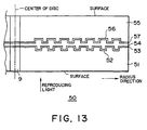
- One example of a multilayer optical disc disclosed in these is shown in Fig. 13.
- Fig. 13 is a cross-sectional view showing one example of a conventional multilayer optical disc, and is a diagram taken along a cutting surface through the center of an optical disc.
- the horizontal direction in the same diagram shows a radius direction of the optical disc; and the vertical direction shows a thickness direction of the optical disc.
- a first recording layer 52 on which information is recorded by a convex and recessed shape information pit is provided on a disc substrate (optically transparent first substrate) 51; and a first reflective layer 53 is provided on the first recording layer 52.
- a second recording layer 56 on which information is recorded by a convex and recessed shape information pit is provided on a disc substrate (optically transparent second substrate) 55; and a second reflective layer 57 is provided on the second recording layer 56.
- Each recording layer side of the first substrate 51 and the second substrate 55, is bonded through a bonding layer 54.
- the optical disc 50 has a thin disc substrate for high-density recording, reducing various optical aberrations due to disc substrate thickness.
- the first substrate 51 and the second substrate 55 have approximately 0.6mm thickness, respectively, and then the two disc substrates are bonded together to have recording space 8 times that of a CD.
- the first recording layer 52 is formed on the first substrate 51 and is provided in proximity to the bonding layer 54, while the second recording layer 56 is formed on the second substrate 55 and is provided near the bonding layer 54.
- two recording layers are provided in proximity to the thickness direction center of the optical disc 50.
- the reflective rate of the first reflective layer 53 is a low reflective rate (e.g. 30%), while that of the second reflective layer 57 is a high reflective rate (e.g. 95%).
- a reproducing laser light is irradiated from the first substrate 51 side as shown in Fig. 13, and is gathered on the first recording layer 52 or the second recording 56 to read information of each recording layer.
- Such reproducing apparatus reproducing a high-density optical disc can naturally reproduce the information on the first recording layer 52 on the second recording layer 56, recorded at a high density; and can generally regenerate a low recording density optical disc like a CD.
- the reading optical head in a high-density optical disc reproducing apparatus has separately the optical system of a high-density disc optical disc and that of a low-density optical disc, or adopts a two-focus hologram-applied optical system; therefore, according to each optical disc, the size of a laser light spot is optimized, and the difference in the disc substrate thickness is corrected.
- a low-density area A and a high-density area B coexisting on one information recording disc meet standard A based on that the entire disc surface is low-density area A, and standard B based on that the entire disc surface is high-density area B, respectively.
- the thickness of the photosensitive agent on an unexposed original disc prepared before recording determines a pit depth. It is generally difficult to change the thickness of the photosensitive agent on one original disc in a 5% or more step-by-step manner. In a normal method, the thickness of the photosensitive agent on one original disc is uniform.
- the low-density area A and the high-density B coexist on one disc, there is a problem of which one the pit depth is produced for.
- the example that the digital signals of the low-density area A and the high-density area B coexist on one disc is described in Japanese Patent Laid-Open No. 168449/1994 mentioned above, but a means for solving the above problems and this problem has not been covered at all.
- the invention For the problem of when the low-density area A and the high-density B coexist on one disc, which one the pit depth (or groove depth) is matched to, the invention combines a method for defining a pit depth in relation to signal output, with a method for defining mechanical and optical accuracies in relation to the disc mechanical accuracy.
- the standard A based on that the entire disc surface is low-density A
- the standard B based on that the entire disc surface is high-density B
- the standard B generally uses a short wavelength laser, having a pit depth shallower than that of the standard A by an approximately short wavelength.
- the standard B defined chronologically in later years is for high-density recording in consideration of use of a relatively short wavelength laser and a relatively high aperture lens; and needs more improvement in disc mechanical and optical accuracies than those of the standard A. Considering these requirements and press technology improvement, the disc mechanical and optical accuracies of the standard B are determined to be higher than those of the standard A.
- This invention is made in consideration of the above problem, and aims to offer an information recording disc having a low-density recording area and high-density recording area with extremely much recording space.
- the information recording disc of the invention provides a first signal recording area on which a first data is recorded, and a second signal recording area that is a signal recording area outside said first area in the radius direction and wherein a second data is recorded at a density higher than that of said first data, and said second data includes the same contents of information as said first data.
- the information recording disc of the invention provides a first signal recording area on which a first data is recorded, and the second signal recording area that is a signal recording area outside said first area in the radius direction and wherein a second data is recorded at a density higher than that of said first data, and a third area that is a signal recording area inside said first area in said radius direction and wherein an information signal related to said second data is recorded at the same recording density as that of said second data.
- the information recording disc of the invention provides a signal recording surface having a first signal recording area and a second signal recording area which is adjacent to said first signal recording area in the radius direction, records a signal at a recording density 2 to 10 times that of said first signal recording area, and has the same signal recording groove depth as that of said first signal recording area, wherein mechanical and optical accuracies determined when recording said signal at the recording density of said second area are applied to the entire of said signal recording surface.
- the information recording disc of the invention wherein a first substrate and a second substrate on which a regenerating light is irradiated are bonded through a bonding layer, comprising: a first recording area in proximity to said bonding layer and formed on the outer part in the radius direction of said information recording disc to record information, and a second recording area in proximity to the surface of said information recording disc and formed on the inner part of said information recording disc in the radius direction to record information at a density lower than that of said first recording layer.
- the information recording disc of the invention wherein a first substrate and a second substrate on which a reproducing light is irradiated are bonded through a bonding layer, comprising: a first recording area in proximity to said bonding layer and formed on the outer part in the radius direction of said information recording disc to record information, a second recording area in proximity to said bonding layer and formed on the inner part in said radius direction to record information, and a second recording area in proximity to the surface of said information recording disc and formed between said outer part and inner part to record information at a density lower than that of said first and second recording areas.
- An optical disc 1 an information recording disc of the invention, provides a signal recording surface 2 having a first area A and a second area B segmented in the radius direction, as shown in Fig. 1.
- Reference numeral 3 is a center hole.
- the first area A is composed of readin area AI, signal recording area AP, and readout area AO.
- the second area B is composed of readin area BI, signal recording area BP, and readout area BO.
- the first embodiment of the information recording disc of the invention is a 120mm diameter audio disc.
- the disc thickness (a distance from a disc surface (protective layer) to a disc signal surface) is 1.2mm.
- the first area A located on the inner side starting reproduction is recorded with a CD format (conforming to JIS S 8605 standard).
- the readin area AI of 23 to 25mm radius, included in the first area A, is recorded by the CD format.
- a status (set a bit showing the kind of an information recording disc) on this readin area AI so that a newly formatted reproducing apparatus (player) can read existence of the second area B, without affecting a conventional CD player at all.
- a definition may be assigned to an unused bit of TOC (Table of Contents) recorded with a CD subcode, to set a status in which the second area B exists.
- the recording density of music information recorded on the signal recording area BP of the second area B is favorably 2 to 10 times the recording density of the signal recording area AP.
- the recording density is 4.5 times (3.7 GB recording space on the entire signal recording surface 2) that of the signal recording area AP (0.8 GB recording space on the entire signal recording surface 2).
- the music sources recorded on the two signal recording areas AP and BP are completely the same.
- the music information program recorded on the signal recording area AP of the first area A is for up to a music signal audible band (to approximately 20 kHz), and becomes data by a CD sampling rate (44.1 kHz sampling frequency) and the number of quantized bits of 16.
- the music information program recorded on the signal recording area BP of the second area B is for up to a music signal ultrasound band above an audible band (to approximately 50 kHz). 88.2 kHz sampling frequency and the number of quantized bits of 20 are relatively higher than the sampling rate and the number of quantized bits used for recording music information on the signal recording area AP.
- a newly formatted reproducing apparatus is used for reproduction of the signal recording area BP of the second area B, combining a unit for increasing regenerating time.
- the music information recorded on the signal recording area BP of the second area B uses reversibly compressed music information data (entropy coded). In this case, on a basis of progressive time apparatus of the music information, the amount of this music information data changes.
- the newly formatted reproducing apparatus uses buffer memory, pickup kick wait and search functions, and reproducing technology (the basic explanation of this technology is described in Japanese Patent Laid-open No. 223669/1989.
- Reversible compression of sampled and quantized music information data is, for example, described in AES-PREPRINT NO-1549 (document) in November of 1979, in which the example that 30 to 40 % of music information data sampled and quantized under a CD condition, can reversibly be compressed is shown.
- This reversible compression uses DPCM technology with a difference from prior data.
- the amount of high-quality music information data of 88.2 kHz sampling and 20-bit quantization is 2.5 times that of CD music information data of 44.1 kHz sampling and 16-bit quantization.
- the embodiment explains the conditions that the recording and reproducing time of music information (music program source) recorded on the signal recording area AP of the first area A, and that on the signal recording area BP of the second area B, are the same and the longest.
- CD-formatted music information data is recorded on the signal recording area AP of the first area A.
- a CD format can record and reproduce up to 74.7-minute music, if all radiuses of 25 to 58mm of a program area (i.e. signal recording area e) are used.
- music information data is recorded at a density 4.5 times that of the signal recording area AP.
- recording and regenerating time of music information recorded on the signal recording area AP of the first area A is X1 minutes
- recording and regenerating time of music information recorded on the signal recording area BP of the second area B is X2 minutes
- the area of a 25 to 58mm radius area (signal recording area e) is normalized as 1
- the normalized area of the first area A would be: X1/74.7
- the normalized area of the second area B would be: X2/336
- the above describes the disc that can record and reproduce 60-minute CD-quality music information on the signal recording area AP of the first area A on the inner side of one optical disc 1, and 60-minute high-quality music information of 88.2 kHz sampling and 20-bit quantization on the signal recording area BP of the second area B outside the disc.
- This disc 1 records the same music information by CD quality that is standard quality, and by quality higher than CD quality, i.e. is a single inventory; therefore it is significant for both music publishers and users who purchase the discs.
- the second embodiment of the information recording disc of the invention is a 120mm diameter audio disc.
- the disc thickness is 1.2mm.
- the second embodiment describes an example that music information data recorded on the signal recording area BP of the second area B, has a fixed transfer rate without reversible compression technology.
- the music information data recorded on the signal recording area AP of the first area A is recorded by a CD format like said first embodiment.
- the recording density of music information data recorded on the signal recording area BP of the second area B is 4.5 times that of the music information data recorded on the signal recording area AP of the first area A.
- the music information sources recorded on the two signal recording areas AP and BP are completely the same.
- the music information data recorded on the signal recording area AP of the first area A is for up to a music signal audible band (to approximately 20 kHz), and becomes data by a CD sampling rate (44.1 kHz sampling frequency) and the number of quantized bits of 16.
- the music information data recorded on the signal recording area BP of the second area B is for up to a music signal ultrasound band above an audible band (to approximately 50 kHz). 88.2 kHz sampling frequency and the number of quantized bits of 20 are relatively higher than the sampling rate and the number of quantized bits used for recording music information on the signal recording area AP.
- the method for recording all this music information data, just as it is, like a CD, has a fixed transfer rate like the CD.
- the embodiment explains the conditions that the recording and reproducing time of music information recorded on the signal recording area AP of the first area A, and that on the signal recording area BP of the second area B, are the same and the longest.
- CD-formatted music information data is recorded on the signal recording area AP of the first area A.
- a CD format can record and regenerate up to 74.7-minute music, if all radiuses of 25 to 58mm of a program area (i.e. signal recording area e) are used.
- recording and reproducing time of music information recorded on the signal recording area AP of the first area A is X1 minutes
- recording and reproducing time of music information recorded on the signal recording area BP of the second area B is X2 minutes
- the area of a 25 to 58mm radius area (signal recording area e) is normalized as 1
- the normalized area of the first area A would be: X1/74.7
- the normalized area of the second area B would be: X2/134.5
- the above describes the disc that can record and reproduce 47-minute CD-quality music information on the signal recording area AP of the first area A on the inner side of one optical disc 1, and 47-minute high-quality music information of 88.2 kHz sampling and 20-bit quantization on the signal recording area BP of the second area B outside the disc.
- This disc 1 records the same music information by CD quality and by quality higher than CD quality, i.e. is a single inventory; therefore it is significant for both music publishers and users who purchase the discs.
- this disc 1 is not reversibly compressed like the first embodiment, extended operation for resetting compression with a regenerating player needed not be performed.
- the third embodiment of the information recording disc of the invention is a 120mm diameter video disc.
- the disc thickness (a distance from a disc surface (protective layer) to a disc signal surface) is 1.2mm.
- the first area A located on the inner side starting reproduction is recorded with a CD format (conforming to JIS S 8605 standard) like said first embodiment.
- the CD format contains a format called a video CD which uses a known MPEG1 standard to record and reproduce an animation of 352 X 240 pixels.
- the readin area AI of 23 to 25mm radius, included in the first area A, is recorded by a video CD format.
- the recording density of video information recorded on the signal recording area BP of the second area B is favorably 2 to 10 times the recording density of the signal recording area AP.
- the recording density is 4.5 times (3.7 GB recording space on the entire signal recording surface 2) that of the signal recording area AP (0.8 GB recording space on the entire signal recording surface 2).
- the video sources recorded on the two signal recording areas AP and BP are completely the same.
- the video information program recorded on the signal recording area BP of the second area B is for moving picture of 720 X 480 pixels using a known MPEG2 standard.
- a compression rate is changed depending on the contents of the moving picture, and a variable transfer rate system that changes a transfer rate is used. Since such example is often explained, the detailed explanation is omitted. It is described in the embodiment that the recording density for a diameter of 120mm with the MPEG2 standard is 4.5 times that of a CD.
- the embodiment explains the conditions that the recording and reproducing time of video information (video program source) recorded on the signal recording area AP of the first area A, and that on the signal recording area BP2 of the second area B, are the same and the longest.
- video CD-formatted video is recorded on the signal recording area AP of the first area A.
- a video CD format can record and reproduce up to approximately 74-minute video, if all radiuses of 25 to 58mm of a program area (i.e. signal recording area e) are used.
- each recording and reproducing time of the first and second areas is approximately 47 minutes.
- the above describes the disc that can record and reproduce approximately 47-minute CD-quality video information on the signal recording area AP of the first area A on the inner side of one optical disc 1, and approximately 47-minute high-quality video information of 88.2 kHz sampling and 20-bit quantization on the signal recording area BP of the second area B outside the disc.
- This disc 1 records the same video information by MPEG1 and MPEG2 qualities i.e. is a single inventory; therefore it is significant for both publishers and users who purchase the discs.
- an optical disc 10 that is another information recording disc of the invention provides a signal recording surface 20 having the first area A and the second area B segmented sequentially in the radius direction from the center hole 3, as shown in Fig. 4.
- a third area CC is provided on the inner side (the center hole 3 side) adjacent to the first area A.
- a readin signal in relation to a first data recorded on the second area B that is an information signal that has the same recording density as that of the first data, is recorded on the third area CC.
- This information signal is a readin signal focusing on a test signal correcting TOC (contents) information and a player.
- a is a radius of the optical disc 10
- b is a radius from the center o of the center hole 3 to outermost (readout) part of the signal recording surface 20
- c is a radius from the center o of the center hole 3 to innermost (readin) part of the signal recording surface 20
- d is a radius of the center hole 3
- e is a signal recording area of the signal recording surface 20.
- the first area A is composed of readin area AI, signal recording area AP, and readout area AO.
- the second area B is composed of readin area BI1, signal recording area BP, and readout area BO.
- the third area CC is readin area BI2 that records a readin signal having at least data of a readin signal recorded on the readin area BI1.
- the contents of a readin signal recorded on the readin area BI1 of the second area B is duplicated with the contents of a readin signal recorded on the third area CC; therefore if the readin signal recorded on the third area CC is considered main, it is not inconvenient to, if necessary, change (reduce) the contents of the readin signal recorded on the readin area BI1 of the second area B (simplification of the readin signal recorded on the readin area BI1).
- the disc thickness (a distance from disc surface (protective layer) to disc signal surface) is 1.2mm.
- the first area A located on the inner side starting reproducing is recorded with a CD format (conforming to JIS S 8605 standard).
- 23 to 25mm radius readin area AI, included in the first area A, is recorded by a CD format.
- a definition may be assigned to an unused bit of TOC (Table of Contents) recorded with a CD subcode, to set a status in which the second area B exists.
- the defined length of a readout track (readout area AO) is recorded on the first area A for termination.
- the music information program recorded on the signal recording area AP of the first area A becomes data by a CD sampling rate (44.1 kHz sampling frequency) and the number of quantized bits of 16.
- the recording density of music information recorded on the signal recording area BP of the second area B is favorably 2 to 10 times the recording density of the signal recording area AP.
- the recording density is 4.5 times (3.7 GB recording space on the entire signal recording surface 2) that of the signal recording area AP (0.8 GB recording space on the entire signal recording surface 2).
- the music sources recorded on the two signal recording areas AP and BP are completely the same.
- a newly formatted reproducing apparatus (player) is used for reproduction of the signal recording area BP of the second area B.
- the newly formatted reproducing apparatus uses buffer memory, pickup kick wait and search functions, and reproducing technology (the basic explanation of this technology is described in Japanese Patent Laid-Open No. 223669/1989).
- this player can determine the side more inner than a CD format, e.g. the third area CC provided with a radius of 22.5 to 23mm, as a readin area.
- a CD player and a high-density newly formatted player can first reproduce a readin area corresponding to each recording density, optimizing a signal reading condition for each player.
- optical disc 100 that is an information recording disc of the invention, with a different structure from that of both the above optical discs 1 and 10, is explained.
- a CD as a music information recording disc is well known in the art.
- the CD reading is system-designed so as to use a 780nm laser wavelength, while a laser with around a 635nm laser light wave has been practiced in recent years; a high-density disc that reads with this is under development. Here it is called high-density CD.
- a high-density CD disc under development that is not of a public standard, is system-designed so as to read with a short wavelength laser of around 635nm.
- the pit depth of the disc is determined in relation to 0.25 times a reading laser wavelength. The invention is explained below by taking a disc wherein many pit rows form a signal track to record information, as an example.
- a pit depth is not defined as a standard, a reproducing signal characteristic with a standard light pickup to be defined with a standard, is defined with a range. As a result, the pit depth is determined with a range.
- the recording original disc film thickness directly related to the pit depth is equivalently approximately 100 to 125nm to satisfy a CD standard; and is equivalently approximately 85 to 105nm for a high-density CD standard. Since the reproducing signal characteristic related to the pit depth is not determined only by the recording original disc film thickness, and is changed by conditions of: recording development, pressing stamper producing, press and so on, here "equivalently" is represented with the value of the recording original disc film thickness, including these fluctuations.
- the pit shallower than a standard value increases push pull tracking output obtained by differentially detecting the reflective light of a reading laser that is irradiated on the pit, and decreases a degree of modulation of the signal.
- the pit deeper than a standard value decreases push pull tracking output, and increases a degree of modulation of the signal.
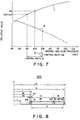
- Fig. 7 In the same diagram, I is a degree of modulation of a CD signal; and II is the push pull tracking output of a high-density CD signal.
- the recording original disc film thickness range satisfying both standards is equivalently 100 to 105nm, as shown in a control width DD (illustrated in Fig. 7), and is narrow for a producing control width (an equivalent film thickness control width for production with disc producing steps).
- the reproducing signal characteristic related to the pit depth is not determined only by the recording original disc film thickness, and is changed by the conditions of: recording development, pressing stamper producing, press and so on, requiring control including these.
- a disc warp (tilt) characteristic is 0.6 degrees for a CD standard, and is, e.g. 0.35 degrees for a high-density CD standard.
- the tilt for the regenerating signal deterioration on the CD area is not, as a typical item, 0.6 degrees, but may be allowed for 0.35 degrees.
- the main operation of the invention is that allowance for CD area reproduction produced by less allowance for the reproducing signal deterioration that is the above 0.35-degree tilt, is devoted to resolve an equivalent recording original disc film thickness range of a narrow producing control width DD of 100 to 105nm.
- DD narrow producing control width
- the equivalent recording original disc film thickness range satisfying both of the high-density CD standard and the CD area standard after change is approximately 95 to 105nm, as shown with a control width E in Fig.
- the disc of the invention is approximately 0.7 times that of recording said entire signal recording surface at a recording density of the CD area. In terms of the intensity of a signal, a higher degree of modulation is better, and favorably 0.8 to 0.95 times.
- improvement in such as shake and eccentricity other than the tilt is contributed as improvement in a reproducing signal.
- the described mechanical accuracy standard, and an optical accuracy such as a refractive characteristic are alike.
- the above describes the embodiment of the information recording disc with reasonability shown by the deteriorated and improved amount of jitter, mechanical and optical accuracies standards of a disc based on that the entire disc surface has the density of a high-density CD area, is applied to all areas of a disc having a CD area and a high-density CD area of the invention; and the signal characteristic standard of the CD area of the disc of the invention is changed, in comparison with that of a standard based on that the entire disc surface has the density of the CD area.
- the invention is explained with an example of a phase pit by placing emphasis on understandability. This is alike to the depth of a groove tracking.
- the invention can be applied to a disc with a recording and reproducing method changing the amount of a reflective light, and a optical magnet method changing the polarized angle of a reflective light.
- the optical disc 100 that is the fifth embodiment of the information recording disc of the invention, provides the signal recording surface 200 having the first area A and the second area B segmented sequentially in the radius direction from the center hole 3, as shown in Fig. 6. Also the third area CC is provided on the inner side (the center hole 3 side) adjacent to the first area A.
- the diameter of the optical disc 100 is 120mm; the radius "a” is 60 mm; and the diameter of the center hole 3 is 15mm.
- the third area CC is a readin area wherein a readin signal in relation to a second data recorded on the second area B is recorded at the same recording density as that of the second data.
- This readin signal focuses on a test signal correcting TOC information and a player.
- the radius "a” is 60mm
- the radius "b” is 58.5mm
- the radius "c” is 25mm + 0mm to 25mm - 0.2mm
- the radius dd is 23.0mm + 0mm to 23.0mm - 0.2mm
- the radius ee is from the center “o” to max. 22.5mm
- the radius "f" is 7.5mm.
- the first area A is composed of readin area AI that is the first readin area, signal recording area AP on which the first data is recorded, and readout area AO.
- the second area B is composed of readin area BI1, signal recording area BP on which the second data is recorded, and readout area BO that is the second readout area.
- the third area CC is the second readin area, and readin area BI2 recording a readin signal having at least data of a readin signal recorded on the readin area BI1 of the second area B.
- the contents of a readin signal recorded on the readin area BI1 of the second area B is duplicated with the contents of a readin signal recorded on the third area CC; therefore if the readin signal recorded on the third area CC is considered main, it is not inconvenient to, if necessary, change (reduce) the contents of the readin signal recorded on the readin area BI1 of the second area B (simplification of the readin signal recorded on the readin area BI1).
- TOC information records repeatedly the same data with 2mm or more width in the radius direction to avoid reading miss.
- the readin signal recorded on the readin area BI1 writes the TOC information only with 0.3mm width in the radius direction.
- the recording space on the readin area BI1 can be reduced. Only this reduced space may be devoted to an increase in the recording space of the signal recording area BP.
- the information recording disc of the invention is concretely explained with a 120 mm diameter audio disc.
- the disc thickness (a distance from a disc surface (protective layer) to a disc signal surface) is 1.2mm.
- the first area A and the second area B have the same pit depth.
- the first area A located on the inner side starting reproduction is recorded with a CD format (conforming to JIS S 8605 standard).
- the readin area AI of 23 to 25mm radius, included in the first area A, is recorded by the CD format.
- a definition may be assigned to an unused bit of TOC (Table of Contents) recorded with a CD subcode, to set a status in which the second area B exists.
- the defined length of a readout track (readout area AO) is recorded on the first area A for termination.
- the music information program recorded on the signal recording area AP of the first area A becomes data by a CD sampling rate (44.1 kHz sampling frequency) and the number of quantized bits of 16.
- the recording density of music information recorded on the signal recording area BP of the second area B is favorably 2 to 10 times the recording density of the signal recording area AP.
- the recording density is 4.5 times (3.7 GB recording space on the entire signal recording surface 200) that of the signal recording area AP (0.8 GB recording space on the entire signal recording surface 2).
- the music sources recorded on the two signal recording areas AP and BP are completely the the same.
- a newly formatted reproducing apparatus (player) is used for reproduction of the signal recording area BP of the second area B.
- the newly formatted reproducing apparatus uses buffer memory, pickup kick wait and search functions, and reproducing technology (the basic explanation of the technology is described in Japanese Patent Laid-Open No. 223669/1989).
- this player can determine the side more inner than a CD format, e.g. the third area CC provided with a radius of 22.5 to 23mm, as a readin area.
- a CD player and a high-density newly formatted player can first reproduce a readin area corresponding to each recording density, optimizing a signal reading condition for each player.
- the above optical disc 100 records information on the first area A at a low recording density of a CD, and records information on the second area B at a high recording density of a high-density CD.
- the invention is not limited to this construction, the optical disc may record information on the first area A at a high recording density of a high-density CD, and record information on the second area B at a low recording density of a CD.
- Two-disc bonded construction of the information recording medium of the invention is explained along Figs. 9 to 12.
- Fig. 9 is a cross-sectional view showing the sixth embodiment of the information recording disc in relation to the invention, and is a cross-sectional view cut on a cross section through the center of a optical disc 200.
- a first recording layer 220 wherein a convex and recessed shape information pit is formed spirally on the outer side thereof, is formed.
- a first reflective layer 230 is multilayered.
- a second recording layer 260 wherein a convex and recessed shape information pit is spirally formed on the inner side thereof, is formed.
- a second reflective layer 270 and a protective layer 280 are formed on this second recording layer 260.
- Both of said first substrate 210 and second substrate 250 have a disc thickness of approximately 0.6mm, said first recording layer 220 being recorded according to high-density recording specifications, e.g. at a recording density 4 times that of a CD, and said second recording layer 260 being recorded according to low-density recording specifications, e.g. at the same recording density as that of a CD.
- the optical disc 200 is produced by bonding through a bonding layer 240 the first substrate 210 and second substrate 250 that are worked as described above.
- said first recording layer 220 is located near the center of the thickness direction of the optical disc 200, i.e. near the bonding layer 240; and said second recording layer 260 is located near a surface 340 of the optical disc 200.
- the reflective rate of said first reflective layer 230 is approximately 95%; and the reflective rate of said second reflective layer 270 is also approximately 95%.
- Said optical disc 200 is regenerated by irradiating a laser light (regenerating light) from a surface 330 side of the optical disc.
- the optical disc 200 has a construction bonding two disc substrates of a thickness of 0.6mm. Also on the second recording layer 260 located in proximity to the surface 340 opposite to a signal reading side, information is recorded at a low density like a CD on the inner side of the disc 200, and the second reflective layer 270 is coated thereon. The thickness of said optical disc 200 bonded is 1.2mm, which is optimum for a currently-common CD player.
- coating of the first reflective layer 230 is not formed on the inner side by taking a means such as masking. For this reason, a reproducing laser light arrives at the second recording layer 260 with little loss; and the reflective light reaches a reading optical head with little loss.
- Said first recording layer 220 is formed only on the outer side in proximity to the bonding layer 240, and records information with high-density optical disc specifications.
- the first reflective layer 230 is coated to reflect a regenerating light.
- the thickness of the optical disc in this part is substantially 0.6mm, and is suitable for a high-density optical disc, and a high-density optical disc regenerating apparatus.
- Fig. 10 is a cross-sectional view showing an optical disc 400 that is the seventh embodiment of the invention. Unlike the optical disc 200 shown in Fig. 9, a first recording layer 220a recorded at a high density is not formed on a first substrate 210a side, but on a second substrate 250a side.
- the first substrate 210a is an optically transparent disc that does not record information. Said first substrate 210a and second substrate 250a have a thickness of approximately 0.6mm, and are bonded through the bonding layer 240a.
- Fig. 11 is a cross-sectional view showing an optical disc 500 that is the eighth embodiment of the invention. Unlike the optical disc 200 shown in Fig. 9, a third recording layer 320 recorded at a high density is formed on the second substrate 250a side; and the reflective rate of said first reflective layer 230 is a high reflective rate or low reflective rate.
- the first substrate 210 is an optically transparent disc that does not record information.
- Said first substrate 210 and second substrate 250a have a thickness of approximately 0.6mm, and are bonded through the bonding layer 240a.
- Said third recording layer 320 is formed on the bonding layer 240a side of said second substrate 250a, and is provided on the outer side like the first recording layer 220. Also a third reflective layer 310 is multilayered on said third recording layer 320.
- the reflective rate of said first reflective layer 230 is approximately 30% or 95%; and the reflective rate of said second reflective layer 270 and third reflective layer 310 is approximately 95 %.
- the high-density recording part on the optical disc 500 is double sided, and is a so-called dual-layer disc, if the first reflective layer 230 is a semipermeable film; therefore, the recording layers 230 and 260 can be regenerated from the single side.
- the first reflective layer 230 and the third reflective layer 310 have both a high reflective rate, the first recording layer 220 and the third recording layer 320 are regenerated by reversing the irradiating direction of a laser light.
- Fig. 12 is a explanation view of an unrecordable part wherein a high-density recording part is double sided.
- the location of said second recording layer 260 is shown on the same location as the surface 340 of the optical disc 500, omitting the thickness of said bonding layer 240.
- Said first recording layer 220 and third recording layer 320 are provided on the outer side from a radius r1; and said second recording layer 260 is provided on the inner side from a radius r2. Also a laser light regenerating information of the second recording layer 260 of the optical disc 500 is irradiated from said first substrate 210 side through an objective lens 350.
- an unrecordable part is produced between an area of the inner side from the radius r2 and an area of the outer side from the radius r1.
- (r1 - r2) may be called crossing length and is shown with L in the diagram.
- said L needs to satisfy the following equation: L > (dd/2) * tan (arcsin (NA/n) ) where n is the reflective rate of the first substrate 210 and the second substrate 250a, and NA is the number of apertures of the objective lens 350.
- a CD player starts reproduction from the innermost part of the optical disc.
- the optical disc of the invention is reproduced in a low-density optical disc reproducing apparatus, the information of said second recording layer 260 on which low-density recording is made, is reproduced without any problem.
- a high-density optical disc reproducing apparatus first regenerates information from the innermost part of the optical disc.
- An idea favorable for this reproducing sequence is put into the optical disc of the invention. In other words, it is favorable for building the reproducing sequence according to various programs, if it is found at starting reproduction that the high-density optical disc reproducing apparatus records, on the outer part, information recorded at a high-density. This point is explained, based on the ninth and tenth embodiments of the optical disc of the invention.
- TOC Contents information called TOC is recorded on the innermost part of a low-density optical disc like a CD.
- a CD player first reproduces said TOC information, checks the relation between program contents and a recorded location, and then reproduces necessary information.
- information showing high-density recording is made on the outer part, is recorded on the innermost part of the recording area of the second recording layer 260 in Fig. 9. This information is recorded e.g. on the subcode area of a CD signal. It is no problem, because a high-density optical disc reproducing apparatus can reproduce the low-density recording area on the inner part.
- the tenth embodiment (unillustrated) of the invention is explained.
- the high-density recording area on the optical disc of the tenth embodiment is provided on the innermost part as well as on said outer part.
- a high-density recording area is provided on the outer part area from said first recording layer 220 and on the inner side area from said second recording layer 220.
- Information showing there is high-density recorded information on the outer side is recorded at a low density on the high-density recording area of said innermost part.
- the high-density recording area on said innermost part is flush with the high-density recording area of said outer part (first recording layer 220 or third recording layer 320).
- the thicknesses of said first substrate 210 and second substrate 250 (250a) are not limited to 0.6mm, and may be not always equal. For example, if higher density recording and reproduction become possible by advancing the development in a blue laser in the future, it is considered that the thickness of said first substrate 210 is 0.4 mm; that of said second substrate 250 (250a) is 0.6mm. Also, when the same contents of information (program) is recorded on said low-density recording layer and high-density recording layer, optical disc manufacturers have the advantages of reducing the number of the kinds of optical discs, and of promoting unpopular high-density optical discs.
- an information recording disc that can reproduce a first area on the inner side of the disc using a reproducing apparatus conventionally owned by users, and can reproduce a higher quality second area using the same disc as a new high-density disc reproducing apparatus purchased, which is a single inventory recording the same information of different qualities on the first and second areas so that two kinds of discs are not produced and stocked separately for increasing producing efficiency and for reducing distribution inventories to half, being extremely favorable for manufactures and sellers, and further being significant for users buying the discs.
- a first area on the inner side of a disc can be reproduced using a conventionally-owned reproducing apparatus for normal quality; and a second area outside the disc can be reproduced using a reproducing apparatus for high quality.
- a conventionally-owned reproducing apparatus CD player
- a new high-density disc reproducing apparatus high-density newly-formatted player
- an information signal i.e. readin signal recorded on readin area BI1
- the contents of the readin signal recorded on the second area can be simplified, increasing the recording space of the first data signal of the second area for this recording space simplified and reduced.
- a conventionally-owned reproducing apparatus for normal quality can reproduce a first area on the inner side of the disc, just as it is; and a reproducing apparatus for ultrahigh quality, led by the information signal of a third area, can reproduce reliably a second area of the inner and outer sides of the disc.
- an optical disc on which a phase pit or groove is formed providing: a signal recording surface being segmented into a first area and a second area in the radius direction, the recording density of the second area being 2 to 10 times that of the first area, pit depths of the first and second areas being the same, and mechanical and optical accuracies standards of the disc based on that the entire disc surface has the density of the second area being applied to all areas of the disc composed of the first area and the second area of the invention, the productivity of the information recording disc can be improved without deteriorating the total reproducing characteristic, by changing the signal characteristic standard of the first area of the disc of the invention, in comparison with the signal characteristic standard based on that the entire disc surface has the density of the first area.
- an information recording disc that can reproduce a first area on the inner side of the disc using a reproducing apparatus conventionally owned by users, and can reproduce a higher quality second area using the same disc as a new high-density disc reproducing apparatus purchased, wherein recording the same music source on the disc at a normal density (normal quality) and a high density (high quality), can reproduce the first area on the inner side of the disc using a conventionally-owned reproducing apparatus for normal quality, and the second area outside the disc using a regenerating apparatus for high quality.
- a conventionally-owned reproducing apparatus CD player
- a new high-density disc reproducing apparatus high-density newly-formatted player
- an information signal i.e. readin signal recorded on readin area BI1
- the contents of the readin signal recorded on the second area can be simplified, increasing the recording space of the first data signal of the second area for this recording space simplified and reduced.
- a conventionally-owned reproducing apparatus for normal quality can reproduce a first area on the inner side of the disc, just as it is; and a reproducing apparatus for ultrahigh quality, led by the information signal of a third area, can reproduce reliably a second area of the inner and outer sides of the disc.
- the same information recording disc can be reproduced with a low-density optical disc reproducing apparatus and a high-density optical disc reproducing apparatus.
- molding and producing an optical disc are easier than forming a plurality of recording layers on one substrate.
- a high-density optical disc reproducing apparatus may first reproduce the innermost part like a low-density optical disc reproducing apparatus, facilitating reproducing control.
Landscapes
- Engineering & Computer Science (AREA)
- Software Systems (AREA)
- Theoretical Computer Science (AREA)
- Signal Processing (AREA)
- Optical Recording Or Reproduction (AREA)
- Signal Processing For Digital Recording And Reproducing (AREA)
Applications Claiming Priority (9)
| Application Number | Priority Date | Filing Date | Title |
|---|---|---|---|
| JP100540/95 | 1995-03-30 | ||
| JP10054095 | 1995-03-30 | ||
| JP10022095 | 1995-03-31 | ||
| JP100220/95 | 1995-03-31 | ||
| JP328346/95 | 1995-11-22 | ||
| JP32834695 | 1995-11-22 | ||
| JP333980/95 | 1995-11-29 | ||
| JP33398095 | 1995-11-29 | ||
| PCT/JP1996/000830 WO1996030906A1 (en) | 1995-03-30 | 1996-03-28 | Information recording disk |
Publications (2)
| Publication Number | Publication Date |
|---|---|
| EP0818784A1 true EP0818784A1 (de) | 1998-01-14 |
| EP0818784A4 EP0818784A4 (de) | 1999-09-08 |
Family
ID=27468809
Family Applications (1)
| Application Number | Title | Priority Date | Filing Date |
|---|---|---|---|
| EP96907695A Withdrawn EP0818784A4 (de) | 1995-03-30 | 1996-03-28 | Informationsaufzeichnungsplatte |
Country Status (6)
| Country | Link |
|---|---|
| US (1) | US6038208A (de) |
| EP (1) | EP0818784A4 (de) |
| KR (1) | KR100309587B1 (de) |
| CN (1) | CN1185227A (de) |
| TW (1) | TW322575B (de) |
| WO (1) | WO1996030906A1 (de) |
Cited By (6)
| Publication number | Priority date | Publication date | Assignee | Title |
|---|---|---|---|---|
| EP0949617A1 (de) * | 1998-04-09 | 1999-10-13 | Sony Corporation | Plattenwiedergabegerät und Verfahren |
| EP1155411A1 (de) * | 1999-02-23 | 2001-11-21 | Stefan Mais | Datenträger mit verschieden formatierten audio- und videodaten sowie dazugehörige(s) aufzeichnungsvorrichtung und -verfahren |
| EP1187129A2 (de) | 2000-08-28 | 2002-03-13 | Sony Corporation | Datenaufzeichnungsmedium, Datenaufzeichnungsverfahren, Datenaufzeichnungsgerät, Zugriffsverfahren, und Zugriffsgerät |
| EP1205917A3 (de) * | 2000-11-07 | 2004-05-19 | Pioneer Corporation | Mehrschichtige Platte und Gerät zur Wiedergabe von mehrschichtigen Platten |
| US6788634B1 (en) | 1999-07-15 | 2004-09-07 | Micronas Gmbh | Playback apparatus |
| EP1118988A4 (de) * | 1999-07-12 | 2005-11-16 | Matsushita Electric Industrial Co Ltd | Optisches informationsaufzeichnungsmedium und verfahren zur initialisierung desselben |
Families Citing this family (26)
| Publication number | Priority date | Publication date | Assignee | Title |
|---|---|---|---|---|
| DE69618722T2 (de) * | 1995-08-09 | 2002-08-22 | Sony Corp., Tokio/Tokyo | Aufzeichnungsmedium, Aufzeichnungsgerät und Wiedergabegerät |
| JP3674092B2 (ja) * | 1995-08-09 | 2005-07-20 | ソニー株式会社 | 再生装置 |
| JP3248415B2 (ja) | 1995-11-21 | 2002-01-21 | 松下電器産業株式会社 | 多層ディスク |
| KR100354418B1 (ko) * | 1996-12-04 | 2002-09-28 | 마쯔시다덴기산교 가부시키가이샤 | 고해상도 및 입체 영상 기록용 광디스크, 광디스크 재생 장치,및 광디스크 기록 장치 |
| AU7935198A (en) * | 1997-07-01 | 1999-01-25 | Sanyo Electric Co., Ltd. | Recording medium, recorder, and player |
| US6925250B1 (en) | 1997-08-29 | 2005-08-02 | Matsushita Electric Industrial Co., Ltd. | Optical disc for recording high resolution and normal image, optical disc player, optical disc recorder, and playback control information generator |
| US6310854B1 (en) | 1997-11-28 | 2001-10-30 | Yamaha Corporation | Optical disk having areas of different recording densities or functions |
| JPH11167729A (ja) * | 1997-12-03 | 1999-06-22 | Yamaha Corp | 光ディスクのシーク動作制御方法及び装置 |
| EP0938090B1 (de) * | 1998-02-19 | 2003-06-25 | Micronas GmbH | Audioabspielgerät |
| US7092340B2 (en) | 2000-07-13 | 2006-08-15 | Micronas Gmbh | Playback apparatus |
| JP2002074849A (ja) * | 2000-08-28 | 2002-03-15 | Sony Corp | データ記録媒体、データ記録方法および装置、並びにアクセス方法および装置 |
| US6894967B2 (en) * | 2000-11-21 | 2005-05-17 | Yamaha Corporation | Optical disk recorder for writing data with variable density |
| CN1306516C (zh) | 2001-11-09 | 2007-03-21 | 株式会社东芝 | 信息记录/还原系统和记录校正方法 |
| KR100455381B1 (ko) * | 2002-02-28 | 2004-11-06 | 삼성전자주식회사 | Odd 제품의 성능을 향상시키기 위한 디스크 및 그 제조방법 |
| BR0313037A (pt) | 2002-08-03 | 2005-07-05 | Samsung Electronics Co Ltd | Método de gravação/reprodução de informações em/de uma mìdia de armazenamento de informações mediante utilização de informações de controle incluindo informações de versão, mìdia de armazenamento de informações, aparelho de gravação e/ou reprodução para gravação e/ou reprodução de dados relativamente a uma mìdia de armazenamento de informações possuindo informação de disco incluindo informações de controle existentes e informações de controle atualizadas, mìdia de armazenamento de informações passìvel de utilização para gravação/reprodução por uma unidade de leitura/reprodução de dados de acordo com informação de disco, aparelho de gravação e/ou reprodução para gravação e/ou reprodução de dados, método de transferência de dados com relação a uma mìdia de armazenamento de informações de acordo com informação de disco detectadas lidas da mìdia de armazenamento de informações, e mìdia passìvel de leitura em computador |
| KR20040013314A (ko) * | 2002-08-05 | 2004-02-14 | 삼성전자주식회사 | 멀티 포맷 기록 및 재생 장치와 방법, 및 저장 매체 |
| JP4075744B2 (ja) * | 2003-02-12 | 2008-04-16 | 日産自動車株式会社 | 燃料タンクの取付構造 |
| KR100750109B1 (ko) * | 2003-02-15 | 2007-08-21 | 삼성전자주식회사 | 정보 저장매체 |
| US20060209665A1 (en) * | 2003-03-17 | 2006-09-21 | Koninklijke Philips Electronics N.V. | Multi-speed recordable information carrier |
| JP3871060B2 (ja) * | 2003-03-25 | 2007-01-24 | 株式会社リコー | 光記録媒体及び情報記録方法 |
| JP2004327013A (ja) * | 2003-04-11 | 2004-11-18 | Nec Corp | 光ディスク媒体および光ディスク装置 |
| US6880843B1 (en) | 2003-05-28 | 2005-04-19 | Melville T. Greer, Jr. | Vehicle step device |
| US7916582B2 (en) * | 2004-05-11 | 2011-03-29 | Samsung Electronics Co., Ltd. | Optical recording medium, recording/reproducing apparatus and method, initialization method, and reinitialization method |
| US7663990B2 (en) * | 2004-05-21 | 2010-02-16 | Samsung Electronics Co., Ltd. | Optical recording medium having access control area and method for recording or reproducing thereof |
| US7697404B2 (en) * | 2005-10-12 | 2010-04-13 | International Business Machines Corporation | Medium, system, and method for a common optical data storage medium depression depth |
| JP2012009133A (ja) * | 2011-09-05 | 2012-01-12 | Toshiba Corp | 情報記憶媒体、情報再生方法、情報再生装置、情報記録方法及び情報記録装置 |
Family Cites Families (23)
| Publication number | Priority date | Publication date | Assignee | Title |
|---|---|---|---|---|
| JPS52135613A (en) * | 1976-05-10 | 1977-11-12 | Sony Corp | Information recording media |
| US4298897A (en) * | 1979-09-20 | 1981-11-03 | International Business Machines Corporation | Buffered recording |
| JPS5746364A (en) * | 1980-09-04 | 1982-03-16 | Matsushita Electric Ind Co Ltd | Disk reproducer |
| JPS61142503A (ja) * | 1984-12-15 | 1986-06-30 | Pioneer Electronic Corp | 情報記録方式 |
| JPH0711849B2 (ja) * | 1987-02-27 | 1995-02-08 | 株式会社東芝 | フロツピ−デイスク装置のデ−タ記録制御装置 |
| JPS6442028A (en) * | 1987-08-07 | 1989-02-14 | Pioneer Electronic Corp | Composite disk |
| JP2516041B2 (ja) * | 1988-03-02 | 1996-07-10 | 日本ビクター株式会社 | 回転記録媒体円盤に対するデジタル信号の記録再生方式 |
| JPH02101678A (ja) * | 1988-10-06 | 1990-04-13 | Matsushita Electric Ind Co Ltd | 光ディスク |
| JPH0823941B2 (ja) * | 1988-11-08 | 1996-03-06 | パイオニア株式会社 | 光学式情報記録担体及びその製造方法 |
| JPH02193317A (ja) * | 1989-01-20 | 1990-07-31 | Matsushita Electric Ind Co Ltd | 光ディスク |
| JPH0317867A (ja) * | 1989-06-14 | 1991-01-25 | Hitachi Ltd | 磁気記憶装置 |
| JPH0379790A (ja) * | 1989-08-23 | 1991-04-04 | Sumitomo Electric Ind Ltd | 耐食高張力鋼線およびそれを用いた耐食コイルバネ |
| JPH03183091A (ja) * | 1989-12-12 | 1991-08-09 | Matsushita Electric Ind Co Ltd | 画像ファイルシステムの記録再生方法 |
| JPH03245360A (ja) * | 1990-02-23 | 1991-10-31 | Matsushita Electric Ind Co Ltd | 情報記録再生装置 |
| JP2940208B2 (ja) * | 1991-04-12 | 1999-08-25 | 松下電器産業株式会社 | 記録再生方法、および記録再生装置、光ディスク |
| JPH056571A (ja) * | 1991-06-28 | 1993-01-14 | Pioneer Electron Corp | 光学式情報記録媒体 |
| JP3017867B2 (ja) | 1991-11-29 | 2000-03-13 | 株式会社東芝 | 交直変換装置の制御装置 |
| JP3373221B2 (ja) * | 1992-03-04 | 2003-02-04 | パイオニアビデオ株式会社 | ディジタルオーディオ信号の記録再生装置 |
| JP3233232B2 (ja) * | 1992-06-19 | 2001-11-26 | ソニー株式会社 | 動画像復号化方法および装置 |
| JP3179598B2 (ja) * | 1992-11-30 | 2001-06-25 | 株式会社日立製作所 | 光ディスク |
| JP2532818B2 (ja) * | 1993-02-01 | 1996-09-11 | 松下電器産業株式会社 | 対物レンズおよび光ヘッド装置 |
| JPH06274940A (ja) * | 1993-03-23 | 1994-09-30 | Matsushita Electric Ind Co Ltd | 光ディスク及びその製造方法 |
| JPH07114733A (ja) * | 1993-08-26 | 1995-05-02 | Pioneer Electron Corp | 光ディスク及びその記録方法 |
-
1996
- 1996-03-28 KR KR1019970707034A patent/KR100309587B1/ko not_active Expired - Fee Related
- 1996-03-28 US US08/930,344 patent/US6038208A/en not_active Expired - Fee Related
- 1996-03-28 EP EP96907695A patent/EP0818784A4/de not_active Withdrawn
- 1996-03-28 CN CN96194045A patent/CN1185227A/zh active Pending
- 1996-03-28 WO PCT/JP1996/000830 patent/WO1996030906A1/ja not_active Ceased
- 1996-04-01 TW TW085103810A patent/TW322575B/zh active
Cited By (11)
| Publication number | Priority date | Publication date | Assignee | Title |
|---|---|---|---|---|
| EP0949617A1 (de) * | 1998-04-09 | 1999-10-13 | Sony Corporation | Plattenwiedergabegerät und Verfahren |
| US6141299A (en) * | 1998-04-09 | 2000-10-31 | Sony Corporation | Apparatus and method for reproducing information data of different formats from a multi-layer optical disc |
| EP1155411A1 (de) * | 1999-02-23 | 2001-11-21 | Stefan Mais | Datenträger mit verschieden formatierten audio- und videodaten sowie dazugehörige(s) aufzeichnungsvorrichtung und -verfahren |
| EP1118988A4 (de) * | 1999-07-12 | 2005-11-16 | Matsushita Electric Industrial Co Ltd | Optisches informationsaufzeichnungsmedium und verfahren zur initialisierung desselben |
| US6788634B1 (en) | 1999-07-15 | 2004-09-07 | Micronas Gmbh | Playback apparatus |
| EP1187129A2 (de) | 2000-08-28 | 2002-03-13 | Sony Corporation | Datenaufzeichnungsmedium, Datenaufzeichnungsverfahren, Datenaufzeichnungsgerät, Zugriffsverfahren, und Zugriffsgerät |
| EP1187129A3 (de) * | 2000-08-28 | 2006-09-06 | Sony Corporation | Datenaufzeichnungsmedium, Datenaufzeichnungsverfahren, Datenaufzeichnungsgerät, Zugriffsverfahren, und Zugriffsgerät |
| KR100812819B1 (ko) * | 2000-08-28 | 2008-03-12 | 소니 가부시끼 가이샤 | 데이터 기록매체, 데이터 기록방법 및 장치와 액세스방법및 장치 |
| EP1205917A3 (de) * | 2000-11-07 | 2004-05-19 | Pioneer Corporation | Mehrschichtige Platte und Gerät zur Wiedergabe von mehrschichtigen Platten |
| US6977880B2 (en) | 2000-11-07 | 2005-12-20 | Pioneer Corporation | Multi-layered disc and multi-layered disc reproducing apparatus |
| US7301876B2 (en) | 2000-11-07 | 2007-11-27 | Pioneer Corporation | Multi-layered disc and multi-layered disc reproducing apparatus |
Also Published As
| Publication number | Publication date |
|---|---|
| TW322575B (de) | 1997-12-11 |
| WO1996030906A1 (en) | 1996-10-03 |
| US6038208A (en) | 2000-03-14 |
| CN1185227A (zh) | 1998-06-17 |
| KR19980703635A (ko) | 1998-12-05 |
| KR100309587B1 (ko) | 2001-12-17 |
| EP0818784A4 (de) | 1999-09-08 |
Similar Documents
| Publication | Publication Date | Title |
|---|---|---|
| US6038208A (en) | Information recording disc recorded with signals at two different recording densities | |
| US8411541B2 (en) | Optical recording medium having read-only storage area and writable storage area and recording/reproducing apparatus and method therefor | |
| US5966367A (en) | Optical information recording medium | |
| AU647818B2 (en) | Disc-shaped recording medium | |
| EP0856186B1 (de) | Informationsspeichermedium, informationswiedergabeverfahren und informationswiedergabegerät | |
| EP1168315A2 (de) | Optisches Aufzeichnungsmedium mit einem nur-Lese-Speicherberich und einem beschreibbaren Speicherbereich, und Aufzeichnungs-/-Wiedergabegegerät und Verfahren dafür | |
| JPH04103079A (ja) | 円盤状記録媒体の記録装置及び再生装置 | |
| Yoshida | The rewritable MiniDisc system | |
| EP1500094A1 (de) | Doppelschichtiges optisches datenaufzeichnungsmedium | |
| US7215626B2 (en) | Optical disk recording apparatus, optical disk recording method, optical disk reproducing apparatus, and optical disk capable of interlayer crosstalk reduction | |
| US5995457A (en) | Method of masking data on digital video disks (DVD) | |
| US20080123491A1 (en) | Optical recording medium having read-only storage area and writeable storage area and recording/reproducing apparatus and method therefor | |
| JPH11120613A (ja) | 光記録媒体 | |
| US5471443A (en) | Method of selectively concealing magneto-optical compact disk data for playback upon demand | |
| EP0725396A2 (de) | Optische Platte und Gerät für optische Platten | |
| US20060140108A1 (en) | Double-sided, hybrid optical data carrier in disc format (sacd/dvd) | |
| JP3539000B2 (ja) | 多層光ディスク | |
| JP2003006919A (ja) | 光記録媒体、および光記録媒体製造方法 | |
| JP2000163755A (ja) | 記録媒体及び記録再生装置 | |
| JPH07210872A (ja) | 光ディスクおよび光ディスク装置 | |
| JPWO1996030906A1 (ja) | 情報記録円盤 | |
| Parker | DVD-RAM RW ASMO MMVF: The many faces of high-density rewritable optical. | |
| KR20060085857A (ko) | 기록매체 및 기록매체 판별방법 및 기록매체기록재생방법과 기록재생장치 | |
| JP2001110091A (ja) | 光情報記録媒体 | |
| JPH11110821A (ja) | 光情報記録媒体 |
Legal Events
| Date | Code | Title | Description |
|---|---|---|---|
| PUAI | Public reference made under article 153(3) epc to a published international application that has entered the european phase |
Free format text: ORIGINAL CODE: 0009012 |
|
| 17P | Request for examination filed |
Effective date: 19971010 |
|
| AK | Designated contracting states |
Kind code of ref document: A1 Designated state(s): DE FR GB |
|
| A4 | Supplementary search report drawn up and despatched |
Effective date: 19990723 |
|
| AK | Designated contracting states |
Kind code of ref document: A4 Designated state(s): DE FR GB |
|
| RIC1 | Information provided on ipc code assigned before grant |
Free format text: 6G 11B 7/007 A, 6G 11B 7/24 B, 6G 11B 20/12 B |
|
| 17Q | First examination report despatched |
Effective date: 19991110 |
|
| GRAH | Despatch of communication of intention to grant a patent |
Free format text: ORIGINAL CODE: EPIDOS IGRA |
|
| STAA | Information on the status of an ep patent application or granted ep patent |
Free format text: STATUS: THE APPLICATION IS DEEMED TO BE WITHDRAWN |
|
| 18D | Application deemed to be withdrawn |
Effective date: 20021224 |