EP0819044B1 - Verfahren und vorrichtung zum formen von porzellangegenständen - Google Patents
Verfahren und vorrichtung zum formen von porzellangegenständen Download PDFInfo
- Publication number
- EP0819044B1 EP0819044B1 EP96908253A EP96908253A EP0819044B1 EP 0819044 B1 EP0819044 B1 EP 0819044B1 EP 96908253 A EP96908253 A EP 96908253A EP 96908253 A EP96908253 A EP 96908253A EP 0819044 B1 EP0819044 B1 EP 0819044B1
- Authority
- EP
- European Patent Office
- Prior art keywords
- mould
- clay
- former
- shaped
- resistive force
- Prior art date
- Legal status (The legal status is an assumption and is not a legal conclusion. Google has not performed a legal analysis and makes no representation as to the accuracy of the status listed.)
- Expired - Lifetime
Links
Images
Classifications
-
- B—PERFORMING OPERATIONS; TRANSPORTING
- B28—WORKING CEMENT, CLAY, OR STONE
- B28B—SHAPING CLAY OR OTHER CERAMIC COMPOSITIONS; SHAPING SLAG; SHAPING MIXTURES CONTAINING CEMENTITIOUS MATERIAL, e.g. PLASTER
- B28B7/00—Moulds; Cores; Mandrels
- B28B7/10—Moulds with means incorporated therein, or carried thereby, for ejecting or detaching the moulded article
- B28B7/12—Moulds with means incorporated therein, or carried thereby, for ejecting or detaching the moulded article by fluid pressure, e.g. acting through flexible wall parts or linings of the moulds
-
- B—PERFORMING OPERATIONS; TRANSPORTING
- B28—WORKING CEMENT, CLAY, OR STONE
- B28B—SHAPING CLAY OR OTHER CERAMIC COMPOSITIONS; SHAPING SLAG; SHAPING MIXTURES CONTAINING CEMENTITIOUS MATERIAL, e.g. PLASTER
- B28B1/00—Producing shaped prefabricated articles from the material
- B28B1/02—Producing shaped prefabricated articles from the material by turning or jiggering in moulds or moulding surfaces on rotatable supports
-
- B—PERFORMING OPERATIONS; TRANSPORTING
- B28—WORKING CEMENT, CLAY, OR STONE
- B28B—SHAPING CLAY OR OTHER CERAMIC COMPOSITIONS; SHAPING SLAG; SHAPING MIXTURES CONTAINING CEMENTITIOUS MATERIAL, e.g. PLASTER
- B28B13/00—Feeding the unshaped material to moulds or apparatus for producing shaped articles; Discharging shaped articles from such moulds or apparatus
- B28B13/04—Discharging the shaped articles
- B28B13/06—Removing the shaped articles from moulds
-
- B—PERFORMING OPERATIONS; TRANSPORTING
- B28—WORKING CEMENT, CLAY, OR STONE
- B28B—SHAPING CLAY OR OTHER CERAMIC COMPOSITIONS; SHAPING SLAG; SHAPING MIXTURES CONTAINING CEMENTITIOUS MATERIAL, e.g. PLASTER
- B28B7/00—Moulds; Cores; Mandrels
- B28B7/34—Moulds, cores, or mandrels of special material, e.g. destructible materials
- B28B7/344—Moulds, cores, or mandrels of special material, e.g. destructible materials from absorbent or liquid- or gas-permeable materials, e.g. plaster moulds in general
Definitions
- This invention concerns a ware forming method and apparatus, and particularly but not exclusively a method and apparatus for removing a piece of shaped clay from a mould.
- DE-A-1806959, US-A-2632227 and DE-A-2011909 disclose methods of removing shaped clay from moulds. In these methods, the clay is blown off the mould resulting in a distinct danger that the relatively soft shaped clay can be damaged.
- a method of removing a piece of shaped clay from a mould comprising locating a former against the shaped clay on the opposite side thereof to the mould, the former being shaped to correspond substantially to the shape of the clay so as to provide a close fit thereagainst, and blowing a fluid through the mould to blow the shaped clay off the mould and onto the former, a resistive force being applied to the former against the clay, said resistive force being slightly less than the force applied by the fluid being blown through the mould.
- the fluid preferably comprises air, and the air may be warmed.
- Suction may be applied through the former to hold the shaped clay thereagainst following removal from the mould.
- Air which may be warmed, is preferably blown through the mould following removal of the shaped clay, to condition the mould.
- the mould may be rotated relative to the former once fluid is being blown through the mould, whereby to shear the water film between the mould and the clay.
- the invention also provides an apparatus for removing a piece of shaped clay from a mould, the apparatus comprises a former locatable against the shaped clay on the opposite side thereof to the mould, the former being shaped to correspond substantially to the shape of the clay so as to provide a close fit thereagainst, means for blowing a fluid through the mould to blow the shaped clay off the mould and onto the former, and means for applying a resistive force to the former against the clay, the resistive force applying means being arranged to apply a resistive force slightly less than the force applied by the blowing means.
- the resistive force applying means may comprise a pneumatic cylinder, or a resilient member such as a spring.
- First detection means may be provided for sensing when the shaped clay has been blown off the mould, and said means may comprise second detection means for sensing a reduction in the back pressure in the mould.
- the first detection means may be connected to means for automatically separating the mould and former when the shaped clay has moved onto the latter.
- the mould may be made of an acrylic plastics material and preferably an acrylic bead.
- the plastics material is preferably mounted on a carrier.
- the carrier may be made of a plastics material such as acrylic, or of metal.
- the mould may be made of plaster of paris.
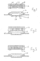
- the drawings show apparatus for removing an item of the shaped clay from a mould.
- the clay is in the form of an item of flatware such as a plate.
- the drawings show a permeable synthetic mould 10.
- the mould 10 is made from an acrylic bead and has an upper surface shaped to correspond to the upper surface of a plate.
- the mould 10 is mounted on a carrier 12 also made of acrylic.
- a piece of clay is located on the mould 10.
- the mould 10 is subsequently spun and a roller head (not shown) is used to form the piece of clay into a required shape 14.
- a former 16 is lowered onto the clay 14.
- the former 16 has a lower face as shown in the drawings, with a shape corresponding to the rear profile of the clay 14 such that the former 16 provides a close fit thereagainst.
- a downward force is then applied to the former 16 whilst suction is provided therethrough. Simultaneously air is blown through the mould 10 towards the clay 14.
- a plurality of passages 18 extend through the former 16 and connect with a chamber 20 which has an outlet 22 connectible to a suction pump or other source of reduced pressure.
- a chamber 24 is provided beneath the mould 10, between the mould 10 and the carrier 12 with an inlet 26 connectible to a source of above atmospheric pressure.
- the force applied to the former 16 is arranged to be slightly less than that applied to the clay 14 by air being blown through the mould 10.
- the force may be applied by a pneumatic cylinder or a resilient member.
- the mould 10 and former 16 can be separated with the clay 14 being held on the latter by the suction through the passages 18.
- the former 16 can then be turned over with the shaped clay 14 thereon to dry.
- the clay can be dried very quickly. Warm air may be blown through the empty mould 10 to condition same by removing any moisture or other materials.
- the former may be positioned with its shaped face pointing upwards such that the mould carrying shaped clay is lowered onto the former. In such an instance, suction is not required through the former to hold the clay thereon.
- the above described example uses an acrylic mould the invention is also readily applicable to plaster of paris moulds, or moulds made; from any suitable permeable material.
- the method can be used with different items of ware and different forming techniques.
- the method and apparatus readily lend themselves to automatic operation which could be arranged to provide a required mould and corresponding former as programmed by an operator.
- Means may be provided to indicate when the clay has been blown off the mould onto the former, perhaps by detecting a drop in back pressure in the mould.
- Said indication means may be connected to means for automatically separating the former and mould once this 'blowing off' has taken place.
Landscapes
- Engineering & Computer Science (AREA)
- Ceramic Engineering (AREA)
- Manufacturing & Machinery (AREA)
- Chemical & Material Sciences (AREA)
- Mechanical Engineering (AREA)
- Fluid Mechanics (AREA)
- Physics & Mathematics (AREA)
- Devices For Post-Treatments, Processing, Supply, Discharge, And Other Processes (AREA)
- Press-Shaping Or Shaping Using Conveyers (AREA)
- Moulds, Cores, Or Mandrels (AREA)
- Casting Or Compression Moulding Of Plastics Or The Like (AREA)
- Ceramic Products (AREA)
- Separation Using Semi-Permeable Membranes (AREA)
Claims (19)
- Verfahren zum Entfernen eines Stücks aus geformten Ton (14) aus einer Form (10), wobei das Verfahren Schritte aufweist zum Anordnen einer Formvorrichtung (16) an dem geformten Ton (14) an dessen zur Form entgegengesetzter Seite (10), wobei die Formvorrichtung (16) so geformt ist, dass sie im wesentlichen der Form des Tons (14) entspricht, um an ihr einen enganliegenden Sitz zu erzeugen; und Blasen eines Fluids durch die Form (10), um den geformten Ton (14) von der Form (10) weg und auf die Formvorrichtung (16) zu blasen, dadurch gekennzeichnet, dass eine Widerstandskraft an die Formvorrichtung (16) gegen den Ton (14) angelegt wird, wobei die Widerstandskraft geringfügig kleiner als die Kraft ist, die durch das durch die Form (10) geblasene Fluid angelegt wird.
- Verfahren nach Anspruch 1, dadurch gekennzeichnet, dass das Fluid Luft aufweist.
- Verfahren nach Anspruch 2, dadurch gekennzeichnet, dass die Luft erwärmt wird.
- Verfahren nach einem der vorhergehenden Ansprüche, dadurch gekennzeichnet, dass eine Saugwirkung durch die Formvorrichtung (16) angelegt wird, um den geformten Ton (14) nach dem Entfernen von der Form (10) daran zu halten.
- Verfahren nach einem der vorhergehenden Ansprüche, dadurch gekennzeichnet, dass nach dem Entfernen des geformten Tons (14) Luft durch die Form (10) geblasen wird, um die Form (10) zu konditionieren.
- Verfahren nach Anspruch 5, dadurch gekennzeichnet, dass die Luft erwärmt wird.
- Verfahren nach einem der vorhergehenden Ansprüche, dadurch gekennzeichnet, dass die Form (10) relativ zu der Formvorrichtung (16) gedreht wird, sobald Fluid durch die Form (10) geblasen wird, wodurch der Wasserfilm zwischen der Form (10) und dem Ton (14) geschert wird.
- Vorrichtung zum Entfernen eines Stücks aus geformtem Ton (14) von einer Form (10), dadurch gekennzeichnet, dass die Vorrichtung aufweist: eine Formvorrichtung (16), die an dem geformten Ton (14) an dessen entgegengesetzter Seite zur Form (10) anordenbar ist, wobei die Formvorrichtung (16) so geformt ist, dass sie im wesentlichen der Form des Tons (14) entspricht, um an ihr einen enganliegenden Sitz zu erzeugen; Mittel zum Blasen eines Fluids durch die Form (10), um den geformten Ton (14) von der Form (10) weg und auf die Formvorrichtung (16) zu blasen; und Mittel zum Anlegen einer Widerstandskraft an die Formvorrichtung (16) gegen den Ton (14), wobei die Widerstandskraft-Anlegungsmittel so angeordnet sind, dass sie eine Widerstandskraft ausüben, die geringfügig kleiner als die durch Blasmittel angelegte Kraft ist.
- Vorrichtung nach Anspruch 8, dadurch gekennzeichnet, dass die Widerstandskraft-Anlegungsmittel einen pneumatischen Zylinder aufweisen.
- Vorrichtung nach Anspruch 8, dadurch gekennzeichnet, dass die Widerstandskraft-Anlegungsmittel ein elastisches Glied, wie z.B. eine Feder, aufweisen.
- Vorrichtung nach einem der Ansprüche 8 bis 10, dadurch gekennzeichnet, dass erste Erfassungmittel vorgesehen sind, um zu erfassen, wann der geformte Ton (14) von der Form weggeblasen wurde.
- Vorrichtung nach Anspruch 11, dadurch gekennzeichnet, dass die ersten Erfassungsmittel zweite Erfassungsmittel aufweisen, um eine Verringerung des Rückstaudrucks in der Form (10) zu erfassen.
- Vorrichtung nach Anspruch 11 oder 12, dadurch gekennzeichnet, dass die ersten Erfassungsmittel mit Mitteln verbunden sind zum automatischen Trennen der Form (10) und der Formvorrichtung (16), wenn sich der geformte Ton (14) auf die letztere bewegt hat.
- Vorrichtung nach einem der Ansprüche 8 bis 13, dadurch gekennzeichnet, dass die Form (10) aus Acryl-Kunststoffmaterial besteht.
- Vorrichtung nach Anspruch 14, dadurch gekennzeichnet, dass die Form (10) aus einer Acryl-Perle bzw. einem Acryl-Wulst besteht.
- Vorrichtung nach Anspruch 14 oder 15, dadurch gekennzeichnet, dass das Kunststoffmaterial auf einem Träger montiert ist.
- Vorrichtung nach Anspruch 16, dadurch gekennzeichnet, dass der Träger aus Kunststoffmaterial, wie z.B. Acryl besteht.
- Vorrichtung nach Anspruch 16, dadurch gekennzeichnet, dass der Träger aus Metall besteht.
- Vorrichtung nach einem der Ansprüche 8 bis 13, dadurch gekennzeichnet, dass die Form (10) aus Modell-Gips besteht.
Applications Claiming Priority (3)
| Application Number | Priority Date | Filing Date | Title |
|---|---|---|---|
| GB9506940 | 1995-04-04 | ||
| GBGB9506940.7A GB9506940D0 (en) | 1995-04-04 | 1995-04-04 | Ware forming method and apparatus |
| PCT/GB1996/000775 WO1996031328A1 (en) | 1995-04-04 | 1996-04-02 | Ware forming method and apparatus |
Publications (2)
| Publication Number | Publication Date |
|---|---|
| EP0819044A1 EP0819044A1 (de) | 1998-01-21 |
| EP0819044B1 true EP0819044B1 (de) | 2001-06-27 |
Family
ID=10772488
Family Applications (1)
| Application Number | Title | Priority Date | Filing Date |
|---|---|---|---|
| EP96908253A Expired - Lifetime EP0819044B1 (de) | 1995-04-04 | 1996-04-02 | Verfahren und vorrichtung zum formen von porzellangegenständen |
Country Status (8)
| Country | Link |
|---|---|
| US (1) | US5935495A (de) |
| EP (1) | EP0819044B1 (de) |
| JP (1) | JP4068140B2 (de) |
| DE (1) | DE69613566T2 (de) |
| ES (1) | ES2159728T3 (de) |
| GB (1) | GB9506940D0 (de) |
| PT (1) | PT819044E (de) |
| WO (1) | WO1996031328A1 (de) |
Families Citing this family (7)
| Publication number | Priority date | Publication date | Assignee | Title |
|---|---|---|---|---|
| GB9618091D0 (en) | 1996-08-29 | 1996-10-09 | British Ceramic Res Ltd | Ware forming method and apparatus |
| GB2321615A (en) * | 1997-02-04 | 1998-08-05 | British Ceramic Res Ltd | Ware forming apparatus |
| EP1078726A2 (de) * | 1999-08-27 | 2001-02-28 | Nisshinbo Industries, Inc. | System und Verfahren zur Herstellung von Brenstoffzellenseparatoren und nach diesem Verfahren hergestellte Separatoren |
| EP2289339B1 (de) * | 2004-07-15 | 2016-04-20 | James D. Azzar | System zum Portionieren von Lebensmitteln |
| JP4529836B2 (ja) * | 2005-08-04 | 2010-08-25 | 高浜工業株式会社 | 陶磁器製品用の成形品の離型方法およびその離型装置 |
| US7867418B2 (en) * | 2007-09-24 | 2011-01-11 | Mars, Incorporated | Tool and apparatus for forming a moldable material |
| CN104290179B (zh) * | 2014-10-16 | 2017-02-22 | 福建省诺希科技园发展有限公司 | 一种抽滤注浆石膏模具的制造方法 |
Family Cites Families (9)
| Publication number | Priority date | Publication date | Assignee | Title |
|---|---|---|---|---|
| US2584109A (en) * | 1947-03-12 | 1952-02-05 | Ram Inc | Mold and method for molding ceramic ware |
| US2584110A (en) * | 1947-03-27 | 1952-02-05 | Ram Inc | Mold for pottery ware |
| US2632227A (en) * | 1951-01-12 | 1953-03-24 | Ram Inc | Method and apparatus for the release of ceramic ware from porous molds |
| DE1806959A1 (de) * | 1968-11-05 | 1970-06-11 | Will Dr Med Guenther | Dreharbeitsform und Transport der darauf hergestellten Formlinge aus Ton-,Keramik- und Porzellanmassen |
| DE2011909A1 (en) * | 1970-03-13 | 1971-11-18 | Will G | Parting pressure cast green ceramic slip castings |
| PL114601B1 (en) * | 1978-03-14 | 1981-02-28 | Inst Szkla I Ceramiki | Mould for manufacturing ceramic articles |
| US4413966A (en) * | 1981-06-26 | 1983-11-08 | Wallace Murray Corporation | Fluid-release mold and the method of manufacturing the same |
| EP0204683A3 (de) * | 1985-04-22 | 1989-02-01 | Meisel, Ronald M. Dipl. Ing. | Vorrichtung für Rollverfahren und entsprechend wirkende Verfahren zur Herstellung von keramischen Artikeln |
| GB9208772D0 (en) * | 1992-04-23 | 1992-06-10 | British Ceramic Res Ltd | Ware shaping apparatus |
-
1995
- 1995-04-04 GB GBGB9506940.7A patent/GB9506940D0/en active Pending
-
1996
- 1996-04-02 ES ES96908253T patent/ES2159728T3/es not_active Expired - Lifetime
- 1996-04-02 DE DE69613566T patent/DE69613566T2/de not_active Expired - Lifetime
- 1996-04-02 PT PT96908253T patent/PT819044E/pt unknown
- 1996-04-02 JP JP53007896A patent/JP4068140B2/ja not_active Expired - Fee Related
- 1996-04-02 WO PCT/GB1996/000775 patent/WO1996031328A1/en not_active Ceased
- 1996-04-02 US US08/930,293 patent/US5935495A/en not_active Expired - Lifetime
- 1996-04-02 EP EP96908253A patent/EP0819044B1/de not_active Expired - Lifetime
Also Published As
| Publication number | Publication date |
|---|---|
| US5935495A (en) | 1999-08-10 |
| ES2159728T3 (es) | 2001-10-16 |
| WO1996031328A1 (en) | 1996-10-10 |
| GB9506940D0 (en) | 1995-05-24 |
| DE69613566T2 (de) | 2002-04-25 |
| PT819044E (pt) | 2001-12-28 |
| DE69613566D1 (de) | 2001-08-02 |
| JP4068140B2 (ja) | 2008-03-26 |
| EP0819044A1 (de) | 1998-01-21 |
| JPH11511704A (ja) | 1999-10-12 |
Similar Documents
| Publication | Publication Date | Title |
|---|---|---|
| US5641372A (en) | Transferring apparatus and transferring method | |
| US4560339A (en) | Extracting system for fabricated objects formed by a thermo-forming machine | |
| US5935495A (en) | Ware forming method | |
| AR006030A1 (es) | Articulo para limpiar telas, metodo para limpieza, proceso de limpieza, refrescamiento y kit para el mismo | |
| AU4179400A (en) | Touch fasteners having portions with different properties and methods of making same | |
| JPH08506031A (ja) | バルーンに関する改良 | |
| JPH0811200A (ja) | 真空プレス積層成形方法及び装置 | |
| WO1996031328A9 (en) | Ware forming method and apparatus | |
| DE69718746D1 (de) | Vorrichtung zum Anbringen einer Folie an die Oberfläche eines Formwerkzeuges | |
| CA1320338C (fr) | Procede et dispositif pour l'habillage d'un objet au moyen d'au moins une piece souple | |
| JP2722069B2 (ja) | 印刷された弾性バンドの製造方法及び装置 | |
| EP0921918B1 (de) | Verfahren und vorrichtung zum formen von keramischen gegenständen | |
| US5783135A (en) | Demoulding apparatus | |
| US20060082018A1 (en) | Method and apparatus for making decorative laminates | |
| JP2994595B2 (ja) | 花弁の分離装置 | |
| US4381168A (en) | Method and apparatus for separating a layer of flexible material from a surface | |
| GB1560235A (en) | Device for removing labels from plastic housings | |
| EP0767742B1 (de) | Vorrichtung zum auftragen von abziehbildern | |
| GB2178450A (en) | Drying laundry by squeezing | |
| GB2321615A (en) | Ware forming apparatus | |
| JPH0753889Y2 (ja) | 複合自動加工装置 | |
| JPH05505568A (ja) | ウエア乾燥装置及びウエア乾燥方法並びに自動ウエア成形機 | |
| JPH0649333B2 (ja) | 真空成形装置および方法 | |
| ATE256012T1 (de) | Verfahren und vorrichtung zum trocknen von druckerzeugnissen | |
| JPS6399377A (ja) | 自動車用マツトのバツキング装置 |
Legal Events
| Date | Code | Title | Description |
|---|---|---|---|
| PUAI | Public reference made under article 153(3) epc to a published international application that has entered the european phase |
Free format text: ORIGINAL CODE: 0009012 |
|
| 17P | Request for examination filed |
Effective date: 19970925 |
|
| AK | Designated contracting states |
Kind code of ref document: A1 Designated state(s): DE ES FR GB IT PT SE |
|
| 17Q | First examination report despatched |
Effective date: 19990122 |
|
| GRAG | Despatch of communication of intention to grant |
Free format text: ORIGINAL CODE: EPIDOS AGRA |
|
| GRAG | Despatch of communication of intention to grant |
Free format text: ORIGINAL CODE: EPIDOS AGRA |
|
| GRAH | Despatch of communication of intention to grant a patent |
Free format text: ORIGINAL CODE: EPIDOS IGRA |
|
| GRAH | Despatch of communication of intention to grant a patent |
Free format text: ORIGINAL CODE: EPIDOS IGRA |
|
| GRAA | (expected) grant |
Free format text: ORIGINAL CODE: 0009210 |
|
| AK | Designated contracting states |
Kind code of ref document: B1 Designated state(s): DE ES FR GB IT PT SE |
|
| REF | Corresponds to: |
Ref document number: 69613566 Country of ref document: DE Date of ref document: 20010802 |
|
| ITF | It: translation for a ep patent filed | ||
| REG | Reference to a national code |
Ref country code: ES Ref legal event code: FG2A Ref document number: 2159728 Country of ref document: ES Kind code of ref document: T3 |
|
| ET | Fr: translation filed | ||
| REG | Reference to a national code |
Ref country code: PT Ref legal event code: SC4A Free format text: AVAILABILITY OF NATIONAL TRANSLATION Effective date: 20010918 |
|
| REG | Reference to a national code |
Ref country code: GB Ref legal event code: IF02 |
|
| PLBE | No opposition filed within time limit |
Free format text: ORIGINAL CODE: 0009261 |
|
| STAA | Information on the status of an ep patent application or granted ep patent |
Free format text: STATUS: NO OPPOSITION FILED WITHIN TIME LIMIT |
|
| 26N | No opposition filed | ||
| REG | Reference to a national code |
Ref country code: FR Ref legal event code: ST Effective date: 20101230 |
|
| REG | Reference to a national code |
Ref country code: FR Ref legal event code: RN |
|
| REG | Reference to a national code |
Ref country code: FR Ref legal event code: FC |
|
| PG25 | Lapsed in a contracting state [announced via postgrant information from national office to epo] |
Ref country code: FR Free format text: LAPSE BECAUSE OF NON-PAYMENT OF DUE FEES Effective date: 20100430 |
|
| PGFP | Annual fee paid to national office [announced via postgrant information from national office to epo] |
Ref country code: ES Payment date: 20120416 Year of fee payment: 17 |
|
| PGFP | Annual fee paid to national office [announced via postgrant information from national office to epo] |
Ref country code: GB Payment date: 20130320 Year of fee payment: 18 |
|
| PGFP | Annual fee paid to national office [announced via postgrant information from national office to epo] |
Ref country code: PT Payment date: 20130320 Year of fee payment: 18 |
|
| PGFP | Annual fee paid to national office [announced via postgrant information from national office to epo] |
Ref country code: DE Payment date: 20130418 Year of fee payment: 18 Ref country code: SE Payment date: 20130424 Year of fee payment: 18 |
|
| PGFP | Annual fee paid to national office [announced via postgrant information from national office to epo] |
Ref country code: IT Payment date: 20130419 Year of fee payment: 18 Ref country code: FR Payment date: 20130503 Year of fee payment: 18 |
|
| REG | Reference to a national code |
Ref country code: PT Ref legal event code: MM4A Free format text: LAPSE DUE TO NON-PAYMENT OF FEES Effective date: 20141002 |
|
| REG | Reference to a national code |
Ref country code: DE Ref legal event code: R119 Ref document number: 69613566 Country of ref document: DE |
|
| REG | Reference to a national code |
Ref country code: SE Ref legal event code: EUG |
|
| GBPC | Gb: european patent ceased through non-payment of renewal fee |
Effective date: 20140402 |
|
| REG | Reference to a national code |
Ref country code: FR Ref legal event code: ST Effective date: 20141231 |
|
| REG | Reference to a national code |
Ref country code: DE Ref legal event code: R119 Ref document number: 69613566 Country of ref document: DE Effective date: 20141101 |
|
| PG25 | Lapsed in a contracting state [announced via postgrant information from national office to epo] |
Ref country code: PT Free format text: LAPSE BECAUSE OF NON-PAYMENT OF DUE FEES Effective date: 20141002 Ref country code: GB Free format text: LAPSE BECAUSE OF NON-PAYMENT OF DUE FEES Effective date: 20140402 Ref country code: SE Free format text: LAPSE BECAUSE OF NON-PAYMENT OF DUE FEES Effective date: 20140403 Ref country code: DE Free format text: LAPSE BECAUSE OF NON-PAYMENT OF DUE FEES Effective date: 20141101 |
|
| PG25 | Lapsed in a contracting state [announced via postgrant information from national office to epo] |
Ref country code: FR Free format text: LAPSE BECAUSE OF NON-PAYMENT OF DUE FEES Effective date: 20140430 |
|
| PG25 | Lapsed in a contracting state [announced via postgrant information from national office to epo] |
Ref country code: IT Free format text: LAPSE BECAUSE OF NON-PAYMENT OF DUE FEES Effective date: 20140402 |
|
| REG | Reference to a national code |
Ref country code: ES Ref legal event code: FD2A Effective date: 20150527 |
|
| PG25 | Lapsed in a contracting state [announced via postgrant information from national office to epo] |
Ref country code: ES Free format text: LAPSE BECAUSE OF NON-PAYMENT OF DUE FEES Effective date: 20140403 |