EP0819331B1 - Elektromechanische steuereinheit für verstelleinrichtungen in kraftfahrzeugen - Google Patents
Elektromechanische steuereinheit für verstelleinrichtungen in kraftfahrzeugen Download PDFInfo
- Publication number
- EP0819331B1 EP0819331B1 EP96909033A EP96909033A EP0819331B1 EP 0819331 B1 EP0819331 B1 EP 0819331B1 EP 96909033 A EP96909033 A EP 96909033A EP 96909033 A EP96909033 A EP 96909033A EP 0819331 B1 EP0819331 B1 EP 0819331B1
- Authority
- EP
- European Patent Office
- Prior art keywords
- switch
- control unit
- electronics
- electromechanical control
- unit according
- Prior art date
- Legal status (The legal status is an assumption and is not a legal conclusion. Google has not performed a legal analysis and makes no representation as to the accuracy of the status listed.)
- Expired - Lifetime
Links
- 238000004519 manufacturing process Methods 0.000 description 3
- 230000005489 elastic deformation Effects 0.000 description 2
- 238000009434 installation Methods 0.000 description 2
- 230000010354 integration Effects 0.000 description 2
- 230000004308 accommodation Effects 0.000 description 1
- 230000000712 assembly Effects 0.000 description 1
- 238000000429 assembly Methods 0.000 description 1
- 230000005540 biological transmission Effects 0.000 description 1
- 238000010276 construction Methods 0.000 description 1
- 238000001035 drying Methods 0.000 description 1
- 125000000524 functional group Chemical group 0.000 description 1
- 238000010438 heat treatment Methods 0.000 description 1
- 230000003993 interaction Effects 0.000 description 1
- 230000006386 memory function Effects 0.000 description 1
Images


Classifications
-
- E—FIXED CONSTRUCTIONS
- E05—LOCKS; KEYS; WINDOW OR DOOR FITTINGS; SAFES
- E05F—DEVICES FOR MOVING WINGS INTO OPEN OR CLOSED POSITION; CHECKS FOR WINGS; WING FITTINGS NOT OTHERWISE PROVIDED FOR, CONCERNED WITH THE FUNCTIONING OF THE WING
- E05F15/00—Power-operated mechanisms for wings
- E05F15/60—Power-operated mechanisms for wings using electrical actuators
- E05F15/603—Power-operated mechanisms for wings using electrical actuators using rotary electromotors
- E05F15/665—Power-operated mechanisms for wings using electrical actuators using rotary electromotors for vertically-sliding wings
- E05F15/689—Power-operated mechanisms for wings using electrical actuators using rotary electromotors for vertically-sliding wings specially adapted for vehicle windows
- E05F15/697—Motor units therefor, e.g. geared motors
-
- H—ELECTRICITY
- H02—GENERATION; CONVERSION OR DISTRIBUTION OF ELECTRIC POWER
- H02K—DYNAMO-ELECTRIC MACHINES
- H02K11/00—Structural association of dynamo-electric machines with electric components or with devices for shielding, monitoring or protection
-
- B—PERFORMING OPERATIONS; TRANSPORTING
- B60—VEHICLES IN GENERAL
- B60J—WINDOWS, WINDSCREENS, NON-FIXED ROOFS, DOORS, OR SIMILAR DEVICES FOR VEHICLES; REMOVABLE EXTERNAL PROTECTIVE COVERINGS SPECIALLY ADAPTED FOR VEHICLES
- B60J7/00—Non-fixed roofs; Roofs with movable panels, e.g. rotary sunroofs
- B60J7/02—Non-fixed roofs; Roofs with movable panels, e.g. rotary sunroofs of sliding type, e.g. comprising guide shoes
- B60J7/04—Non-fixed roofs; Roofs with movable panels, e.g. rotary sunroofs of sliding type, e.g. comprising guide shoes with rigid plate-like element or elements, e.g. open roofs with harmonica-type folding rigid panels
- B60J7/057—Driving or actuating arrangements e.g. manually operated levers or knobs
- B60J7/0573—Driving or actuating arrangements e.g. manually operated levers or knobs power driven arrangements, e.g. electrical
-
- H—ELECTRICITY
- H02—GENERATION; CONVERSION OR DISTRIBUTION OF ELECTRIC POWER
- H02K—DYNAMO-ELECTRIC MACHINES
- H02K11/00—Structural association of dynamo-electric machines with electric components or with devices for shielding, monitoring or protection
- H02K11/30—Structural association with control circuits or drive circuits
- H02K11/38—Control circuits or drive circuits associated with geared commutator motors of the worm-and-wheel type
-
- E—FIXED CONSTRUCTIONS
- E05—LOCKS; KEYS; WINDOW OR DOOR FITTINGS; SAFES
- E05Y—INDEXING SCHEME ASSOCIATED WITH SUBCLASSES E05D AND E05F, RELATING TO CONSTRUCTION ELEMENTS, ELECTRIC CONTROL, POWER SUPPLY, POWER SIGNAL OR TRANSMISSION, USER INTERFACES, MOUNTING OR COUPLING, DETAILS, ACCESSORIES, AUXILIARY OPERATIONS NOT OTHERWISE PROVIDED FOR, APPLICATION THEREOF
- E05Y2900/00—Application of doors, windows, wings or fittings thereof
- E05Y2900/50—Application of doors, windows, wings or fittings thereof for vehicles
- E05Y2900/53—Type of wing
- E05Y2900/542—Roof panels
-
- E—FIXED CONSTRUCTIONS
- E05—LOCKS; KEYS; WINDOW OR DOOR FITTINGS; SAFES
- E05Y—INDEXING SCHEME ASSOCIATED WITH SUBCLASSES E05D AND E05F, RELATING TO CONSTRUCTION ELEMENTS, ELECTRIC CONTROL, POWER SUPPLY, POWER SIGNAL OR TRANSMISSION, USER INTERFACES, MOUNTING OR COUPLING, DETAILS, ACCESSORIES, AUXILIARY OPERATIONS NOT OTHERWISE PROVIDED FOR, APPLICATION THEREOF
- E05Y2900/00—Application of doors, windows, wings or fittings thereof
- E05Y2900/50—Application of doors, windows, wings or fittings thereof for vehicles
- E05Y2900/53—Type of wing
- E05Y2900/55—Windows
-
- H—ELECTRICITY
- H02—GENERATION; CONVERSION OR DISTRIBUTION OF ELECTRIC POWER
- H02K—DYNAMO-ELECTRIC MACHINES
- H02K7/00—Arrangements for handling mechanical energy structurally associated with dynamo-electric machines, e.g. structural association with mechanical driving motors or auxiliary dynamo-electric machines
- H02K7/10—Structural association with clutches, brakes, gears, pulleys or mechanical starters
- H02K7/116—Structural association with clutches, brakes, gears, pulleys or mechanical starters with gears
- H02K7/1163—Structural association with clutches, brakes, gears, pulleys or mechanical starters with gears where at least two gears have non-parallel axes without having orbital motion
- H02K7/1166—Structural association with clutches, brakes, gears, pulleys or mechanical starters with gears where at least two gears have non-parallel axes without having orbital motion comprising worm and worm-wheel
Definitions
- the invention relates to an electromechanical control unit for adjusting devices in Motor vehicles according to the preamble of claim 1 (WO-A-90/10558) and can be particularly Use advantageously in connection with a window regulator drive in a vehicle door.
- WO 91/01060 describes a drive unit for an electric motor Window lifters known, consisting of a motor with a gear and a control and Control electronics exist.
- the gear housing is designed so that the control and control electronics can then be used.
- About one at the electronics attached plug stands the drive unit with a remote switch for the generation of control signals and a voltage source in connection.
- the drive unit described represents a relatively compact assembly group, however only the electrically conductive connection between this unit and the switch block be produced in the course of completing the motor vehicle door. This is causing Compared to the separately designed modular construction, increased assembly effort. A common pre-check of the drive unit, including the switches, is not possible.
- DE-PS 36 09 609 C2 one of an electronic module, plug elements and Operating switches existing assembly unit described in a motor vehicle door to be installed and via a cable harness with functional elements, for example a mirror adjustment, a central locking system and / or a window regulator drive in Connection is established.
- the housing of this assembly unit is stored either in part of the Interior door trim (e.g. armrest) or on the inner door panel.
- the invention has for its object the degree of integration of electrical and electronic assemblies for adjustment devices and other functional groups in To increase motor vehicles and to reduce the manufacturing and testing costs.
- the object is characterized by the features of Claim 1 solved.
- the subclaims describe preferred variants of the Invention.
- the electromechanical drive, the electronics unit and at least one switch is a pre-testable modular unit.
- This unit requires the spatial conditions of the drive connected adjustment device on the one hand and the location of the generation of Control signals necessary switches to coordinate on the other hand. It is on it to ensure that the forces emanating from the electromechanical drive and thus connected elastic deformations of load-bearing parts no or only insignificant slight movements are transmitted to the switches. This can be done, for example an elastic, floating connection between the switch and the electronics unit can be achieved.
- the switch should have a cover, such as the Door lining, be positively engaged.
- the switch also be connected to the electronics unit via a flexible electrical line, wherein again the switch is carried by a cover or the like.
- the modular unit carries at least one another switch that is connected to another electrical functional element stands.
- This can be, for example, an electric seat adjustment or mirror adjustment or heating. This allows the effort for separate installation of the second Save the switch.
- the power supply of the modular unit as well as the electrical Connection of the additional switch to the further electrical functional element can be implemented via a common serial interface. To expand the modular unit with an additional switch is between this and the electronics an electrical connector is provided, which simultaneously with the mechanical Connection of the two parts is made.
- Another variant of the invention provides for the switch to control at least to arrange another electrical functional element in a separate housing and to have its own electrical output. So there is a connection of the switch with the modular unit is only mechanical. So much for the rest electrical functional element, for example an electrical seat adjustment, a separate Control electronics should have, so this can either in the housing of the assigned switch or near the functional unit (the seat adjustment system) be arranged. In the event that both electrical functional elements, for example the Window regulator and seat adjustment, equipped with an electronic control unit would not only be the spatial accommodation of these electronics common housing, but also their functional union advantageous. Perhaps necessary relays for switching power currents can be connected to one of the modular unit can be housed at remote location.
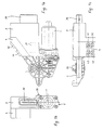
- FIGS. 1a to 1c show on the basis of a electromechanical control unit for an electrically powered window lifter Minimal variant of the invention. It comprises only one electronics 3 with only one Switch block 4 for an electromechanical drive 1,2. It forms the side arranged switch block 4 with the housing of the electronics 3 one unit.
- the single ones Push button switches 41, 42, 43, 44 for actuating the four side windows of a motor vehicle Part of a driver's drive and control unit.
- that is more advantageous Production of the modular unit according to the invention using a separate, switch blocks 4 which can be connected to the electronics 3 in order to reduce the number of variants So can only by replacing the switch block 4 shown by one for the A new variant can be easily generated in the rear of the specific switch block.
- the electronics 3 and also the motor 1 are electrically connected via a plug connection 30 Energy supplied. Signals, for example the switching states of the Ignition lock or the locked state of the doors, via this connector 30 be transmitted.
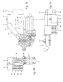
- the variant of the invention according to FIGS. 2a to 2c additionally has a switch block 5 for an electric seat adjustment, but otherwise agrees the unit described above.
- a switch block 5 for the seat adjustment In the side wall of the electronics 3 is below the switching block 4 for the window lifter a connector 31, through which Switch block 5 for the seat adjustment can be connected to the electronics 3. in the The present case is a switch 5 for a seat adjustment Memory function, by pressing the buttons 51, 52 the associated programmed seating positions can be approached.
- the seat cushion, backrest and headrest stand to symbolize the seat Key combination 53, 54, 55 available.
- the two switch blocks 4, 5 have a common one serial interface.
- the electronics 3 can control the window regulator as well as the Take over seat adjustment
- the switch block could be a separate one Include seat electronics, which via the plug connection 31 with the serial interface 30 communicates. So the connector 31 is chosen accordingly Optional equipment level of the vehicle.
- FIGS. 3a to 3c Another optionally available variant is shown in FIGS. 3a to 3c.
- the modular electromechanical control unit completed with a switch block 5, the is assigned to a seat adjustment without memory electronics.
- the Switch block 5 via which the power current is switched, a separate one Plug connection 50, to which the cable of the seat adjustment is connected.
- the optional plug connection 31 for forwarding To use signals (for example from the ignition lock) that the window electronics 3 are supplied via the connector 30.
- the modular unit in FIG. 4 has a particularly high degree of integration. she each has a connector block 4 ', 5', 6 'for the window regulator drive 4', for the seat adjustment 5 'and for the mirror adjustment 6', this via plug connections 31 ', 310', 32 ', 320 ', 33', 330 'are contacted with common electronics 3'. All for them Power supply and other signal exchange necessary contacts are over the connector 30 realized.
- This embodiment makes a large number optional Variants that are inexpensive to produce are available.
- FIGS. 5a to 5d uses a flexible one Ribbon cable 46 between the electronics 3 "and the switch block 4" and thus offers particularly good conditions for compensating for relative movements. While the rigidly connected parts (motor 1, gear 2 and electronics 3 ") on the inner door panel 7 or a carrier plate are mounted, the switch block 4 "of the Door lining 8 worn. A cover 40 inserted into the door interior trim 8 has a tab 400 directed downwards into the door interior, with recesses, in the projections 47, 48 of the switch housing 4 "can be clipped, which is a simple Fixation of the switch block 4 "on the inner door panel 8 enables (see Figures 5b and 5c). Relative movements between the parts 1,2,3 "fastened to the inner door panel 7 and the switch block 4 "are easily from the flexible ribbon cable 46th balanced.
- Figure 5a shows the modular unit according to the invention in its transport position in front of the Installation in the door.
- the housing of the electronics 3 "carries a fork-shaped upwards open transport bracket 45b into which a fit, bolt-like transport bracket 45a of the switch block 4 "can intervene.
- the transport position is selected so that at a during the assembly upward movement of the switch block 4 "immediately after loosening the transport bracket 45a, 45b its attachment to the panel 40 and thus takes place on the inner door panel 8.
- FIG. 5d The top view of the switch area of a motor vehicle door designed for the driver shows Figure 5d. Through the panel 4 are buttons for operating four window regulators accessible.
Landscapes
- Engineering & Computer Science (AREA)
- Power Engineering (AREA)
- Mechanical Engineering (AREA)
- Power-Operated Mechanisms For Wings (AREA)
- Window Of Vehicle (AREA)
- Automobile Manufacture Line, Endless Track Vehicle, Trailer (AREA)
Description
- Figur 1
- zeigt verschiedene Ansichten einer für einen Fensterheber vorgesehenen elektromechanischen Steuereinheit.
- Figur 1a
- Seitenansicht;
- Figur 1b
- steckerseitige Ansicht;
- Figur 1c
- Draufsicht;
- Figur 2a bis 2c
- modulare Einheit gemäß den Figuren 1a bis 1c in verschiedenen Ansichten, jedoch erweitert durch einen Schalter für eine elektrisch betriebene Sitzverstellung;
- Figur 3a bis 3c
- modulare Einheit gemäß den Figuren 1a bis 1c in verschiedenen Ansichten, erweitert durch einen Schalter mit separatem elektrischen Eingang für eine elektrisch betriebene Sitzverstellung;
- Figur 4
- schematische Darstellung einer elektromechanischen Steuereinheit für einen elektrisch betriebenen Fensterheber und zusätzlichen Schalterblöcken für eine Elektronische Sitzmemory sowie eine elektrische Spiegelverstellung;
- Figur 5a
- elektromechanische Steuereinheit mit Flachbandkabelverbindung zwischen Elektronik und Schalterblock in Transportposition;
- Figur 5b
- Schnittdarstellung durch die elektromechanische Steuereinheit im Einbauzustand in einer Kraftfahrzeugtür;
- Figur 5c
- Seitenansicht der elektromechanischen Steuereinheit im Einbauzustand;
- Figur 5d
- Draufsicht auf den Schalterbereich der Kraftfahrzeugtür.
- 1 -
- Motor
- 2 -
- Getriebe
- 20 -
- Antriebsachse
- 3 -
- Elektronik
- 3' -
- Elektronik
- 3" -
- Elektronik
- 30 -
- Steckverbindung
- 31' -
- optionale Steckverbindung für Sitzverstellschalter
- 32' -
- optionale Steckverbindung für Spiegelverstellschalter
- 33' -
- optionale Steckverbindung für Fensterheberschalter
- 310' -
- Steckverbindung des Sitzverstellschalters
- 320' -
- Steckverbindung des Spiegelverstellschalters
- 330' -
- Steckverbindung des Fensterheberschalters
- 4 -
- Schalterblock der Fensterheberverstellung
- 4' -
- Schalterblock der Sitzverstellung
- 4" -
- Schalterblock für Fensterheber
- 40 -
- Blende für Schalterblock
- 41 -
- Tastschalter für fahrerseitiges Fenster
- 42 -
- Tastschalter für beifahrerseitiges Fenster
- 43 -
- Tastschalter für fahrerseitiges Fondfenster
- 44 -
- Tastschalter für beifahrerseitges Fondfenster
- 45a -
- Transporthalterung
- 45b -
- Transporthalterung
- 47 -
- Vorsprung des Schaltergehäuses
- 48 -
- Vorsprung des Schaltergehäuses
- 400 -
- Lasche der Blende mit Ausnehmung
- 5 -
- Schalterblock der Sitzverstellung
- 5' -
- Schalterblock der Spiegelverstellung
- 51 -
- Steckverbindung
- 52 -
- Memorytaster für erste gespeicherte Sitzposition
- 53 -
- Memorytaster für zweite gespeicherte Sitzposition
- 53 -
- Tastschatler für Sitzkissenverstellung
- 54 -
- Tastschalter für Lehnenverstellung
- 55
- Tastschalter für Kopfstützenverstellung
- 6' -
- Schalterblock des Fensterhebers
- 7 -
- Trägerplatte/Türinnenblech
- 8 -
- Türinnenverkleidung
Claims (11)
- Elektromechanische Steuereinheit für Verstelleinrichtungen in Kraftfahrzeugen, insbesondere für Fensterheber, bestehend aus einem elektromechanischen Antrieb mit Elektromotor (1) und Getriebe (2), einer mit dem Elektromotor in Wirkverbindung stehenden Elektronikeinheit (3), mindestens einem mit der Elektronikeinheit in Wirkverbindung stehenden Schalter (4) zur Auslösung von Steuerbefehlen sowie mindestens einem weiteren Schalter (5, 6) zur Steuerung mindestens eines weiteren Funktionselements, z.B. einer elektrischen Sitz- oder Spiegelverstellung,
dadurch gekennzeichnet,
daß die Schalter (4, 4', 4", 5, 5', 6') an einem den elektromechanischen Antrieb (1, 2) und die Elektronikeinheit (3, 3', 3") umfassenden Gehäuse mechanisch festlegbar und elektrisch koppelbar sind, bevor diese modulare Einheit in ein übergeordnetes Funktionssystem eingebaut ist, wobei der Schalter (5, 5') zur Steuerung des weiteren Funktionselements über einen elektrischen Steckkontakt (31, 31', 310') mit der Elektronikeinheit (3, 3', 3") in Verbindung steht und mit dieser über eine gemeinsame serielle Schnittstelle verfügt. - Elektromechanische Steuereinheit nach Anspruch 1, dadurch gekennzeichnet, daß der Schalter (4') oder Teile des Schalters mit einer Abdeckung (40) formschlüssig in Eingriff stehen, und daß der Schalter (4') mit der Elektronikeinheit (3') in elastischer, schwimmender Verbindung steht.
- Elektromechanische Steuereinheit nach Anspruch 1, dadurch gekennzeichnet, daß der Schalter (4") oder Teile des Schalters mit einer Abdeckung (40) formschlüssig in Eingriff stehen, und daß der Schalter (4") mit der Elektronikeinheit (3") über eine flexible elektrische Leitung (46) in Verbindung steht.
- Elektromechanische Steuereinheit nach einem der vorangehenden Ansprüche, dadurch gekennzeichnet, daß der Schalter (5, 5', 6') zur Steuerung von mindestens einem weiteren elektrischen Funktionselement in einem separaten Gehäuse angeordnet und wahlweise mit der elektromechanischen Steuereinheit kombinierbar ist.
- Elektromechanische Steuereinheit nach einem der vorangehenden Ansprüche, dadurch gekennzeichnet, daß der Schalter eine separate elektrische Verbindung (50) zu einem Sitzverstellsystem aufweist.
- Elektromechanische Steuereinheit nach Anspruch 1, dadurch gekennzeichnet, daß eine separate Sitzelektronik vorgesehen ist, die entweder mit dem zugeordneten Schalter (5, 5') oder dem elektrischen Antrieb eine Einheit bildet.
- Elektromechanische Steuereinheit nach Anspruch 1, dadurch gekennzeichnet, daß eine Fensterheberelektronik und eine Sitzelektronik eine Einheit bilden und das gegebenenfalls notwendige Relais der Sitzverstellung in der Nähe des zugehörigen Antriebs oder in einem separaten Gehäuse angeordnet ist.
- Elektromechanische Steuereinheit nach Anspruch 1, dadurch gekennzeichnet, daß das Elektronikgehäuse im Bereich des Steckkontaktes (31, 31') ein entnehmbares Verschlußteil aufweist, so daß bei Bedarf eine Steckverbindung zwischen dem Sitzschalter und der Elektronik (3, 3') hergestellt werden kann.
- Elektromechanische Steuereinheit nach Anspruch 8, dadurch gekennzeichnet, daß das Verschlußteil einem durch Sollbruchstellen gebildeten Bereich entspricht und aus dem Gehäuse ausbrechbar ist.
- Elektromechanische Steuereinheit nach einem der vorangehenden Ansprüche, dadurch gekennzeichnet, daß der Schalter zum Steuern eines Fensterhebers in einer im wesentlichen horizontalen oder in Fahrtrichtung ansteigend verlaufenden Fläche und der Schalter zur Ansteuerung einer Sitzverstellung in einer im wesentlichen vertikal ausgerichteten, in den Fahrgastinnenraum weisenden Fläche der Türinnenverkleidung angeordnet ist.
- Elektromechanische Steuereinheit nach Anspruch 1, dadurch gekennzeichnet, daß diese auf einer Trägerplatte eines Türmoduls auf der Seite des Trockenraums vormontiert ist.
Applications Claiming Priority (3)
| Application Number | Priority Date | Filing Date | Title |
|---|---|---|---|
| DE19513085 | 1995-04-07 | ||
| DE19513085A DE19513085C1 (de) | 1995-04-07 | 1995-04-07 | Elektromechanische Steuereinheit für Verstelleinrichtungen in Kraftfahrzeugen |
| PCT/DE1996/000631 WO1996031935A1 (de) | 1995-04-07 | 1996-04-03 | Elektromechanische steuereinheit für verstelleinrichtungen in kraftfahrzeugen |
Publications (2)
| Publication Number | Publication Date |
|---|---|
| EP0819331A1 EP0819331A1 (de) | 1998-01-21 |
| EP0819331B1 true EP0819331B1 (de) | 1999-02-03 |
Family
ID=7759064
Family Applications (1)
| Application Number | Title | Priority Date | Filing Date |
|---|---|---|---|
| EP96909033A Expired - Lifetime EP0819331B1 (de) | 1995-04-07 | 1996-04-03 | Elektromechanische steuereinheit für verstelleinrichtungen in kraftfahrzeugen |
Country Status (10)
| Country | Link |
|---|---|
| EP (1) | EP0819331B1 (de) |
| JP (1) | JPH11503598A (de) |
| KR (1) | KR100376142B1 (de) |
| CN (1) | CN1062988C (de) |
| AR (1) | AR001554A1 (de) |
| BR (1) | BR9604848A (de) |
| DE (2) | DE19513085C1 (de) |
| ES (1) | ES2130809T3 (de) |
| MX (1) | MX9707625A (de) |
| WO (1) | WO1996031935A1 (de) |
Families Citing this family (9)
| Publication number | Priority date | Publication date | Assignee | Title |
|---|---|---|---|---|
| DE19707850C1 (de) * | 1997-02-27 | 1998-03-12 | Brose Fahrzeugteile | Motor-Getriebe-Einheit für Verstelleinrichtungen in Kraftfahrzeugen |
| DE19849837C2 (de) * | 1998-10-29 | 2003-02-20 | Webasto Vehicle Sys Int Gmbh | Tandem-Antriebsvorrichtung für ein verstellbares Fahrzeugdach |
| JP3844178B2 (ja) * | 1999-07-05 | 2006-11-08 | 矢崎総業株式会社 | 自動車ドアの回路接続構造 |
| DE10144476A1 (de) * | 2001-09-10 | 2003-03-27 | Nacam Deutschland Gmbh | Kraftfahrzeuglenksäuleneinheit mit verstellbarer Lenksäule |
| DE20215282U1 (de) * | 2002-10-04 | 2003-12-24 | Brose Fahrzeugteile Gmbh & Co. Kommanditgesellschaft, Coburg | Kraftfahrzeugtür, sowie Steuergerät und Baugruppe eines Kraftfahrzeugs |
| DE10354594B4 (de) * | 2003-11-21 | 2005-08-25 | Abb Technology Ag | Antriebseinheit eines Schaltgerätes einer gasisolierten Schaltanlage und Baukastensystem zur Bildung einer Antriebseinheit |
| DE102004028334B4 (de) | 2004-06-11 | 2006-06-14 | Siemens Ag | Sensoranordnung mit Haltebrücke für einen Stecker |
| EP1947981B1 (de) * | 2005-10-18 | 2017-03-15 | Linak A/S | Möbelstück, insbesondere ein sitz-/stehtisch |
| FR2982542B1 (fr) * | 2011-11-16 | 2013-12-20 | Peugeot Citroen Automobiles Sa | Glissiere de siege |
Family Cites Families (7)
| Publication number | Priority date | Publication date | Assignee | Title |
|---|---|---|---|---|
| US2921783A (en) * | 1957-09-25 | 1960-01-19 | Alan W Wentz | Electrical window operator unit |
| DE3609609A1 (de) * | 1986-03-21 | 1987-10-01 | Audi Ag | Mehrwandige fahrzeugtuer eines kraftfahrzeuges |
| JPH0659780B2 (ja) * | 1987-02-13 | 1994-08-10 | 株式会社大井製作所 | 車両用サンル−フの駆動装置 |
| IT216963Z2 (it) * | 1989-03-07 | 1991-10-21 | Roltra Spa | Dispositivo a tasti di comando ma nuale |
| DE9006924U1 (de) * | 1989-07-11 | 1990-08-23 | Brose Fahrzeugteile GmbH & Co KG, 8630 Coburg | Elektromotorischer Fensterheber |
| DE4323946C2 (de) * | 1993-07-16 | 1999-02-25 | Webasto Karosseriesysteme | Antriebsvorrichtung für ein verstellbares Fahrzeugteil |
| DE4430700A1 (de) * | 1994-08-30 | 1996-03-07 | Teves Gmbh Alfred | In Motordeckel integrierter Schalter |
-
1995
- 1995-04-07 DE DE19513085A patent/DE19513085C1/de not_active Expired - Fee Related
-
1996
- 1996-04-03 DE DE59601266T patent/DE59601266D1/de not_active Expired - Fee Related
- 1996-04-03 EP EP96909033A patent/EP0819331B1/de not_active Expired - Lifetime
- 1996-04-03 CN CN96193128A patent/CN1062988C/zh not_active Expired - Fee Related
- 1996-04-03 ES ES96909033T patent/ES2130809T3/es not_active Expired - Lifetime
- 1996-04-03 BR BR9604848A patent/BR9604848A/pt not_active IP Right Cessation
- 1996-04-03 JP JP8529863A patent/JPH11503598A/ja active Pending
- 1996-04-03 AR AR33605596A patent/AR001554A1/es unknown
- 1996-04-03 WO PCT/DE1996/000631 patent/WO1996031935A1/de not_active Ceased
- 1996-04-03 KR KR1019970707020A patent/KR100376142B1/ko not_active Expired - Fee Related
-
1997
- 1997-10-03 MX MX9707625A patent/MX9707625A/es not_active IP Right Cessation
Also Published As
| Publication number | Publication date |
|---|---|
| DE19513085C1 (de) | 1996-04-04 |
| EP0819331A1 (de) | 1998-01-21 |
| ES2130809T3 (es) | 1999-07-01 |
| KR100376142B1 (ko) | 2003-06-09 |
| BR9604848A (pt) | 1998-06-16 |
| MX9707625A (es) | 1998-06-30 |
| JPH11503598A (ja) | 1999-03-26 |
| WO1996031935A1 (de) | 1996-10-10 |
| CN1062988C (zh) | 2001-03-07 |
| DE59601266D1 (de) | 1999-03-18 |
| AR001554A1 (es) | 1997-11-26 |
| KR19980703621A (ko) | 1998-12-05 |
| CN1181162A (zh) | 1998-05-06 |
Similar Documents
| Publication | Publication Date | Title |
|---|---|---|
| DE19815843B4 (de) | Vorrichtung zur Energie- und Signalübertragung zischen Teilen eines Fahrzeugs | |
| DE4029890C2 (de) | Rückblick-Einrichtung für Kraftfahrzeuge | |
| EP1009647B1 (de) | Fahrzeugtür | |
| DE19622256A1 (de) | Sitzkombinationsschalter | |
| DE69502202T2 (de) | Wahlweise steckbare speichergruppe für stellantrieb | |
| EP0819331B1 (de) | Elektromechanische steuereinheit für verstelleinrichtungen in kraftfahrzeugen | |
| DE3609609C2 (de) | ||
| DE19641898C1 (de) | Nutzungsberechtigungssystem | |
| DE19951916C1 (de) | Elektronische Steuerungseinrichtung zur Ansteuerung elektrischer Aggregate von Kraftfahrzeugtüren mit unterschiedlicher Ausstattung | |
| DE102006007802A1 (de) | Schalterbaugruppe für Fahrzeuge | |
| DE102005035454A1 (de) | Elastomerischer Fahrzeugsteuerschalter | |
| DE102006004373B4 (de) | Elastometrischer Fahrzeug-Steuerschalter | |
| DE102004042543B4 (de) | Steuersystem für elektrisch angetriebene Fenster | |
| DE3930153A1 (de) | Verkabelungssystem fuer fahrzeuge | |
| DE102005051423B3 (de) | Crashaktive Kopfstütze | |
| US6565142B1 (en) | Vehicle door inner trim panel assembly including electrical control panel | |
| DE69015625T2 (de) | Von hand zu betätigender druckknopf. | |
| DE3788740T2 (de) | Steuerungseinrichtung für vielfache Schalter. | |
| EP1797342B1 (de) | Taste mit seilzug | |
| EP1199218B1 (de) | Elektronischer Spiegelschalter und Aussenspiegel mit einem solchen Spiegelschalter | |
| DE10060981A1 (de) | Betätigungseinrichtung zum Auslösen wenigstens einer Funktion eines Kraftfahrzeugs | |
| DE4418902C2 (de) | Elektronisches Schließsystem für Kraftfahrzeuge | |
| DE3917637C2 (de) | Mehrfachtastschalter | |
| DE102023201594A1 (de) | Komforteinrichtung für ein Fahrzeug sowie Fahrzeug mit einer solchen Komforteinrichtung | |
| EP0503409A2 (de) | Schaltungsanordung für die Steuerung des Öffnungs- und Schliessvorganges von Fensterhebern in Kraftfahrzeugen |
Legal Events
| Date | Code | Title | Description |
|---|---|---|---|
| PUAI | Public reference made under article 153(3) epc to a published international application that has entered the european phase |
Free format text: ORIGINAL CODE: 0009012 |
|
| 17P | Request for examination filed |
Effective date: 19971030 |
|
| AK | Designated contracting states |
Kind code of ref document: A1 Designated state(s): DE ES FR GB IT SE |
|
| GRAG | Despatch of communication of intention to grant |
Free format text: ORIGINAL CODE: EPIDOS AGRA |
|
| GRAG | Despatch of communication of intention to grant |
Free format text: ORIGINAL CODE: EPIDOS AGRA |
|
| GRAH | Despatch of communication of intention to grant a patent |
Free format text: ORIGINAL CODE: EPIDOS IGRA |
|
| 17Q | First examination report despatched |
Effective date: 19980708 |
|
| GRAH | Despatch of communication of intention to grant a patent |
Free format text: ORIGINAL CODE: EPIDOS IGRA |
|
| GRAA | (expected) grant |
Free format text: ORIGINAL CODE: 0009210 |
|
| AK | Designated contracting states |
Kind code of ref document: B1 Designated state(s): DE ES FR GB IT SE |
|
| REF | Corresponds to: |
Ref document number: 59601266 Country of ref document: DE Date of ref document: 19990318 |
|
| ET | Fr: translation filed | ||
| ITF | It: translation for a ep patent filed | ||
| GBT | Gb: translation of ep patent filed (gb section 77(6)(a)/1977) |
Effective date: 19990423 |
|
| REG | Reference to a national code |
Ref country code: ES Ref legal event code: FG2A Ref document number: 2130809 Country of ref document: ES Kind code of ref document: T3 |
|
| PLBE | No opposition filed within time limit |
Free format text: ORIGINAL CODE: 0009261 |
|
| STAA | Information on the status of an ep patent application or granted ep patent |
Free format text: STATUS: NO OPPOSITION FILED WITHIN TIME LIMIT |
|
| 26N | No opposition filed | ||
| REG | Reference to a national code |
Ref country code: GB Ref legal event code: IF02 |
|
| PGFP | Annual fee paid to national office [announced via postgrant information from national office to epo] |
Ref country code: SE Payment date: 20030404 Year of fee payment: 8 |
|
| PG25 | Lapsed in a contracting state [announced via postgrant information from national office to epo] |
Ref country code: SE Free format text: LAPSE BECAUSE OF NON-PAYMENT OF DUE FEES Effective date: 20040404 |
|
| EUG | Se: european patent has lapsed | ||
| PGFP | Annual fee paid to national office [announced via postgrant information from national office to epo] |
Ref country code: GB Payment date: 20050330 Year of fee payment: 10 |
|
| PGFP | Annual fee paid to national office [announced via postgrant information from national office to epo] |
Ref country code: FR Payment date: 20050408 Year of fee payment: 10 |
|
| PGFP | Annual fee paid to national office [announced via postgrant information from national office to epo] |
Ref country code: ES Payment date: 20050527 Year of fee payment: 10 |
|
| PG25 | Lapsed in a contracting state [announced via postgrant information from national office to epo] |
Ref country code: GB Free format text: LAPSE BECAUSE OF NON-PAYMENT OF DUE FEES Effective date: 20060403 |
|
| PG25 | Lapsed in a contracting state [announced via postgrant information from national office to epo] |
Ref country code: ES Free format text: LAPSE BECAUSE OF NON-PAYMENT OF DUE FEES Effective date: 20060404 |
|
| PGFP | Annual fee paid to national office [announced via postgrant information from national office to epo] |
Ref country code: IT Payment date: 20060430 Year of fee payment: 11 Ref country code: DE Payment date: 20060430 Year of fee payment: 11 |
|
| GBPC | Gb: european patent ceased through non-payment of renewal fee |
Effective date: 20060403 |
|
| REG | Reference to a national code |
Ref country code: FR Ref legal event code: ST Effective date: 20061230 |
|
| REG | Reference to a national code |
Ref country code: ES Ref legal event code: FD2A Effective date: 20060404 |
|
| PG25 | Lapsed in a contracting state [announced via postgrant information from national office to epo] |
Ref country code: DE Free format text: LAPSE BECAUSE OF NON-PAYMENT OF DUE FEES Effective date: 20071101 |
|
| PG25 | Lapsed in a contracting state [announced via postgrant information from national office to epo] |
Ref country code: FR Free format text: LAPSE BECAUSE OF NON-PAYMENT OF DUE FEES Effective date: 20060502 |
|
| PG25 | Lapsed in a contracting state [announced via postgrant information from national office to epo] |
Ref country code: IT Free format text: LAPSE BECAUSE OF NON-PAYMENT OF DUE FEES Effective date: 20070403 |