EP0819607A1 - Dispositif pour chauffer une bande - Google Patents
Dispositif pour chauffer une bande Download PDFInfo
- Publication number
- EP0819607A1 EP0819607A1 EP19970201965 EP97201965A EP0819607A1 EP 0819607 A1 EP0819607 A1 EP 0819607A1 EP 19970201965 EP19970201965 EP 19970201965 EP 97201965 A EP97201965 A EP 97201965A EP 0819607 A1 EP0819607 A1 EP 0819607A1
- Authority
- EP
- European Patent Office
- Prior art keywords
- web
- hot air
- outer edge
- nozzle
- heating device
- Prior art date
- Legal status (The legal status is an assumption and is not a legal conclusion. Google has not performed a legal analysis and makes no representation as to the accuracy of the status listed.)
- Granted
Links
- 238000010438 heat treatment Methods 0.000 title claims abstract description 28
- 238000007789 sealing Methods 0.000 claims abstract description 9
- 238000011144 upstream manufacturing Methods 0.000 claims description 3
- 239000004698 Polyethylene Substances 0.000 description 5
- -1 polyethylene Polymers 0.000 description 5
- 229920000573 polyethylene Polymers 0.000 description 5
- 239000010410 layer Substances 0.000 description 4
- 239000011347 resin Substances 0.000 description 4
- 229920005989 resin Polymers 0.000 description 4
- 239000012530 fluid Substances 0.000 description 2
- 239000005022 packaging material Substances 0.000 description 2
- 238000004806 packaging method and process Methods 0.000 description 2
- 238000009825 accumulation Methods 0.000 description 1
- 238000005452 bending Methods 0.000 description 1
- 230000003028 elevating effect Effects 0.000 description 1
- 239000002648 laminated material Substances 0.000 description 1
- 239000007788 liquid Substances 0.000 description 1
- 230000008018 melting Effects 0.000 description 1
- 238000002844 melting Methods 0.000 description 1
- 230000035515 penetration Effects 0.000 description 1
- 230000000717 retained effect Effects 0.000 description 1
- 239000002344 surface layer Substances 0.000 description 1
Images

Classifications
-
- B—PERFORMING OPERATIONS; TRANSPORTING
- B29—WORKING OF PLASTICS; WORKING OF SUBSTANCES IN A PLASTIC STATE IN GENERAL
- B29C—SHAPING OR JOINING OF PLASTICS; SHAPING OF MATERIAL IN A PLASTIC STATE, NOT OTHERWISE PROVIDED FOR; AFTER-TREATMENT OF THE SHAPED PRODUCTS, e.g. REPAIRING
- B29C66/00—General aspects of processes or apparatus for joining preformed parts
- B29C66/80—General aspects of machine operations or constructions and parts thereof
- B29C66/87—Auxiliary operations or devices
- B29C66/874—Safety measures or devices
- B29C66/8744—Preventing overheating of the parts to be joined, e.g. if the machine stops or slows down
- B29C66/87443—Preventing overheating of the parts to be joined, e.g. if the machine stops or slows down by withdrawing the heating tools
-
- B—PERFORMING OPERATIONS; TRANSPORTING
- B29—WORKING OF PLASTICS; WORKING OF SUBSTANCES IN A PLASTIC STATE IN GENERAL
- B29C—SHAPING OR JOINING OF PLASTICS; SHAPING OF MATERIAL IN A PLASTIC STATE, NOT OTHERWISE PROVIDED FOR; AFTER-TREATMENT OF THE SHAPED PRODUCTS, e.g. REPAIRING
- B29C65/00—Joining or sealing of preformed parts, e.g. welding of plastics materials; Apparatus therefor
- B29C65/02—Joining or sealing of preformed parts, e.g. welding of plastics materials; Apparatus therefor by heating, with or without pressure
- B29C65/10—Joining or sealing of preformed parts, e.g. welding of plastics materials; Apparatus therefor by heating, with or without pressure using hot gases (e.g. combustion gases) or flames coming in contact with at least one of the parts to be joined
-
- B—PERFORMING OPERATIONS; TRANSPORTING
- B29—WORKING OF PLASTICS; WORKING OF SUBSTANCES IN A PLASTIC STATE IN GENERAL
- B29C—SHAPING OR JOINING OF PLASTICS; SHAPING OF MATERIAL IN A PLASTIC STATE, NOT OTHERWISE PROVIDED FOR; AFTER-TREATMENT OF THE SHAPED PRODUCTS, e.g. REPAIRING
- B29C65/00—Joining or sealing of preformed parts, e.g. welding of plastics materials; Apparatus therefor
- B29C65/48—Joining or sealing of preformed parts, e.g. welding of plastics materials; Apparatus therefor using adhesives, i.e. using supplementary joining material; solvent bonding
- B29C65/50—Joining or sealing of preformed parts, e.g. welding of plastics materials; Apparatus therefor using adhesives, i.e. using supplementary joining material; solvent bonding using adhesive tape, e.g. thermoplastic tape; using threads or the like
- B29C65/5042—Joining or sealing of preformed parts, e.g. welding of plastics materials; Apparatus therefor using adhesives, i.e. using supplementary joining material; solvent bonding using adhesive tape, e.g. thermoplastic tape; using threads or the like covering both elements to be joined
-
- B—PERFORMING OPERATIONS; TRANSPORTING
- B29—WORKING OF PLASTICS; WORKING OF SUBSTANCES IN A PLASTIC STATE IN GENERAL
- B29C—SHAPING OR JOINING OF PLASTICS; SHAPING OF MATERIAL IN A PLASTIC STATE, NOT OTHERWISE PROVIDED FOR; AFTER-TREATMENT OF THE SHAPED PRODUCTS, e.g. REPAIRING
- B29C65/00—Joining or sealing of preformed parts, e.g. welding of plastics materials; Apparatus therefor
- B29C65/78—Means for handling the parts to be joined, e.g. for making containers or hollow articles, e.g. means for handling sheets, plates, web-like materials, tubular articles, hollow articles or elements to be joined therewith; Means for discharging the joined articles from the joining apparatus
- B29C65/7858—Means for handling the parts to be joined, e.g. for making containers or hollow articles, e.g. means for handling sheets, plates, web-like materials, tubular articles, hollow articles or elements to be joined therewith; Means for discharging the joined articles from the joining apparatus characterised by the feeding movement of the parts to be joined
- B29C65/7888—Means for handling of moving sheets or webs
- B29C65/7894—Means for handling of moving sheets or webs of continuously moving sheets or webs
-
- B—PERFORMING OPERATIONS; TRANSPORTING
- B29—WORKING OF PLASTICS; WORKING OF SUBSTANCES IN A PLASTIC STATE IN GENERAL
- B29C—SHAPING OR JOINING OF PLASTICS; SHAPING OF MATERIAL IN A PLASTIC STATE, NOT OTHERWISE PROVIDED FOR; AFTER-TREATMENT OF THE SHAPED PRODUCTS, e.g. REPAIRING
- B29C66/00—General aspects of processes or apparatus for joining preformed parts
- B29C66/001—Joining in special atmospheres
- B29C66/0012—Joining in special atmospheres characterised by the type of environment
- B29C66/0018—Joining in special atmospheres characterised by the type of environment being sterile
-
- B—PERFORMING OPERATIONS; TRANSPORTING
- B29—WORKING OF PLASTICS; WORKING OF SUBSTANCES IN A PLASTIC STATE IN GENERAL
- B29C—SHAPING OR JOINING OF PLASTICS; SHAPING OF MATERIAL IN A PLASTIC STATE, NOT OTHERWISE PROVIDED FOR; AFTER-TREATMENT OF THE SHAPED PRODUCTS, e.g. REPAIRING
- B29C66/00—General aspects of processes or apparatus for joining preformed parts
- B29C66/01—General aspects dealing with the joint area or with the area to be joined
- B29C66/05—Particular design of joint configurations
- B29C66/10—Particular design of joint configurations particular design of the joint cross-sections
- B29C66/11—Joint cross-sections comprising a single joint-segment, i.e. one of the parts to be joined comprising a single joint-segment in the joint cross-section
- B29C66/112—Single lapped joints
- B29C66/1122—Single lap to lap joints, i.e. overlap joints
-
- B—PERFORMING OPERATIONS; TRANSPORTING
- B29—WORKING OF PLASTICS; WORKING OF SUBSTANCES IN A PLASTIC STATE IN GENERAL
- B29C—SHAPING OR JOINING OF PLASTICS; SHAPING OF MATERIAL IN A PLASTIC STATE, NOT OTHERWISE PROVIDED FOR; AFTER-TREATMENT OF THE SHAPED PRODUCTS, e.g. REPAIRING
- B29C66/00—General aspects of processes or apparatus for joining preformed parts
- B29C66/40—General aspects of joining substantially flat articles, e.g. plates, sheets or web-like materials; Making flat seams in tubular or hollow articles; Joining single elements to substantially flat surfaces
- B29C66/41—Joining substantially flat articles ; Making flat seams in tubular or hollow articles
- B29C66/43—Joining a relatively small portion of the surface of said articles
- B29C66/431—Joining the articles to themselves
- B29C66/4312—Joining the articles to themselves for making flat seams in tubular or hollow articles, e.g. transversal seams
-
- B—PERFORMING OPERATIONS; TRANSPORTING
- B29—WORKING OF PLASTICS; WORKING OF SUBSTANCES IN A PLASTIC STATE IN GENERAL
- B29C—SHAPING OR JOINING OF PLASTICS; SHAPING OF MATERIAL IN A PLASTIC STATE, NOT OTHERWISE PROVIDED FOR; AFTER-TREATMENT OF THE SHAPED PRODUCTS, e.g. REPAIRING
- B29C66/00—General aspects of processes or apparatus for joining preformed parts
- B29C66/40—General aspects of joining substantially flat articles, e.g. plates, sheets or web-like materials; Making flat seams in tubular or hollow articles; Joining single elements to substantially flat surfaces
- B29C66/41—Joining substantially flat articles ; Making flat seams in tubular or hollow articles
- B29C66/43—Joining a relatively small portion of the surface of said articles
- B29C66/432—Joining a relatively small portion of the surface of said articles for making tubular articles or closed loops, e.g. by joining several sheets ; for making hollow articles or hollow preforms
- B29C66/4322—Joining a relatively small portion of the surface of said articles for making tubular articles or closed loops, e.g. by joining several sheets ; for making hollow articles or hollow preforms by joining a single sheet to itself
-
- B—PERFORMING OPERATIONS; TRANSPORTING
- B29—WORKING OF PLASTICS; WORKING OF SUBSTANCES IN A PLASTIC STATE IN GENERAL
- B29C—SHAPING OR JOINING OF PLASTICS; SHAPING OF MATERIAL IN A PLASTIC STATE, NOT OTHERWISE PROVIDED FOR; AFTER-TREATMENT OF THE SHAPED PRODUCTS, e.g. REPAIRING
- B29C66/00—General aspects of processes or apparatus for joining preformed parts
- B29C66/70—General aspects of processes or apparatus for joining preformed parts characterised by the composition, physical properties or the structure of the material of the parts to be joined; Joining with non-plastics material
- B29C66/73—General aspects of processes or apparatus for joining preformed parts characterised by the composition, physical properties or the structure of the material of the parts to be joined; Joining with non-plastics material characterised by the intensive physical properties of the material of the parts to be joined, by the optical properties of the material of the parts to be joined, by the extensive physical properties of the parts to be joined, by the state of the material of the parts to be joined or by the material of the parts to be joined being a thermoplastic or a thermoset
- B29C66/739—General aspects of processes or apparatus for joining preformed parts characterised by the composition, physical properties or the structure of the material of the parts to be joined; Joining with non-plastics material characterised by the intensive physical properties of the material of the parts to be joined, by the optical properties of the material of the parts to be joined, by the extensive physical properties of the parts to be joined, by the state of the material of the parts to be joined or by the material of the parts to be joined being a thermoplastic or a thermoset characterised by the material of the parts to be joined being a thermoplastic or a thermoset
- B29C66/7392—General aspects of processes or apparatus for joining preformed parts characterised by the composition, physical properties or the structure of the material of the parts to be joined; Joining with non-plastics material characterised by the intensive physical properties of the material of the parts to be joined, by the optical properties of the material of the parts to be joined, by the extensive physical properties of the parts to be joined, by the state of the material of the parts to be joined or by the material of the parts to be joined being a thermoplastic or a thermoset characterised by the material of the parts to be joined being a thermoplastic or a thermoset characterised by the material of at least one of the parts being a thermoplastic
- B29C66/73921—General aspects of processes or apparatus for joining preformed parts characterised by the composition, physical properties or the structure of the material of the parts to be joined; Joining with non-plastics material characterised by the intensive physical properties of the material of the parts to be joined, by the optical properties of the material of the parts to be joined, by the extensive physical properties of the parts to be joined, by the state of the material of the parts to be joined or by the material of the parts to be joined being a thermoplastic or a thermoset characterised by the material of the parts to be joined being a thermoplastic or a thermoset characterised by the material of at least one of the parts being a thermoplastic characterised by the materials of both parts being thermoplastics
-
- B—PERFORMING OPERATIONS; TRANSPORTING
- B29—WORKING OF PLASTICS; WORKING OF SUBSTANCES IN A PLASTIC STATE IN GENERAL
- B29C—SHAPING OR JOINING OF PLASTICS; SHAPING OF MATERIAL IN A PLASTIC STATE, NOT OTHERWISE PROVIDED FOR; AFTER-TREATMENT OF THE SHAPED PRODUCTS, e.g. REPAIRING
- B29C66/00—General aspects of processes or apparatus for joining preformed parts
- B29C66/80—General aspects of machine operations or constructions and parts thereof
- B29C66/83—General aspects of machine operations or constructions and parts thereof characterised by the movement of the joining or pressing tools
- B29C66/832—Reciprocating joining or pressing tools
- B29C66/8322—Joining or pressing tools reciprocating along one axis
- B29C66/83221—Joining or pressing tools reciprocating along one axis cooperating reciprocating tools, each tool reciprocating along one axis
-
- B—PERFORMING OPERATIONS; TRANSPORTING
- B29—WORKING OF PLASTICS; WORKING OF SUBSTANCES IN A PLASTIC STATE IN GENERAL
- B29C—SHAPING OR JOINING OF PLASTICS; SHAPING OF MATERIAL IN A PLASTIC STATE, NOT OTHERWISE PROVIDED FOR; AFTER-TREATMENT OF THE SHAPED PRODUCTS, e.g. REPAIRING
- B29C66/00—General aspects of processes or apparatus for joining preformed parts
- B29C66/80—General aspects of machine operations or constructions and parts thereof
- B29C66/83—General aspects of machine operations or constructions and parts thereof characterised by the movement of the joining or pressing tools
- B29C66/834—General aspects of machine operations or constructions and parts thereof characterised by the movement of the joining or pressing tools moving with the parts to be joined
- B29C66/8341—Roller, cylinder or drum types; Band or belt types; Ball types
- B29C66/83411—Roller, cylinder or drum types
- B29C66/83413—Roller, cylinder or drum types cooperating rollers, cylinders or drums
-
- B—PERFORMING OPERATIONS; TRANSPORTING
- B29—WORKING OF PLASTICS; WORKING OF SUBSTANCES IN A PLASTIC STATE IN GENERAL
- B29C—SHAPING OR JOINING OF PLASTICS; SHAPING OF MATERIAL IN A PLASTIC STATE, NOT OTHERWISE PROVIDED FOR; AFTER-TREATMENT OF THE SHAPED PRODUCTS, e.g. REPAIRING
- B29C66/00—General aspects of processes or apparatus for joining preformed parts
- B29C66/80—General aspects of machine operations or constructions and parts thereof
- B29C66/83—General aspects of machine operations or constructions and parts thereof characterised by the movement of the joining or pressing tools
- B29C66/836—Moving relative to and tangentially to the parts to be joined, e.g. transversely to the displacement of the parts to be joined, e.g. using a X-Y table
-
- B—PERFORMING OPERATIONS; TRANSPORTING
- B29—WORKING OF PLASTICS; WORKING OF SUBSTANCES IN A PLASTIC STATE IN GENERAL
- B29C—SHAPING OR JOINING OF PLASTICS; SHAPING OF MATERIAL IN A PLASTIC STATE, NOT OTHERWISE PROVIDED FOR; AFTER-TREATMENT OF THE SHAPED PRODUCTS, e.g. REPAIRING
- B29C66/00—General aspects of processes or apparatus for joining preformed parts
- B29C66/80—General aspects of machine operations or constructions and parts thereof
- B29C66/84—Specific machine types or machines suitable for specific applications
- B29C66/849—Packaging machines
-
- B—PERFORMING OPERATIONS; TRANSPORTING
- B65—CONVEYING; PACKING; STORING; HANDLING THIN OR FILAMENTARY MATERIAL
- B65B—MACHINES, APPARATUS OR DEVICES FOR, OR METHODS OF, PACKAGING ARTICLES OR MATERIALS; UNPACKING
- B65B51/00—Devices for, or methods of, sealing or securing package folds or closures; Devices for gathering or twisting wrappers, or necks of bags
- B65B51/10—Applying or generating heat or pressure or combinations thereof
- B65B51/20—Applying or generating heat or pressure or combinations thereof by fluid pressure acting directly on folds or on opposed surfaces, e.g. using hot-air jets
Definitions
- the present invention relates to web heating devices, and more particularly to a device for use in packaging machines for making a web of packaging material into closed rectangular parallelepipedal containers filled with contents, the device being useful in forming the web into a tubular shape and heat-sealing an outer edge of the web and an inner edge thereof opposed thereto face-to-face for heating the inner surface of the outer edge of the web with hot air.
- Conventional devices of the type described include those which comprise, as disclosed for example in Japanese Utility Model Publication 4-51138/1992, transport means for transporting a web along a predetermined path, a nozzle having hot air outlet openings directed outward as opposed to the inner surface of outer edge of the web to be transported by the transport means, a roller of large diameter for guiding the outer edge of the web so that the outer edge inner surface of the web to be heated moves outwardly of the nozzle across a current of hot air from the nozzle perpendicular thereto to ensure heating of the inner surface to a uniform temperature , and a roller of small diameter for guiding an inner edge of the web so that the outer surface of the inner edge moves inwardly of the nozzle as spaced apart from the nozzle.
- the transport means comprises a roller having the web reeved therearound and disposed on the path upstream from the nozzle with respect to the direction of transport of the web.
- the rollers and the nozzle are housed in an aseptic chamber.
- the large-diameter roller is exposed at all times to the hot air forced out from the nozzle and having a high temperature (270 deg C). Accordingly, there is the likelihood that when the outer surface of outer edge of the web comes into contact with the roller which is heated, polyethylene on the web will adhere to the hot roller, forming a protuberant accumulation thereon. The device will then become inoperative or produce faulty packages (with the print peeling off).
- the device When the web is to be halted during transport with the operation of the device interrupted, the device is moved away from the path of transport of the web so as not to expose the web to hot air.
- the large-diameter roller becomes heated more readily because the roller is held out of rotation as spaced apart from the web and also because the roller is brought out of contact with the web, with the result that the above problem is liable to occur when the device is started again with the large-diameter roller brought into contact with the web.
- the hot air forced out from the nozzle strikes against the outer edge of the inner surface of the web to heat this portion and thereafter flows straight, spreading out in the surroundings. Consequently, the web is heated unevenly, such that at the web portion which is overheated, the surface of the resin layer of the web is liable to bulge out thermally, altering the thickness of the laminated material over the web surface to form a surface layer of uneven thickness and possibly creating a portion where no resin is visible.
- the device fails to seal the web with good stability.
- An object of the present invention is to provide a web heating device which is free of the foregoing problems.
- the present invention provides a web heating device for use in forming a web into a tubular shape, and heat-sealing an inner surface of an outer edge of the web and an outer surface of an inner edge of the web to provide a lap, the device being operable for heating the inner surface of the outer edge of the web with hot air before heat-sealing, the web heating device being characterized in that the device comprises transport means for transporting the web along a predetermined path, a nozzle having hot air outlet openings directed outward as opposed to the inner surface of the outer edge of the web to be transported by the transport means, and a baffle plate so disposed as to be opposed to the hot air outlet openings with the outer edge of the web positioned therebetween.
- the web heating device embodying the present invention has a baffle plate which is so disposed as to be opposed to the hot air outlet openings with the outer edge of the web positioned therebetween, so that the hot air forced out from the nozzle comes into contact with the inner surface of the outer edge of the web to heat this portion, thereafter striking against the baffle plate to remain in the vicinity of the plate and therefore maintaining the ambient temperature around the outer edge of the web at a high level.
- the web can be heated with the hot air flowing out from the nozzle and additionally with the hot atmosphere.
- the inner surface of the outer edge of the web to be heated can be heated uniformly free of temperature variations without the necessity of positioning the surface orthogonal to the flow of the hot air. This eliminates the need for the large-diameter roller required for the conventional device, obviating the problem due to the adhesion of polyethylene to the roller and ensuring efficient use of the hot air.
- the web heating device comprises tension means for tensioning the web so that the outer edge of the web can be positioned between, and spaced apart from, the nozzle end the baffle plate.
- the tension exerted on the web precludes the web from traveling zigzag or undulating, eliminating the need for the large-diameter roller of the conventional device.
- the tension means comprises a dancer roller having the web reeved therearound and disposed on the path of transport of the web upstream from the nozzle with respect to the direction of transport.
- the nozzle and the dancer roller are housed in an aseptic chamber.
- baffle plate ensuring efficient use of the hot air makes it possible to reduce the rate of supply of hot air or the temperature of the air, consequently suppressing the rise in the internal temperature of the aseptic chamber. This prevents the resin of the web from adhering to the dancer roller on melting.
- the baffle plate is formed with a cutout or a hole for inspecting the web therethrough.
- the web is visible through the cutout or hole and can therefore be checked readily as to whether it is in contact with the baffle plate.
- FIG. 2 the lower side of FIG. 2 will be referred to as the "front,” end the upper side thereof as the “rear,” and the right-hand side and the left-hand side thereof as the “right” and “left,” respectively.
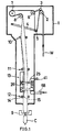
- FIG. 1 shows how to make pillow-shaped containers C filled with contents from a web W of packaging material having a polyethylene layer over each of its opposite surfaces.
- a seal tape S for preventing penetration of liquid is affixed to the inner surface of an inner edge portion of the web W (FIG. 2).
- an aseptic chamber 1 Arranged in the interior upper portion of an aseptic chamber 1 are a feed roller 2, holding roller 3, dance roller 5 mounted on the forward end of a pivotal arm 4 movable upward and downward, bending rollers 6, 7 and zigzag movement correcting roller 8.
- a feed roller 2 Arranged in the interior upper portion of an aseptic chamber 1 are a feed roller 2, holding roller 3, dance roller 5 mounted on the forward end of a pivotal arm 4 movable upward and downward, bending rollers 6, 7 and zigzag movement correcting roller 8.
- an upper forming roller ring 10 Arranged below the correcting roller 8 are an upper forming roller ring 10, intermediate forming roller ring 11 and lower forming roller ring 12.
- a seal roller 15 is disposed and provided as pressed against one roller 14 of the lower forming roller ring 12.
- the web W is transported downward from above successively through the upper and intermediate forming roller rings 10, 11, a heating device 13 and the lower forming roller ring 12. While the web W is being thus transported, the web W is formed generally into a tubular shape by the intermediate forming roller ring 11, with the inner surface of outer edge of the web W opposed to the outer surface of inner edge thereof and spaced apart therefrom by a predetermined distance, hot air is applied to the inner surface of outer edge of the web W by the heating device 13, and the inner surface of the outer edge of the web W and the outer surface of the inner edge thereof are heat-sealed by the lower forming roller ring 12 and the seal roller 15 to provide a lap.
- the web W formed into a tube is filled with contents by an unillustrated filling pipe and delivered from the aseptic chamber 1.
- the tubular web W filled with the contents and delivered from the chamber 1 is transported by a length corresponding to one container at a time, and sealed and out transversely thereof by a container forming device 9 (seal jaws only shown) disposed below the aseptic chamber 1 every time the web is so transported.
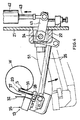
- the heating device 13 comprises a vertical rotatable shaft 24 supported by upper and lower bearings 22, 23 on the left side surface of a vertical support plate 21 disposed to the right of the path of transport of the web; a horizontal swing arm 25 fixed to an intermediate portion of the length of the shaft 24 and extending from the shaft 24 toward a position in front of the transport path; a hot air chamber 26 having a rectangular horizontal section and in the form of a vertically elongated box, the chamber 26 being attached to the forward end of the swing arm 25, positioned in front of the transport path obliquely leftward therefrom and extending along the path over a required distance; a nozzle 27 generally U-shaped in horizontal section and extending from the right end of rear side wall of the hot air chamber 26 obliquely rightwardly rearward; a heat-insulating plate 29 in the form of a vertical strip and attached to the right end of front side wall of the hot air chamber 26 by a connecting bar 28, the plate 29 being opposed to the right side wall of the chamber 26 and the nozzle 27 and space
- a rightwardly projecting operating am 41 Fixed to the upper end of the rotatable shaft 24 is a rightwardly projecting operating am 41, which has a right end connected to the piston rod 43 of a fluid pressure cylinder 42.
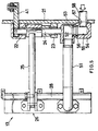
- a hot air communication pipe 51 extending toward the hot air chamber 26 has a right end secured to the lower end of the shaft 24.
- the right end of the pipe 51 is formed with a circular communication hole 52 concentric with the shaft 24.
- a slip ring 53 has an upper portion fitted in the communication hole 52 and rests on a joint 54.
- the joint 54 is formed with a hot air channel 55, which has an upward outlet 56 fittingly receiving the lower end of the slip ring 53 and a rightward inlet 57.
- a hot air supply pipe 58 is connected to the inlet 57.
- the hot air chamber 26 comprises a box-shaped body 61 opened rightward and having a large depth, a boxlike cover 62 having a left open side and a small depth, and a flow control plate 63 interposed between the chamber body 61 and the cover 62.
- the front side wall of the chamber body 61 is formed with an inlet 65 having the left end of the hot air communication pipe 51 connected thereto.
- the cover 62 has a rear side wall formed with an outlet 66 in communication with an open end of the nozzle 27.
- the nozzle 27 is integral with an edge portion of the cover rear side wall defining the outlet 66.
- the nozzle 27 has a left side wall formed with a multiplicity of distributed outlet openings 67.
- the heat-insulating plate 29 has a length approximately equal to that of the hot air chamber 26.
- the middle and lower rollers 31 are fitted respectively in two cutouts 71 formed in the plate 29.
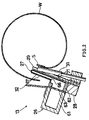
- the baffle plate 32 is approximately equal to the heat-insulating plate 29 in length, and is inclined relative to the left side wall of the nozzle 27 so as to be positioned at a gradually increasing distance therefrom as its extends rearward. With reference to FIG. 3, the baffle plate 32 is formed with a cutout 72 opened rearward and positioned at an intermediate portion of its length. While being transported, the web W can be inspected through the cutout.
- FIG. 4 shows in solid lines the present device as positioned during the transport of the web W.
- the outer surface of inner edge of the web W is brought into contact with the guide rollers 31 and thereby guided.
- the outer edge of the web W is held out of contact with any portion or member.
- the web W is pulled upward by the dancer roller 5 while being held between the seal jaws of the container forming device 9, whereby the web is tensioned as specified. Accordingly, the longitudinal edge portions of the web are unlikely to sway during transport, and the web W is held at a predetermined distance from each of the nozzle 27 and the babble plate 32 while traveling between the intermediate forming roller ring 11 and the lower forming roller ring 12.
- the hot air forced out from the nozzle 27 partly comes into contact with the inner surface of outer edge of the web W, whereby the polyethylene layer covering the surface is melted to a temperature suitable for heat sealing.
- the rest of the hot air advances straight as it is, and is deflected upon striking against the baffle plate 32.
- the hot air egressing from the nozzle 27 can be prevented from spreading out at a time although flowing inwardly and outwardly of the web W.
- the hot air is retained between the nozzle 27 and the baffle plate 32, and an atmosphere of high temperature is maintained in the vicinity of this region, heating the web W effectively.
- the fluid pressure cylinder 42 is operated to rotate the shaft 24 counterclockwise in FIG. 4, moving the swing arm 25 and the hot air communication pipe 51 and retracting the nozzle 27 to the position indicated in broken lines in FIG. 4.
- the nozzle 27 When the transport of the web W is to be resumed, the nozzle 27 is returned to the original position indicated in solid lines in FIG. 4. If the outer edge of the web W comes into contact with the nozzle 27 or the baffle plate 32 in this case, there is the likelihood that the polyethylene layer will be separated off from the outer edge of the web W, whereas the predetermined spacing provided between the web outer edge and each of the nozzle 27 and the baffle plate 32 obviates the likelihood.
- the cutout of the baffle plate in the device described above may be formed at more than one portion of the plate, or a hole may be formed instead of the cutout.
Landscapes
- Engineering & Computer Science (AREA)
- Mechanical Engineering (AREA)
- Health & Medical Sciences (AREA)
- Toxicology (AREA)
- Physics & Mathematics (AREA)
- Fluid Mechanics (AREA)
- Chemical & Material Sciences (AREA)
- Combustion & Propulsion (AREA)
- Containers And Plastic Fillers For Packaging (AREA)
- Package Closures (AREA)
- Making Paper Articles (AREA)
Applications Claiming Priority (3)
| Application Number | Priority Date | Filing Date | Title |
|---|---|---|---|
| JP16929196A JPH107110A (ja) | 1996-04-25 | 1996-06-28 | ウェッブ加熱装置 |
| JP169291/96 | 1996-06-28 | ||
| JP16929196 | 1996-06-28 |
Publications (2)
| Publication Number | Publication Date |
|---|---|
| EP0819607A1 true EP0819607A1 (fr) | 1998-01-21 |
| EP0819607B1 EP0819607B1 (fr) | 2000-01-26 |
Family
ID=15883802
Family Applications (1)
| Application Number | Title | Priority Date | Filing Date |
|---|---|---|---|
| EP19970201965 Expired - Lifetime EP0819607B1 (fr) | 1996-06-28 | 1997-06-27 | Dispositif pour chauffer une bande |
Country Status (4)
| Country | Link |
|---|---|
| US (1) | US5848517A (fr) |
| EP (1) | EP0819607B1 (fr) |
| DE (1) | DE69701207T2 (fr) |
| DK (1) | DK0819607T3 (fr) |
Cited By (12)
| Publication number | Priority date | Publication date | Assignee | Title |
|---|---|---|---|---|
| DE19804221A1 (de) * | 1998-02-04 | 1999-08-05 | Natec Reich Summer Gmbh Co Kg | Verfahren und Vorrichtung zur Herstellung eines kontinuierlichen Folienschlauchs aus einer ebenen Folienbahn |
| DE19809877A1 (de) * | 1998-03-07 | 1999-09-09 | Rovema Gmbh | Schlauchbeutelmaschine |
| WO2002016208A1 (fr) * | 2000-08-23 | 2002-02-28 | Molins Plc | Appareil de thermoscellage pour machine d'emballage |
| GB2374852B (en) * | 2001-03-28 | 2004-08-18 | Tna Australia Pty Ltd | Method and apparatus to aid in forming a package |
| WO2012066585A1 (fr) * | 2010-11-19 | 2012-05-24 | Minipack-Torre S.P.A. | Machine d'emballage automatique verticale et procédé de fonctionnement associé |
| EP2432697A4 (fr) * | 2009-05-19 | 2014-01-08 | Tetra Laval Holdings & Finance | Dispositif dans une machine de remplissage, machine de remplissage et procédé dans une machine de remplissage pour empêcher un mauvais collage des bords longitudinaux d'un matériau d'emballage |
| EP3620293A1 (fr) * | 2018-09-10 | 2020-03-11 | Tetra Laval Holdings & Finance S.A. | Procédé de formation d'un tube et procédé et machine d'emballage pour former un emballage |
| CN113700312A (zh) * | 2021-07-26 | 2021-11-26 | 安徽大禹防水科技发展有限公司 | 一种防水卷材搭接结构 |
| US11820540B2 (en) | 2018-09-11 | 2023-11-21 | Tetra Laval Holdings & Finance S.A. | Packaging apparatus for forming sealed packages |
| US12122547B2 (en) | 2019-02-05 | 2024-10-22 | Tetra Laval Holdings & Finance S.A. | Induction heat sealing device and a method for transversally seal a tube of packaging material |
| IT202400001107A1 (it) * | 2024-01-22 | 2025-07-22 | Tetra Laval Holdings & Finance | Apparato per l'applicazione di un nastro sigillante di materiale termosaldabile ad un nastro di materiale da incarto e macchina confezionatrice per formare pacchetti sigillati |
| US12522394B2 (en) | 2021-02-15 | 2026-01-13 | Tetra Laval Holdings & Finance S.A. | Method for assessing quality of a transversal sealing of a food package |
Families Citing this family (10)
| Publication number | Priority date | Publication date | Assignee | Title |
|---|---|---|---|---|
| JP4071321B2 (ja) * | 1997-08-13 | 2008-04-02 | 日本テトラパック株式会社 | 包材処理装置 |
| US6854245B1 (en) * | 1998-06-01 | 2005-02-15 | Burford Corp. | Tamper resistant closure |
| US6038839A (en) * | 1998-11-06 | 2000-03-21 | Triangle Package Machinery Company | Longitudinal seam sealer for polyethylene material |
| DE29822122U1 (de) * | 1998-12-11 | 2000-04-20 | Vision Verpackungstechnik GmbH, 35305 Grünberg | Einrichtung zum Bearbeiten von kontinuierlich durchlaufendem Material |
| DE10032551B4 (de) * | 2000-06-28 | 2004-06-03 | Drut, Henry, Dr.-Ing. | Formschulter und Vorrichtung zur Herstellung von längsgeformten Bahnen |
| JP2004149145A (ja) * | 2002-10-30 | 2004-05-27 | Nippon Seiki Co Ltd | 充填包装機 |
| SE528871C2 (sv) * | 2005-07-11 | 2007-03-06 | Tetra Laval Holdings & Finance | Anordning för uppvärmning av ett kantparti i ett ark för förpackningsmaterial |
| US9505191B2 (en) * | 2005-12-13 | 2016-11-29 | Delta Industrial Services, Inc. | Reciprocating sealer for web converters |
| JP7169997B2 (ja) | 2017-05-30 | 2022-11-11 | テトラ ラバル ホールディングス アンド ファイナンス エス エイ | 食品製品用パッケージの上部を密封するための装置及び食品パッケージを形成し充填するためのシステム |
| EP4644097A1 (fr) * | 2024-05-03 | 2025-11-05 | Tetra Laval Holdings & Finance S.A. | Dispositif pour diriger un flux d'air chauffé vers une bande de matériau d'emballage, unité de formage et de scellage pour former un tube à partir d'une bande de matériau d'emballage et machine d'emballage pour produire des emballages scellés à partir d'un matériau d'emballage |
Citations (2)
| Publication number | Priority date | Publication date | Assignee | Title |
|---|---|---|---|---|
| GB1195578A (en) * | 1966-09-28 | 1970-06-17 | Tetra Pak Ag | A method of producing a Tube from a Web and apparatus for performing the same |
| JPH0451138U (fr) * | 1990-09-04 | 1992-04-30 |
Family Cites Families (8)
| Publication number | Priority date | Publication date | Assignee | Title |
|---|---|---|---|---|
| US2899875A (en) * | 1959-08-18 | leasure | ||
| US3086336A (en) * | 1959-01-02 | 1963-04-23 | Hermorion Ltd | Apparatus for producing aseptic packages |
| US3562920A (en) * | 1969-02-17 | 1971-02-16 | Container Corp | Heat sealing device |
| CH540104A (de) * | 1971-07-09 | 1973-08-15 | Alpura Koreco Ag | Vorrichtung zum Verschweissen der Längskanten einer laufenden Bahn aus mit Kunststoff beschichtetem Verpackungsmaterial |
| US3925963A (en) * | 1973-04-04 | 1975-12-16 | Dow Chemical Co | Form, fill and seal industrial bag machine |
| US4103473A (en) * | 1977-08-24 | 1978-08-01 | Atlas Powder Company | Apparatus for making a compartmented container |
| JP3115302B2 (ja) * | 1990-06-19 | 2000-12-04 | 株式会社リコー | 原稿読み取り装置 |
| US5562795A (en) * | 1995-02-21 | 1996-10-08 | Kliklok Corporation | High speed carton feeding/heat sealing system |
-
1997
- 1997-06-27 US US08/884,140 patent/US5848517A/en not_active Expired - Fee Related
- 1997-06-27 DK DK97201965T patent/DK0819607T3/da active
- 1997-06-27 DE DE69701207T patent/DE69701207T2/de not_active Expired - Fee Related
- 1997-06-27 EP EP19970201965 patent/EP0819607B1/fr not_active Expired - Lifetime
Patent Citations (2)
| Publication number | Priority date | Publication date | Assignee | Title |
|---|---|---|---|---|
| GB1195578A (en) * | 1966-09-28 | 1970-06-17 | Tetra Pak Ag | A method of producing a Tube from a Web and apparatus for performing the same |
| JPH0451138U (fr) * | 1990-09-04 | 1992-04-30 |
Cited By (19)
| Publication number | Priority date | Publication date | Assignee | Title |
|---|---|---|---|---|
| DE19804221A1 (de) * | 1998-02-04 | 1999-08-05 | Natec Reich Summer Gmbh Co Kg | Verfahren und Vorrichtung zur Herstellung eines kontinuierlichen Folienschlauchs aus einer ebenen Folienbahn |
| DE19809877A1 (de) * | 1998-03-07 | 1999-09-09 | Rovema Gmbh | Schlauchbeutelmaschine |
| WO2002016208A1 (fr) * | 2000-08-23 | 2002-02-28 | Molins Plc | Appareil de thermoscellage pour machine d'emballage |
| AU2001279961B2 (en) * | 2000-08-23 | 2005-10-20 | Molins Plc | Heat sealing apparatus for packaging machinery |
| GB2374852B (en) * | 2001-03-28 | 2004-08-18 | Tna Australia Pty Ltd | Method and apparatus to aid in forming a package |
| EP2432697A4 (fr) * | 2009-05-19 | 2014-01-08 | Tetra Laval Holdings & Finance | Dispositif dans une machine de remplissage, machine de remplissage et procédé dans une machine de remplissage pour empêcher un mauvais collage des bords longitudinaux d'un matériau d'emballage |
| RU2528440C2 (ru) * | 2009-05-19 | 2014-09-20 | Тетра Лаваль Холдингз Энд Файнэнс С.А. | Устройство в расфасовочной машине, расфасовочная машина и способ предотвращения некорректного прилипания продольных краев упаковочного материала |
| WO2012066585A1 (fr) * | 2010-11-19 | 2012-05-24 | Minipack-Torre S.P.A. | Machine d'emballage automatique verticale et procédé de fonctionnement associé |
| EP3620293A1 (fr) * | 2018-09-10 | 2020-03-11 | Tetra Laval Holdings & Finance S.A. | Procédé de formation d'un tube et procédé et machine d'emballage pour former un emballage |
| WO2020053049A1 (fr) * | 2018-09-10 | 2020-03-19 | Tetra Laval Holdings & Finance S.A. | Procédé de formation d'un tube et procédé et machine à emballer permettant de former un emballage |
| US11548238B2 (en) | 2018-09-10 | 2023-01-10 | Tetra Laval Holdings & Finance S.A. | Method for forming a tube and a method and a packaging machine for forming a package |
| US11820540B2 (en) | 2018-09-11 | 2023-11-21 | Tetra Laval Holdings & Finance S.A. | Packaging apparatus for forming sealed packages |
| US12122547B2 (en) | 2019-02-05 | 2024-10-22 | Tetra Laval Holdings & Finance S.A. | Induction heat sealing device and a method for transversally seal a tube of packaging material |
| US12240643B2 (en) | 2019-02-05 | 2025-03-04 | Tetra Laval Holdings & Finance S.A. | Induction heat sealing device and a method for transversally seal a tube of packaging material |
| US12522394B2 (en) | 2021-02-15 | 2026-01-13 | Tetra Laval Holdings & Finance S.A. | Method for assessing quality of a transversal sealing of a food package |
| CN113700312A (zh) * | 2021-07-26 | 2021-11-26 | 安徽大禹防水科技发展有限公司 | 一种防水卷材搭接结构 |
| IT202400001107A1 (it) * | 2024-01-22 | 2025-07-22 | Tetra Laval Holdings & Finance | Apparato per l'applicazione di un nastro sigillante di materiale termosaldabile ad un nastro di materiale da incarto e macchina confezionatrice per formare pacchetti sigillati |
| EP4588646A1 (fr) * | 2024-01-22 | 2025-07-23 | Tetra Laval Holdings & Finance S.A. | Dispositif pour appliquer une bande d'étanchéité d'un matériau thermoscellable sur une bande de matériau d'emballage et machine d'emballage pour former des emballages scellés |
| WO2025157637A1 (fr) * | 2024-01-22 | 2025-07-31 | Tetra Laval Holdings & Finance S.A. | Appareil pour appliquer une bande d'étanchéité d'un matériau thermoscellable sur une bande de matériau d'emballage et machine d'emballage pour former des emballages scellés |
Also Published As
| Publication number | Publication date |
|---|---|
| US5848517A (en) | 1998-12-15 |
| DE69701207T2 (de) | 2000-06-21 |
| EP0819607B1 (fr) | 2000-01-26 |
| DK0819607T3 (da) | 2000-05-15 |
| DE69701207D1 (de) | 2000-03-02 |
Similar Documents
| Publication | Publication Date | Title |
|---|---|---|
| US5848517A (en) | Web heating device | |
| US5282349A (en) | Sealing and packaging method and apparatus | |
| US8245485B2 (en) | Vertical-type bag packaging method and apparatus | |
| US4715166A (en) | Film packaging apparatus | |
| CA1318298C (fr) | Appareil de remplissage de sacs de plastique souples transportes sur bande continue et fournitures connexes | |
| JPS62251309A (ja) | 袋状パツケ−ジを製造する装置 | |
| JPS5924937B2 (ja) | 包装袋への補助部品付着装置 | |
| US6155030A (en) | Sealing apparatus applied to a vertical type forming, filling and closing machine for flexible package | |
| US12110147B2 (en) | Horizontal forming device | |
| CN1483646A (zh) | 密封热密封过滤纸扁平管以制造浸泡产品过滤袋的设备 | |
| US20100115894A1 (en) | Bag-making and packaging machine | |
| EP0984887B1 (fr) | Dispositif et procede destines a une machine a remplir des tubes souples | |
| JPH107110A (ja) | ウェッブ加熱装置 | |
| US4524559A (en) | Hand wrapping apparatus | |
| EP3825240B1 (fr) | Machine à emballer pour produire des emballages refermables | |
| JPH02258509A (ja) | 充填包装機に於る包装袋閉じ合せ縁の余剰部切落装置 | |
| JP2017081573A (ja) | フォーマおよび縦形製袋機 | |
| JPH0429838A (ja) | 封筒製袋機 | |
| JPH0551853U (ja) | 包装機等におけるフィルム接合装置 | |
| JPH11170405A (ja) | 注出口付き包装体の製造方法及び製造装置 | |
| JP3719626B2 (ja) | 自動袋詰め装置 | |
| JPH0339231Y2 (fr) | ||
| KR100360582B1 (ko) | 포장기의 백성형장치와 그 방법 및 제품 | |
| JPH08183509A (ja) | 印刷物等の自動連続包装装置 | |
| KR950001145Y1 (ko) | 한방용 약액 포장장치 |
Legal Events
| Date | Code | Title | Description |
|---|---|---|---|
| PUAI | Public reference made under article 153(3) epc to a published international application that has entered the european phase |
Free format text: ORIGINAL CODE: 0009012 |
|
| AK | Designated contracting states |
Kind code of ref document: A1 Designated state(s): CH DE DK FR GB LI NL SE |
|
| 17P | Request for examination filed |
Effective date: 19980618 |
|
| AKX | Designation fees paid |
Free format text: CH DE DK FR GB LI NL SE |
|
| RBV | Designated contracting states (corrected) |
Designated state(s): CH DE DK FR GB LI NL SE |
|
| 17Q | First examination report despatched |
Effective date: 19981006 |
|
| GRAG | Despatch of communication of intention to grant |
Free format text: ORIGINAL CODE: EPIDOS AGRA |
|
| GRAG | Despatch of communication of intention to grant |
Free format text: ORIGINAL CODE: EPIDOS AGRA |
|
| GRAH | Despatch of communication of intention to grant a patent |
Free format text: ORIGINAL CODE: EPIDOS IGRA |
|
| GRAH | Despatch of communication of intention to grant a patent |
Free format text: ORIGINAL CODE: EPIDOS IGRA |
|
| GRAA | (expected) grant |
Free format text: ORIGINAL CODE: 0009210 |
|
| AK | Designated contracting states |
Kind code of ref document: B1 Designated state(s): CH DE DK FR GB LI NL SE |
|
| REG | Reference to a national code |
Ref country code: CH Ref legal event code: NV Representative=s name: PATENTANWALTSBUERO JEAN HUNZIKER Ref country code: CH Ref legal event code: EP |
|
| REF | Corresponds to: |
Ref document number: 69701207 Country of ref document: DE Date of ref document: 20000302 |
|
| REG | Reference to a national code |
Ref country code: DK Ref legal event code: T3 |
|
| ET | Fr: translation filed | ||
| PLBE | No opposition filed within time limit |
Free format text: ORIGINAL CODE: 0009261 |
|
| STAA | Information on the status of an ep patent application or granted ep patent |
Free format text: STATUS: NO OPPOSITION FILED WITHIN TIME LIMIT |
|
| 26N | No opposition filed | ||
| REG | Reference to a national code |
Ref country code: GB Ref legal event code: IF02 |
|
| PGFP | Annual fee paid to national office [announced via postgrant information from national office to epo] |
Ref country code: DE Payment date: 20020423 Year of fee payment: 6 |
|
| PGFP | Annual fee paid to national office [announced via postgrant information from national office to epo] |
Ref country code: SE Payment date: 20020617 Year of fee payment: 6 |
|
| PGFP | Annual fee paid to national office [announced via postgrant information from national office to epo] |
Ref country code: GB Payment date: 20020618 Year of fee payment: 6 |
|
| PGFP | Annual fee paid to national office [announced via postgrant information from national office to epo] |
Ref country code: DK Payment date: 20020625 Year of fee payment: 6 |
|
| PGFP | Annual fee paid to national office [announced via postgrant information from national office to epo] |
Ref country code: FR Payment date: 20020626 Year of fee payment: 6 |
|
| PGFP | Annual fee paid to national office [announced via postgrant information from national office to epo] |
Ref country code: NL Payment date: 20020628 Year of fee payment: 6 |
|
| PGFP | Annual fee paid to national office [announced via postgrant information from national office to epo] |
Ref country code: CH Payment date: 20020708 Year of fee payment: 6 |
|
| PG25 | Lapsed in a contracting state [announced via postgrant information from national office to epo] |
Ref country code: GB Free format text: LAPSE BECAUSE OF NON-PAYMENT OF DUE FEES Effective date: 20030627 |
|
| PG25 | Lapsed in a contracting state [announced via postgrant information from national office to epo] |
Ref country code: SE Free format text: LAPSE BECAUSE OF NON-PAYMENT OF DUE FEES Effective date: 20030628 |
|
| PG25 | Lapsed in a contracting state [announced via postgrant information from national office to epo] |
Ref country code: LI Free format text: LAPSE BECAUSE OF NON-PAYMENT OF DUE FEES Effective date: 20030630 Ref country code: DK Free format text: LAPSE BECAUSE OF NON-PAYMENT OF DUE FEES Effective date: 20030630 Ref country code: CH Free format text: LAPSE BECAUSE OF NON-PAYMENT OF DUE FEES Effective date: 20030630 |
|
| PG25 | Lapsed in a contracting state [announced via postgrant information from national office to epo] |
Ref country code: NL Free format text: LAPSE BECAUSE OF NON-PAYMENT OF DUE FEES Effective date: 20040101 Ref country code: DE Free format text: LAPSE BECAUSE OF NON-PAYMENT OF DUE FEES Effective date: 20040101 |
|
| REG | Reference to a national code |
Ref country code: DK Ref legal event code: EBP |
|
| EUG | Se: european patent has lapsed | ||
| REG | Reference to a national code |
Ref country code: CH Ref legal event code: PL |
|
| GBPC | Gb: european patent ceased through non-payment of renewal fee |
Effective date: 20030627 |
|
| PG25 | Lapsed in a contracting state [announced via postgrant information from national office to epo] |
Ref country code: FR Free format text: LAPSE BECAUSE OF NON-PAYMENT OF DUE FEES Effective date: 20040227 |
|
| NLV4 | Nl: lapsed or anulled due to non-payment of the annual fee |
Effective date: 20040101 |
|
| REG | Reference to a national code |
Ref country code: FR Ref legal event code: ST |