EP0819972A1 - Caméra numérique - Google Patents
Caméra numérique Download PDFInfo
- Publication number
- EP0819972A1 EP0819972A1 EP97112279A EP97112279A EP0819972A1 EP 0819972 A1 EP0819972 A1 EP 0819972A1 EP 97112279 A EP97112279 A EP 97112279A EP 97112279 A EP97112279 A EP 97112279A EP 0819972 A1 EP0819972 A1 EP 0819972A1
- Authority
- EP
- European Patent Office
- Prior art keywords
- emission
- light
- evaluation value
- weighting
- period
- Prior art date
- Legal status (The legal status is an assumption and is not a legal conclusion. Google has not performed a legal analysis and makes no representation as to the accuracy of the status listed.)
- Granted
Links
- 238000011156 evaluation Methods 0.000 claims abstract description 116
- 230000004044 response Effects 0.000 claims description 19
- 238000012545 processing Methods 0.000 claims description 13
- 238000001514 detection method Methods 0.000 claims description 4
- 230000010354 integration Effects 0.000 claims description 3
- 238000012546 transfer Methods 0.000 description 12
- 238000000034 method Methods 0.000 description 10
- 238000009825 accumulation Methods 0.000 description 7
- 238000010408 sweeping Methods 0.000 description 5
- 230000006870 function Effects 0.000 description 4
- 238000006243 chemical reaction Methods 0.000 description 3
- 230000003287 optical effect Effects 0.000 description 3
- 238000012937 correction Methods 0.000 description 2
- 230000000994 depressogenic effect Effects 0.000 description 2
- 238000010586 diagram Methods 0.000 description 2
- 238000005286 illumination Methods 0.000 description 2
- 238000005375 photometry Methods 0.000 description 2
- 239000013589 supplement Substances 0.000 description 2
- 241000208011 Digitalis Species 0.000 description 1
- 239000003086 colorant Substances 0.000 description 1
- 230000006835 compression Effects 0.000 description 1
- 238000007906 compression Methods 0.000 description 1
- 238000005516 engineering process Methods 0.000 description 1
- 238000000926 separation method Methods 0.000 description 1
Images


Classifications
-
- G—PHYSICS
- G03—PHOTOGRAPHY; CINEMATOGRAPHY; ANALOGOUS TECHNIQUES USING WAVES OTHER THAN OPTICAL WAVES; ELECTROGRAPHY; HOLOGRAPHY
- G03B—APPARATUS OR ARRANGEMENTS FOR TAKING PHOTOGRAPHS OR FOR PROJECTING OR VIEWING THEM; APPARATUS OR ARRANGEMENTS EMPLOYING ANALOGOUS TECHNIQUES USING WAVES OTHER THAN OPTICAL WAVES; ACCESSORIES THEREFOR
- G03B7/00—Control of exposure by setting shutters, diaphragms or filters, separately or conjointly
- G03B7/16—Control of exposure by setting shutters, diaphragms or filters, separately or conjointly in accordance with both the intensity of the flash source and the distance of the flash source from the object, e.g. in accordance with the "guide number" of the flash bulb and the focusing of the camera
-
- H—ELECTRICITY
- H04—ELECTRIC COMMUNICATION TECHNIQUE
- H04N—PICTORIAL COMMUNICATION, e.g. TELEVISION
- H04N23/00—Cameras or camera modules comprising electronic image sensors; Control thereof
- H04N23/70—Circuitry for compensating brightness variation in the scene
- H04N23/73—Circuitry for compensating brightness variation in the scene by influencing the exposure time
-
- H—ELECTRICITY
- H04—ELECTRIC COMMUNICATION TECHNIQUE
- H04N—PICTORIAL COMMUNICATION, e.g. TELEVISION
- H04N23/00—Cameras or camera modules comprising electronic image sensors; Control thereof
- H04N23/70—Circuitry for compensating brightness variation in the scene
- H04N23/74—Circuitry for compensating brightness variation in the scene by influencing the scene brightness using illuminating means
Definitions
- the present invention relates to a digital camera. More specifically, the present invention relates to a digital camera for taking a picture of an object by making a flash lamp perform a light-emission with a major light-emission amount and by exposing a picture taking means for a first period.
- a luminance level of the object is calculated by making a flash lamp perform a preliminary light-emission, and the major light-emission amount of the flash lamp is calculated on the basis of the luminance level.
- a luminance level Es is detected by making the flash lamp perform the preliminary light-emission, the major light-emission amount is calculated on the basis of a luminance level Es, and the flash lamp is light-emitted with the major light-emission amount, therefore, a shortage amount of the luminance level is supplemented.
- the principal object of the present invention is to provide a novel digital camera.
- Another object of the present invention is to provide a digital camera capable of precisely calculating a major light-emission element of a flash lamp.
- Further object of the present invention is to provide a digital camera capable of calculating a most suitable major light-emission element in a set mode.
- a digital camera for taking a picture of an object by making a flash lamp perform a major light-emission with a major light-emission amount and exposing a picture taking means for a first period comprises: a detection means for detecting a luminance signal from a camera signal outputted from the picture taking means; an evaluation means for evaluating the luminance signal and outputting a luminance evaluation value; a first control means for exposing the picture taking means without a light-emission of the flash lamp; a second control means for making the flash lamp perform a preliminary light-emission with a preliminary light-emission amount and exposing the picture taking means for a second period shorter than the first period; and a calculation means for calculating the major light-emission amount on the basis of a first non-emission luminance evaluation value outputted from the evaluation means in response to a control of the first control means and a preliminary light-emission luminance evaluation value outputted from the evaluation means in response to a control of the second control means.
- the first control means exposes the picture taking means without the light-emission of the flash lamp, therefore, the first non-emission luminance evaluation value is obtained from the evaluation means.
- the second control means makes the flash lamp perform the preliminary light-emission with the preliminary light-emission amount, and exposes the picture taking means for the second period, therefore, the preliminary light-emission luminance evaluation value is obtained from the evaluation means.
- the calculation means calculates the major light-emission amount on the basis of the first non-emission luminance evaluation value and the preliminary light-emission luminance evaluation value.
- the flash lamp is light-emitted with the major light-emission amount, and the picture taking means is exposed for the first period at this time.
- the second period is defined to be shorter than the first period.
- the first control means exposes the picture taking means for a third period.
- a luminance evaluation value calculation means calculates a second non-emission luminance evaluation value in exposing the picture taking means for the first period without the light-emission of the flash lamp, on the basis of the first period, the third period and the first non-emission luminance evaluation value.
- a major light-emission amount calculation means calculates the major light-emission amount on the basis of the second non-emission luminance evaluation value, a target luminance evaluation value, the preliminary light-emission luminance evaluation value and the preliminary light-emission amount.
- an exposure period calculation means calculates a most suitable exposure period in which the target luminance evaluation value is obtained without the light-emission of the flash lamp, on the basis of the third period, the first non-emission luminance evaluation value and the target luminance evaluation value. If the most suitable exposure period is shorter than a longest exposure period which is a longest period capable of exposing the picture taking means, a cancellation means cancels the major light-emission. That is, since the target luminance evaluation value is obtained without the major light-emission, the cancellation means cancels the major light-emission.
- the preliminary light-emission luminance evaluation value is not influenced by an external light, therefore, it is possible to precisely calculate the major light-emission amount.
- a digital camera for taking a picture of an object by making a flash lamp perform a major light-emission with a major light-emission amount and by exposing a picture taking means comprises: a mode setting means for setting one of a first mode and a second mode; a first weighting amount table in which first weighting amount data is stored; a second weighting amount table in which second weighting amount data is stored; a detection means for detecting a luminance signal from a camera signal outputted from the picture taking means; a weighting means for weighting the luminance signal with a table corresponding to a set mode; a calculation means for calculating an output of the weighting means and outputting a luminance evaluation value; a first control means for making the flash lamp perform a preliminary light-emission and exposing the picture taking means; and a first computing means for computing the major light-emission amount on the basis of a preliminary light-emission luminance evaluation value outputted from the calculation means in response to an operation of the first control means.
- the first control means makes the flash lamp perform the preliminary light-emission and exposes the picture taking means, whereby the camera signal is outputted from the picture taking means.
- the weighting means weights the luminance signal included in the camera signal with the first weighting amount table.
- the weighting means weights the luminance signal included in the camera signal with the second weighting amount table.
- the output of the weighting means is calculated by the calculation means, and the fist computing means computes the major light-emission amount on the basis of the preliminary light-emission luminance evaluation value outputted from the calculation means.
- the second control means exposes the picture taking means without the light-emission of the flash lamp, and the weighting means selects the first weighting amount table at this time. Then, a second computing means computes a most suitable exposure period in which a target luminance evaluation value is obtained without the light-emission of the flash lamp, on the basis of a second luminance evaluation value outputted from the calculation means in response to an operation of a second control means.
- the most suitable exposure period is compared with a longest exposure period which is a longest period capable of exposing the picture taking means, if the most suitable exposure period is shorter than the longest exposure period, the major light-emission is cancelled.
- the first mode is an automatic light-emission mode in which the major light-emission is performed in response to the most suitable exposure period, and the first weighting amount data in a surrounding portion of the object is smaller than the first weighting amount data in a center portion of the object and larger than "0".
- the most suitable exposure period and the longest exposure period are compared with each other, if the most suitable exposure period is shorter than the longest exposure period, the most suitable exposure period is held as an exposure period in the major light-emission, and if the most suitable exposure period is equal to the longest exposure period or longer than the longest exposure period, the longest exposure period is held as the exposure period in the major light-emission.
- the second mode is a forced light-emission mode for making the flash lamp perform the major light-emission without respect to the most suitable exposure period, and the second weighting amount data has a value of "0" in the surrounding portion of the object.
- the table is changed in response to the set mode, it is possible to calculate the most suitable major light-emission amount for the mode.
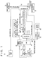
- Figure 1 is a block diagram showing a digital camera 10 of this embodiment.
- a reference numeral "12" denotes a CCD imager for subjecting an optical image applied through an optical system to a photoelectric conversion and outputting a camera signal.
- a plurality of light receiving portions 12 are formed on the CCD imager 12 as shown in Figure 2, a color filter 13 in which the three primary colors of R, G and B are arranged in mosaic like as shown in Figure 3 is attached in front of the light receiving portions 12a.
- the light receiving portions 12a constitutes respective pixels of the CCD imager 12, and one of R, G and B arranged in the color filter 13 corresponds to one light receiving portion 12a.
- the optical image passed through a lens is applied to the light receiving portions 12a of the CCD imager 12 through the color filter 13 and subjected to the photoelectric conversion. Charges obtained in such a manner are accumulated in an exposure period, that is a charge accumulation period, determined in response to a shutter speed, thereafter, the charges are outputted.
- the CCD imager 12 includes the plurality of light receiving portions 12a each of which corresponds to one pixel, a plurality of vertical transfer registers 12b for transferring in the vertical direction the charges obtained by the photoelectric conversion and accumulated in such light receiving portions 12a and a vertical transfer register 12c provided at ends of the respective vertical transfer registers 12b and for transferring in the horizontal direction the charges transferred by the vertical transfer registers 12b, and the CCD imager 12 is driven by timing signals outputted from a timing generator 18.
- a reading pulse for reading out the charges from the light receiving portions 12a to apply the charges to the vertical transfer registers 12b there are a reading pulse for reading out the charges from the light receiving portions 12a to apply the charges to the vertical transfer registers 12b, a vertical transfer pulse for transferring the charges in the vertical transfer registers 12b for each line in the vertical direction, a horizontal transfer pulse for transferring the charges in the horizontal transfer register 12c for each pixel in the horizontal direction, a sweeping pulse for sweeping the charges generated by the light receiving portions 12a in a non-exposure period, that is, non-charge accumulation period, and etc.
- the timing generator 18 controls a period for outputting the sweeping pulse in response to a shutter speed instruction signal described below. Therefore, the charge accumulation period is controlled, and a desired shutter speed is obtained.
- a technology for controlling the shutter speed in response to an output period of the sweeping pulse in such a manner is well-known as an electronic shutter function.
- the charges are generated by the CCD imager 12 for the respective pixels, and successively outputted as an image signal.
- the color filter 13 is formed as shown in Figure 3, when accumulation of the charges is completed in the CCD imager 12, a G signal passed through a filter element of green existing at a lower left end is first outputted, succeedingly, a B signal passed through the filter element of blue adjacent to the filter element of green at the right side is outputted.
- a G signal passed through a filter element of green existing at a lower left end is first outputted, succeedingly, a B signal passed through the filter element of blue adjacent to the filter element of green at the right side is outputted.
- a reference numeral "14" denotes an A/D converter for successively digitalis the image signal outputted from the CCD imager 12, that is the color signals corresponding to the respective filter elements, and an output of the A/D converter 14 is sequentially written to a RAM 16 as image data.
- Writing to the RAM 16 is controlled by a writing control signal from a memory control circuit 40.
- a plurality of addresses corresponding to the respective pixels of the CCD imager 12 are previously applied to the RAM 16.
- the memory control circuit 40 controls the writing on the basis of the timing signals from the timing generator 18 such that each color data included in the image data is memorized in a desired address.
- which pixel of the CCD imager 12 the inputted color data corresponds to is determined by a count value of a vertical counter which is reset by the reading pulse and incremented by the vertical transfer pulse, and a count value of a horizontal counter which is reset by the vertical transfer pulse and incremented by the horizontal transfer pulse.
- the charges of all the pixels are fetched out at every time the CCD imager 12 is exposed, and the image data in which each pixel has one color component of R, G and B is to be memorized into the RAM 16.
- one block is defined by three pixels including the filter elements of R, G and B one by one like a character "L" in the color filter 13, and a plurality of blocks Bm, n (m, n :integer) such as B 1,1 , B 1,2 ⁇ are formed.
- the color data of R, G or B is read out at every block in accordance with a reading control signal from the memory control circuit 40.
- underlines are applied to the filter element forming each block, and the each block is surrounded by a slid line.
- the filter elements of R, G and B included in each block are divided by dotted lines.
- a reference numeral "20" denotes a calculator for generating luminance data Dy showing a level of a luminance signal Y, color difference data Dr showing a level of a color difference signal R - Y and color difference data Db showing a level of a color difference signal B - Y by substituting the color data of R, G and B included in the same block and read out into a predetermined equation. If the respective color data of R, G and B in a black are defined by "r”, “g” and "b”, the equation is shown as below.
- the luminance data Dy calculated in such a manner is inputted to a weighting circuit 22.
- the weighting circuit 22 subjects a weighting operation to the luminance data Dy in accordance with weighting amount data K held in a first weighting amount table 28 or a second weighting amount table 30. That is, the weighting circuit 22 multiplies the luminance data Dy by the weighting amount data K.
- the first weighting amount table 28 and the second weighting amount table 30 receive reading address data from the memory control circuit 40, and recognize which block of R, G and B data the luminance data and the color difference data outputted from the calculator 20 are generated from. Then, the first weighting amount table 28 and the second weighting amount table 30 output the weighting amount data K corresponding to a noted block.
- the first weighting amount table 28 is divided into 256 areas Ai, j (i, j : integers from 1 to 16) having 16 areas in the vertical direction and 16 areas in the horizontal direction as shown in Figure 5, and the weighting amount data K having a value of "1", "2" or "3" is corresponded to each area.
- Each area Ai, j is larger than each block Bi, j, and a plurality of blocks Bm, n included in one area Ai, j have the same weighting amount data K.
- the first weighting amount table 28 detects an area relating to the luminance data and the color difference data outputted from the calculator 20, and applies the weighting amount data K corresponding to the detected area to the weighting circuit 22.
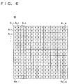
- the second weighting amount table 30 is also divided into 256 areas Ai, j (i, j : integers from 1 to 16) having 16 areas in the vertical direction and 16 areas in the horizontal direction as shown in Figure 6, and the weighting amount data K having a value of "0", “1", “2", “4" or "6" is corresponded to each area.
- the second weighting amount table 30 detects an area relating to the luminance data and the color difference data outputted from the calculator 20, and applies the weighting amount data K corresponding to the detected area to the weighting circuit 22.
- the weighting amount data K has a value of "3" in 16 areas of the center, the weighting amount data K has a value of "2" in 36 areas which is surround the 16 areas and in which a possibility of existence of the main object is a little low, and the weighting amount data K has a value of "1" in the remained areas of the outside in which the possibility is drastically low.
- the weighting amount data K has a drastically large value "6" in 4 areas of the center in which there is a high possibility of the existence of the main object, and the weighting amount data K has a value "4" a little smaller than "6" in 8 areas which surrounds the 4 areas and that the possibility of the existence of the main object is a little low. Furthermore, the weighting amount data K has a value "2" a little smaller than "4" in 20 areas which surrounds such 8 areas and that the possibility is a little low, and the weighting amount data K has a value "1" a little smaller than "2" in 20 areas which surrounds such 20 areas and that the possibility is a little low.
- a value "0" is applied to the remained area.
- the value "0" means that the luminance level in the remained areas is substantially excluded in calculating an evaluation value described later.
- a reference symbol SW2 denotes a switch for selecting one of the weighting amount data outputted from the first weighting amount table 28 and the second weighting amount table 30 to apply to the weighting circuit 22, and the switch SW2 is controlled by a second switching signal from a microcomputer 32 described later.
- a reference numeral 24 denotes an integrator for calculating a total sum of the luminance data equal to one screen to which the weighting operation is performed in the weighting circuit 22, that is, for digitally integrating the luminance data through one screen.
- Each of the first weighting amount table 28 and the second weighting amount table 30 has 256 weighting amount data in response to the respective luminance data Dy.
- the calculator 26 normalizes an integrated value from the integrator 24 by dividing the integrated value with a total sum of the 256 weighting amount data so as to calculate a luminance evaluation value Vy being an evaluation object in an exposure adjustment.
- the two color difference data simultaneously outputted from the calculator 20 with the luminance data are used for a white balance adjustment operation in a white balance adjustment circuit not shown.
- the microcomputer 32 determines the exposure period of the CCD imager 12, that is the shutter speed, for the exposure adjustment on the basis of the luminance evaluation value Vy applied from the calculator 26.
- the microcomputer 32 also instructs a timing of the exposure of the CCD imager 12, that is a timing of picture taking, on the basis of the determined shutter speed.
- the microcomputer 32 controls a light-emission of the flash lamp 38 and switching of the switches SW1 and SW2 on the basis of a shutter release instruction from a shutter release button 36 and the luminance evaluation value Vy.
- the flash lamp 38 emits a light by a period instructed by a flash instruction from the microcomputer 32.
- a light-emission period of the flash lamp 38 determines a light-emission amount, the longer the light-emission period is, the larger the light-emission amount is.
- the shutter release button 36 inputs the shutter release instruction to the microcomputer 32 in response to a depression of an operator.
- a signal processing circuit 42 receives the image data memorized in the RAM 16 through the switch SW1 after the shutter release instruction is inputted, and subjects a well-known signal processing such as a color separation, a gamma correction, signal compression and etc. to the image data, and output still image data.
- the still image data is recorded into a record medium 44 such as a flash memory and a memory card, for example, by the microcomputer 32.
- the switch SW1 is controlled by a first switching signal outputted from the microcomputer 32.
- a reference numeral 34 denotes a mode selecting button 34 for selecting one of an automatic light-emission mode and a forced light-emission mode in response to an operation of the operator, and a mode setting signal for setting a selected mode is inputted to the microcomputer 32.
- the microcomputer 32 controls the switch SW2 by the second switching signal in response to the mode setting signal. More specifically, in a case where the automatic light-emission mode is selected by the mode selecting button 34, the switch SW2 is connected to a side of the first weighting amount table 28.
- the switch SW2 is connected to the side of the first weighting amount table 30 in the exposure adjustment, and the switch SW2 is connected to a side of the second weighting amount table 30 in calculating the light-emission amount of the flash lamp 38.
- the automatic light-emission mode means a mode for making the flash lamp 38 perform a major light-emission to supplement a shortage amount in only a case where an exposure shortage cannot be dissolved even if the shutter speed is set into a minimum speed by the exposure adjustment operation, and it is desirable to select the automatic light-emission mode in a normal picture taking state.
- the forced light-emission mode means a mode for back light correction in which the flash lamp 38 always emits the light to optimize a light amount of the main object in a case where the main object in the center of the screen becomes a back light state by the drastically high luminance behind the main object.
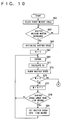
- FIG. 7 to 12 show flowcharts of the forced light-emission mode.
- the operation is executed in accordance with the flowcharts shown in Figure 7 to 9, and inversely, in a case where the forced light-emission mode is selected, the operation is executed in accordance with the flowcharts shown in Figure 10 to 12.
- the operation of the automatic light-emission mode is first described.
- the first weighting amount table is selected by the switch SW2 in a step S1
- the process proceeds to a step S3. If it is determined that the shutter release button 36 is depressed by the operator whereby the shutter release instruction is inputted to the microcomputer 32 in the step S3, the microcomputer 32 first starts the exposure adjustment operation. That is, the microcomputer 32 applies a shutter speed setting signal to the timing generator 18 so as to initialize the shutter speed into 1/250 second as a middle speed in a step S5.
- the timing generator 18 receives the shutter speed setting signal, and controls the output period of the sweeping pulse to the CCD imager 12 such that the charge accumulation period becomes 1/250 seconds.
- a variable N is initialized into "1" so as to repeat the exposure adjustment for 3 flames in a step S7, and a first exposure is performed at the shutter speed of 1/250 seconds in a step S9. Thereafter, the luminance evaluation value Vy is calculated in a step S11.
- the calculator 20 calculates the luminance data and the color difference data on the basis of the image data. Only the luminance data Dy is subjected to the weighting operation in the weighting circuit 22 in accordance with the weighting amount data K stored in the first weighting amount table 28, whereby the luminance data attached importance to the center of the screen is obtained.
- the integrator 24 digitally integrates the luminance data equal to 1 frame, and the accumulator 26 divides the integrated value by the total sum of the weighting amount data, whereby the luminance evaluation value Vy is calculated attaching importance to the center of the screen.
- the microcomputer 32 compares the luminance evaluation value Vy with a target evaluation value Yt to be obtained at a most suitable exposure state in a step S13, and renews the shutter speed such that the luminance evaluation value Vy is consistent with the target evaluation value Yt. More specifically, the microcomputer 32 multiplies a current shutter speed by Yt/Vy to obtain a renewed shutter speed for a succeeding exposure. If the luminance evaluation value is "50" and the target evaluation value is "100", for example, since the luminance level is only a half of a most suitable value, the shutter speed is renewed from the current 1/250 second to 1/125 second of a low speed.
- the microcomputer 32 determines whether or not the exposure for adjusting the shutter speed has been executed for three times in a step S15, if under three times, the microcomputer 32 increments the variable N in a step S17. Furthermore, the microcomputer 32 determines whether or not the shutter speed for the succeeding exposure renewed in the step S13 is lower speed than 1/30 second, that is, the exposure period is longer than 1/30 second in a step S19, if "YES", the microcomputer 32 sets the shutter speed into 1/30 second. Processes of the steps S19 and S21 are provided with considering that a minimum value of the shutter speed is 1/30 second, and the shutter speed cannot be actually set into a lower speed than the minimum value in the digital camera 10 of this embodiment. Accordingly, in a case where a shutter speed lower than the minimum value is calculated during the exposure adjustment operation, the shutter speed is forcedly set into the minimum value.
- the process is returned back to the step S9, a series of operation described above is repeated. That is, the shutter speed for a third exposure is obtained by a second exposure, and the shutter speed of a fourth exposure is obtained by the third exposure.
- the process proceeds from the step S15 to a step S23, and it is determined whether or not the light-emission of the flash lamp 38 is needed.
- the shutter speed for the fourth exposure which is finally obtained in a step S13 is lower than 1/30 second which is the lowest speed value of the shutter speed that the digital camera 10 of this embodiment permits, that is, whether or not the luminance evaluation value Vy does not reach the target evaluation value Yt if the charge accumulation period is not longer than 1/30 second in a first exposure after the exposure adjustment is completed.
- the shutter speed is 1/30 second or higher than 1/30 second, that is, it is determined that the exposure period is 1/30 second or shorter than 1/30 second, since the most suitable exposure is obtained at the shutter speed, it is determined that no light-emission of the flash lamp 38 is needed.
- the process proceeds to a step S25 to control the light-emission of the flash lamp 38.
- step S23 If it is determined that no light-emission of the flash lamp 38 is needed in the step S23, the process proceeds to a step S41, and the CCD imager 12 is exposed at the shutter speed renewed in the step S13 and the most suitable exposure state is obtained. That is, the microcomputer 32 cancels the light-emission of the flash lamp 38 and takes the picture of the object. Then, the image data obtained in a step S55 is recorded into the record medium 44 through the signal processing circuit 42 as the still image data.
- the image data due to the exposure in the step S41 can be inputted to the signal processing circuit 42 by outputting the first switching signal to open the switch SW1 at a timing that a predetermined period has passed from the exposure in the step S41.
- the shutter speed used in the third exposure is stored in a memory 32a included in the microcomputer 32 before the shutter speed for the fourth exposure is calculated in the step S13.
- 1/30 second is equal to a first period
- the shutter speed used in the third exposure is equal to the third period.
- the luminance evaluation value Vy obtained by the third exposure is equal to a first non-emission luminance evaluation value
- non-emission luminance evaluation value Y 0 is equal to a second non-emission luminance evaluation value.
- the non-emission luminance evaluation value Y 0 is calculated as the luminance evaluation value at the shutter speed of 1/30 second in such a manner
- a difference between the target evaluation value Yt and the non-emission luminance evaluation value Y 0 is calculated as the shortage amount U of the luminance in a step S29
- the shutter speed setting signal is applied to the timing generator 18 so as to set the shutter speed into 1/1500 second in a step S31.
- the CCD imager 12 starts the exposure at the shutter speed of 1/1500 second in a step S33.
- the microcomputer 16 outputs the flash instruction for a preliminary light-emission to the flash lamp 38 at the same time as an output of the shutter speed setting signal. If the flash lamp 38 receives the flash instruction for the preliminary light-emission, the flash lamp 38 emits the light such as the light-emission amount becomes P during the exposure of the CCD imager 12. In addition, this light-emission state is called as the preliminary light-emission state that the light-emission is preliminarily performed before the major light-emission described later.
- the image data obtained is written into the RAM 16. Succeedingly, the weighting operation attaching importance to the center is performed in similar to the weighting operation in a non-emission state described above in a step S39, and the luminance evaluation value Vy in the preliminary light-emission is calculated by the calculator 26.
- the microcomputer 32 regards the luminance evaluation value Vy in the preliminary light-emission as a preliminary light-emission luminance evaluation value Ys in a step S43.
- the microcomputer 32 calculates a major light-emission amount Q of the flash lamp 38 in the major light-emission in accordance with a following equation in a step S45.
- Q (U/Ys) ⁇ P
- the microcomputer 32 thereafter outputs the shutter speed setting signal for setting the shutter speed into 1/30 second to the timing generator 18 in a step S47.
- the major light-emission amount Q of the flash lamp 38 is determined and the shutter speed is defined, and the CCD imager 12 starts a major exposure in a step S49.
- the microcomputer 32 outputs the flash instruction for the major light-emission to the flash lamp 38, and the flash lamp 38 emits the light during the exposure of the CCD imager 12 by a period equal to the major light-emission amount Q in a step S51.
- the microcomputer 32 outputs the first switching signal so as to close the switch SW1 which is keeping an open state until now at a time that a predetermined period has passed from the start of the exposure in the step S49.
- the switch SW1 becomes a close state in response to the first switching signal.
- the signal processing circuit 42 subjects the signal processing to the image data obtained due to the exposure in the step S55 and read out from the RAM 16, and the still image data processed by the signal processing circuit 42 is recorded into the record medium 44.
- the luminance of the surrounding area is considered in determining necessity of the light-emission of the flash lamp 38 and the major light-emission amount, therefore, an object included in the surrounding can receive a suitable light amount.
- the switch SW2 selects in a step S61 the first weighting amount table 28 for the exposure adjustment precedingly executed, and in the exposure adjustment in the forced light-emission mode, the luminance evaluation value is calculated with using the weighting amount data of the first weighting amount table 28.
- the exposure adjustment operation from a step S65 to a step S81 is executed for three times, and then the process proceeds to a step S83.
- the luminance data Dy obtained due to a third exposure in a step S69 is held in a memory (not shown) provided between the calculator 20 and the weighting circuit 22.
- the shutter speed obtained by a third process of a step S73 also stored in the same memory.
- step S83 it is determined whether or not the shutter speed finally obtained in a step S73 by a third exposure evaluation is lower speed than 1/30 second, if lower speed than 1/30 second, the shutter speed is forcedly set into 1/30 second in a step S85.
- the shutter speed for a major exposure is obtained in the step S73 or S85 in such a manner, since the shutter speed is changed for the preliminary light-emission succeedingly executed, the shutter speed for the major exposure once obtained is held in the memory 32a included in the microcomputer 32 so as to save the shutter speed in a step S87.
- the second switching signal connects the switch SW2 to the side of the second weighting amount table 30 in a step S89. Accordingly, in calculating the luminance evaluation value of the screen hereafter, the second weighting amount table 30 considering only the center of the screen is used.
- a step S91 the luminance evaluation value Vy is calculated from the luminance data Dy precedingly held in the memory and based on the third exposure, succeedingly, a non-emission luminance evaluation value Ya is calculated in accordance with a following equation.
- Non-emission luminance evaluation value Ya ⁇ (shutter speed in major light-emission) / (shutter speed of third time) ⁇ ⁇ luminance evaluation value Vy.
- the shutter speed calculated at a time that the first weighting amount table 28 is selected is reflected to the equation. That is, the non-emission luminance evaluation value Ya is calculated with considering to some extent a surrounding luminance. Accordingly, the non-emission uminance evaluation value Ya becomes large in this case in comparison with a case where the non-emission luminance evaluation value Ya is calculated on the basis of only the luminance of the center, therefore, saturation of the surrounding luminance is controlled in a back light state.
- the non-emission luminance evaluation value Ya and the target evaluation value Yt are compared with each other in a step S93.
- the major light-emission amount is determined in steps S97 to S111.
- the light-emission amount of the flash lamp 38 is in a step S95 set into a minimum light-emission amount Pmin previously defined, thereafter the process proceeds to a step S113.
- the major light-emission amount Q calculated in the step S111 on the basis of the luminance evaluation value Vy also becomes a light-emission amount considering only a center area.
- the shutter speed for the major light-emission saved in the previous step S87 is fetched from the memory 32a, and the shutter speed setting signal showing the fetched shutter speed is applied to the timing generator 18, and the major exposure is executed in a step S117 at the shutter speed.
- the flash lamp 38 emits the light with the major light-emission amount Q determined in the step S111 or the major light-emission amount Pmin determined in the step S95, and the image data obtained after the exposure has completed is recorded into the record midium 44 in a step S121.
- the major light-emission amount Pmin is set into the minimum value capable of a little increasing the luminance of the main object with considering the operator dare to select the forced light-emission mode, though the exposure shortage concerning to the main object is already dissolved by the exposure adjustment.
- the luminance of the screen is evaluated with using the first weighting amount table 28, therefore, the exposure adjustment is executed attaching importance to the main object in the center of the screen and considering the surrounding area. Accordingly, a suitable exposure is obtained concerning to the object in the surrounding area. Furthermore, in a case where the exposure shortage occurs even if the exposure adjustment is executed, the luminance of the screen is evaluated with considering only the center area with using the second weighting amount table 30. That is, a light source etc. being put in the surrounding area is excluded from an evaluation object, and the exposure shortage concerning to only the main object in the center area is supplemented. Therefore, it is possible to correct the back light.
- the shutter speed in the preliminary light-emission is made high such that the influence of the external light excepting a light of the flash lamp can be excluded in any mode, even if a light of illumination is included in the object, and the light of the illumination is changed by the flicker, it is possible to precisely determine the major light-emission amount Q without the influence of the flicker.
- the luminance evaluation value may be calculated with thinning out some blocks such as specific one block is to be an object for the digitally integration out of ten blocks in both the horizontal direction and the vertical direction so as to shorten a processing period.
- functions of the weighting amount table 28, the weighting circuit 22, the calculators 20 and 26, the integrator 24 and the signal processing circuit 42 may be put into a single microcomputer with a function of the microcomputer 32 so as to process such functions by a software.
- the shutter speed is not particularly restricted to 1/1500 second. That is, since a light-emission period of the flash lamp 38 in the preliminary light-emission is approximately 50 microseconds, the shutter speed has only to satisfy a condition that the shutter speed, that is, the exposure period is longer than the light-emission period, and to sufficiently restrain the influence of the external light, and even if the shutter speed is 1/2000 second, 1/5000 second and 1/10000 second as a maximum speed, a similar advantage is obtained. It is ideally desirable that the shutter speed, that is, the exposure period is extremely close to the light-emission period of the flash lamp 38.
- the shutter speed is set into 1/30 second in the main light-emission
- the shutter speed is not restricted to the speed, and the shutter speed may be set into 1/29 second etc., for example, so as to obtain a sufficient exposure.
- the shutter speed may be set into 1/50 second, for example, with considering an unintentional vibration.
Landscapes
- Engineering & Computer Science (AREA)
- Multimedia (AREA)
- Signal Processing (AREA)
- Physics & Mathematics (AREA)
- General Physics & Mathematics (AREA)
- Studio Devices (AREA)
- Stroboscope Apparatuses (AREA)
Applications Claiming Priority (6)
| Application Number | Priority Date | Filing Date | Title |
|---|---|---|---|
| JP18962296A JP3384691B2 (ja) | 1996-07-18 | 1996-07-18 | 電子スチルカメラ |
| JP8189621A JPH1032750A (ja) | 1996-07-18 | 1996-07-18 | 電子スチルカメラ |
| JP18962196 | 1996-07-18 | ||
| JP18962296 | 1996-07-18 | ||
| JP189621/96 | 1996-07-18 | ||
| JP189622/96 | 1996-07-18 |
Publications (2)
| Publication Number | Publication Date |
|---|---|
| EP0819972A1 true EP0819972A1 (fr) | 1998-01-21 |
| EP0819972B1 EP0819972B1 (fr) | 2004-09-29 |
Family
ID=26505572
Family Applications (1)
| Application Number | Title | Priority Date | Filing Date |
|---|---|---|---|
| EP97112279A Expired - Lifetime EP0819972B1 (fr) | 1996-07-18 | 1997-07-17 | Caméra numérique |
Country Status (4)
| Country | Link |
|---|---|
| US (2) | US6195127B1 (fr) |
| EP (1) | EP0819972B1 (fr) |
| CN (1) | CN1135429C (fr) |
| DE (1) | DE69730915T2 (fr) |
Families Citing this family (68)
| Publication number | Priority date | Publication date | Assignee | Title |
|---|---|---|---|---|
| US6195127B1 (en) * | 1996-07-18 | 2001-02-27 | Sanyo Electric Co., Ltd. | Digital camera, having a flash unit, which determines proper flash duration through an assessment of image luminance and, where needed, a preliminary flash emission |
| US7042505B1 (en) | 1997-10-09 | 2006-05-09 | Fotonation Ireland Ltd. | Red-eye filter method and apparatus |
| US7738015B2 (en) | 1997-10-09 | 2010-06-15 | Fotonation Vision Limited | Red-eye filter method and apparatus |
| US7630006B2 (en) * | 1997-10-09 | 2009-12-08 | Fotonation Ireland Limited | Detecting red eye filter and apparatus using meta-data |
| JP3873157B2 (ja) * | 1997-11-13 | 2007-01-24 | カシオ計算機株式会社 | 電子カメラ装置および撮像方法 |
| US6744471B1 (en) * | 1997-12-05 | 2004-06-01 | Olympus Optical Co., Ltd | Electronic camera that synthesizes two images taken under different exposures |
| US6897895B1 (en) * | 1998-05-28 | 2005-05-24 | Sanyo Electric Co., Ltd. | Digital camera |
| JP2970903B1 (ja) * | 1998-07-14 | 1999-11-02 | オリンパス光学工業株式会社 | 電子カメラ |
| JP2000111979A (ja) * | 1998-10-06 | 2000-04-21 | Nikon Corp | 電子カメラ |
| JP3682906B2 (ja) * | 1999-03-23 | 2005-08-17 | コニカミノルタフォトイメージング株式会社 | デジタルカメラ |
| US6947089B1 (en) * | 1999-05-14 | 2005-09-20 | Canon Kabushiki Kaisha | Image pickup apparatus |
| US7092029B1 (en) * | 2000-03-24 | 2006-08-15 | Ess Technology, Inc. | Strobe lighting system for digital images |
| US6510395B2 (en) * | 2000-08-11 | 2003-01-21 | Sensys Instruments Corporation | Method of detecting residue on a polished wafer |
| JP3610291B2 (ja) * | 2000-08-21 | 2005-01-12 | オリンパス株式会社 | 電子カメラ |
| JP3907397B2 (ja) * | 2000-10-11 | 2007-04-18 | 富士通株式会社 | 映像監視装置 |
| US6531707B1 (en) * | 2000-12-29 | 2003-03-11 | Cognex Corporation | Machine vision method for the inspection of a material for defects |
| US6765224B1 (en) * | 2000-12-29 | 2004-07-20 | Cognex Corporation | Machine vision method and system for the inspection of a material |
| US7088395B2 (en) * | 2001-01-29 | 2006-08-08 | Konica Corporation | Image-capturing apparatus |
| US6546203B2 (en) * | 2001-06-21 | 2003-04-08 | Hewlett-Packard Company | Camera with adjustable strobe energy |
| JP4264920B2 (ja) * | 2001-06-22 | 2009-05-20 | ソニー株式会社 | デジタルカメラの露出制御方法および露出制御装置 |
| JP2003174586A (ja) * | 2001-12-07 | 2003-06-20 | Seiko Precision Inc | 撮像装置および携帯電子機器 |
| US6529235B1 (en) * | 2002-03-21 | 2003-03-04 | Sunplus Technology Co., Ltd. | Auto white balance apparatus and method in a digital camera with a strobe |
| US7319489B2 (en) * | 2002-05-31 | 2008-01-15 | Sanyo Electric Co., Ltd. | Camera with strobe light |
| JP4423889B2 (ja) * | 2002-11-18 | 2010-03-03 | ソニー株式会社 | フリッカ低減方法、撮像装置およびフリッカ低減回路 |
| AU2002953092A0 (en) * | 2002-12-04 | 2002-12-19 | Structured Data Systems Pty Ltd | Weighted ball machine |
| TW562986B (en) * | 2003-05-20 | 2003-11-21 | Kinpo Elect Inc | Flashlight control device and the operating method thereof |
| US20040246361A1 (en) * | 2003-06-09 | 2004-12-09 | Rastegar Jahangir S. | Preview illumination for a digital camera display |
| US7587085B2 (en) * | 2004-10-28 | 2009-09-08 | Fotonation Vision Limited | Method and apparatus for red-eye detection in an acquired digital image |
| US8254674B2 (en) | 2004-10-28 | 2012-08-28 | DigitalOptics Corporation Europe Limited | Analyzing partial face regions for red-eye detection in acquired digital images |
| US7689009B2 (en) * | 2005-11-18 | 2010-03-30 | Fotonation Vision Ltd. | Two stage detection for photographic eye artifacts |
| US7574016B2 (en) | 2003-06-26 | 2009-08-11 | Fotonation Vision Limited | Digital image processing using face detection information |
| US7970182B2 (en) | 2005-11-18 | 2011-06-28 | Tessera Technologies Ireland Limited | Two stage detection for photographic eye artifacts |
| US7792970B2 (en) * | 2005-06-17 | 2010-09-07 | Fotonation Vision Limited | Method for establishing a paired connection between media devices |
| US7616233B2 (en) * | 2003-06-26 | 2009-11-10 | Fotonation Vision Limited | Perfecting of digital image capture parameters within acquisition devices using face detection |
| US8170294B2 (en) * | 2006-11-10 | 2012-05-01 | DigitalOptics Corporation Europe Limited | Method of detecting redeye in a digital image |
| US8036458B2 (en) * | 2007-11-08 | 2011-10-11 | DigitalOptics Corporation Europe Limited | Detecting redeye defects in digital images |
| US7920723B2 (en) * | 2005-11-18 | 2011-04-05 | Tessera Technologies Ireland Limited | Two stage detection for photographic eye artifacts |
| US9412007B2 (en) * | 2003-08-05 | 2016-08-09 | Fotonation Limited | Partial face detector red-eye filter method and apparatus |
| US20050140801A1 (en) * | 2003-08-05 | 2005-06-30 | Yury Prilutsky | Optimized performance and performance for red-eye filter method and apparatus |
| US8520093B2 (en) * | 2003-08-05 | 2013-08-27 | DigitalOptics Corporation Europe Limited | Face tracker and partial face tracker for red-eye filter method and apparatus |
| US7394488B2 (en) * | 2003-10-30 | 2008-07-01 | Hewlett-Packard Development Company, L.P. | System and method for dual white balance compensation of images |
| US7841533B2 (en) | 2003-11-13 | 2010-11-30 | Metrologic Instruments, Inc. | Method of capturing and processing digital images of an object within the field of view (FOV) of a hand-supportable digitial image capture and processing system |
| CN100389603C (zh) * | 2003-12-05 | 2008-05-21 | 北京中星微电子有限公司 | 一种数字亮度增益与曝光时间协同工作的自动曝光装置 |
| US20050122409A1 (en) * | 2003-12-08 | 2005-06-09 | Nikon Corporation | Electronic camera having color adjustment function and program therefor |
| US7423674B2 (en) * | 2003-12-08 | 2008-09-09 | Nikon Corporation | Electronic camera having color adjustment function and program therefor |
| US20110102643A1 (en) * | 2004-02-04 | 2011-05-05 | Tessera Technologies Ireland Limited | Partial Face Detector Red-Eye Filter Method and Apparatus |
| US7333145B2 (en) * | 2004-03-05 | 2008-02-19 | Micron Technology, Inc. | Camera module |
| TW200536438A (en) * | 2004-04-16 | 2005-11-01 | Leadtrend Tech Corp | Flashlight control circuit |
| JP3748267B2 (ja) * | 2004-06-16 | 2006-02-22 | ソニー株式会社 | 撮像装置 |
| CN100420281C (zh) * | 2004-12-28 | 2008-09-17 | 佳能株式会社 | 图像摄取装置、图像摄取装置的控制方法 |
| JP2006243381A (ja) * | 2005-03-03 | 2006-09-14 | Fuji Photo Film Co Ltd | 撮影装置 |
| US7415199B2 (en) * | 2005-05-24 | 2008-08-19 | Sony Ericsson Mobile Communications Ab | Image capture apparatus, methods and computer program products using auto-focus-generated distance estimates to control flash and image stabilization |
| US7599577B2 (en) * | 2005-11-18 | 2009-10-06 | Fotonation Vision Limited | Method and apparatus of correcting hybrid flash artifacts in digital images |
| EP1987475A4 (fr) * | 2006-02-14 | 2009-04-22 | Fotonation Vision Ltd | Detection et correction automatiques de defauts de flash anti-yeux rouges |
| JP4823743B2 (ja) * | 2006-04-03 | 2011-11-24 | 三星電子株式会社 | 撮像装置,及び撮像方法 |
| US7576798B2 (en) * | 2006-06-09 | 2009-08-18 | Sony Ericsson Mobile Communications Ab | Mobile terminals including image sensor integrated flash sensing circuits and methods of operating the same |
| WO2008023280A2 (fr) * | 2006-06-12 | 2008-02-28 | Fotonation Vision Limited | Progrès de l'extension des techniques aam des images en niveaux de gris aux images en couleurs |
| JP4916268B2 (ja) * | 2006-09-29 | 2012-04-11 | キヤノン株式会社 | 撮像装置、及びその制御方法 |
| US8055067B2 (en) | 2007-01-18 | 2011-11-08 | DigitalOptics Corporation Europe Limited | Color segmentation |
| WO2008101183A2 (fr) * | 2007-02-15 | 2008-08-21 | Gesturetek, Inc. | Entrée améliorée en utilisant un rayonnement électromagnétique clignotant |
| WO2008109708A1 (fr) * | 2007-03-05 | 2008-09-12 | Fotonation Vision Limited | Filtrage de faux positif d'yeux rouges en utilisant une localisation et orientation de visage |
| US8503818B2 (en) | 2007-09-25 | 2013-08-06 | DigitalOptics Corporation Europe Limited | Eye defect detection in international standards organization images |
| US8212864B2 (en) * | 2008-01-30 | 2012-07-03 | DigitalOptics Corporation Europe Limited | Methods and apparatuses for using image acquisition data to detect and correct image defects |
| US8081254B2 (en) * | 2008-08-14 | 2011-12-20 | DigitalOptics Corporation Europe Limited | In-camera based method of detecting defect eye with high accuracy |
| US7911505B2 (en) * | 2008-08-20 | 2011-03-22 | Eastman Kodak Company | Detecting illuminant flicker |
| JP4914417B2 (ja) * | 2008-10-15 | 2012-04-11 | 株式会社エヌ・ピー・シー | ソーラーシミュレータ |
| US8736710B2 (en) | 2012-05-24 | 2014-05-27 | International Business Machines Corporation | Automatic exposure control for flash photography |
| JP2015026977A (ja) * | 2013-07-26 | 2015-02-05 | 株式会社東芝 | 固体撮像装置 |
Citations (4)
| Publication number | Priority date | Publication date | Assignee | Title |
|---|---|---|---|---|
| DE3139806A1 (de) * | 1981-10-07 | 1983-04-21 | Ernst Leitz Wetzlar Gmbh, 6330 Wetzlar | Verfahren zur automatischen steuerung der blitzenergie eines elektronenblitzes |
| US4460263A (en) * | 1980-09-11 | 1984-07-17 | Sinar Ag Schaffhausen | Apparatus for calculating and displaying and/or controlling exposure parameters for photographic pictures |
| EP0662629A1 (fr) * | 1990-04-04 | 1995-07-12 | Nikon Corporation | TTL-système automatique de contrôle de lumière pour caméra |
| US5438367A (en) * | 1993-04-26 | 1995-08-01 | Fuji Photo Film Co., Ltd. | Still video camera and device for adjusting control data for amount of strobe emission |
Family Cites Families (23)
| Publication number | Priority date | Publication date | Assignee | Title |
|---|---|---|---|---|
| US4367932A (en) * | 1979-10-23 | 1983-01-11 | Minolta Camera Kabushiki Kaisha | Exposure control system |
| GB2170320B (en) * | 1984-12-28 | 1988-12-21 | Canon Kk | Camera system |
| US4843476A (en) * | 1986-11-25 | 1989-06-27 | Matsushita Electric Industrial Co., Ltd. | System for controlling the amount of light reaching an image pick-up apparatus based on a brightness/darkness ratio weighing |
| US4972265A (en) * | 1988-05-06 | 1990-11-20 | Minolta Camera Kabushiki Kaisha | Electronic camera having a controllable light blocking member |
| JP2578165B2 (ja) * | 1988-05-17 | 1997-02-05 | オリンパス光学工業株式会社 | カメラのストロボシステム |
| JP2814498B2 (ja) * | 1988-09-26 | 1998-10-22 | 株式会社ニコン | カメラ |
| JPH0834556B2 (ja) * | 1988-10-31 | 1996-03-29 | 富士写真フイルム株式会社 | 電子スチルカメラ |
| US5202720A (en) * | 1989-02-02 | 1993-04-13 | Minolta Camera Kabushiki Kaisha | Photographic camera with flash unit |
| US5111301A (en) * | 1989-06-28 | 1992-05-05 | Sanyo Electric Co., Ltd. | Automatic exposure adjusting apparatus for automatically adjusting exposure by fuzzy inference |
| US5231448A (en) * | 1989-08-07 | 1993-07-27 | Nikon Corporation | Photometric apparatus for a camera |
| JP2913686B2 (ja) * | 1989-09-01 | 1999-06-28 | 株式会社ニコン | カメラの発光制御装置 |
| JP2934712B2 (ja) * | 1990-02-19 | 1999-08-16 | 株式会社ニコン | カメラの逆光検出装置 |
| US5227836A (en) * | 1990-04-04 | 1993-07-13 | Nikon Corporation | TTL automatic light controlling camera system |
| JPH0478829A (ja) * | 1990-07-20 | 1992-03-12 | Minolta Camera Co Ltd | カメラの測光装置 |
| JP3105523B2 (ja) * | 1990-07-31 | 2000-11-06 | オリンパス光学工業株式会社 | 電子的撮像装置 |
| JP3141027B2 (ja) * | 1990-09-27 | 2001-03-05 | キヤノン株式会社 | カメラ |
| JPH04257830A (ja) * | 1991-02-12 | 1992-09-14 | Nikon Corp | カメラの閃光調光制御装置 |
| JP2998285B2 (ja) * | 1991-05-28 | 2000-01-11 | ミノルタ株式会社 | カメラ |
| US5860029A (en) * | 1993-10-20 | 1999-01-12 | Minolta Co., Ltd. | Camera system having a flash device capable of performing a high speed synchronized photography |
| US5786852A (en) * | 1994-06-20 | 1998-07-28 | Canon Kabushiki Kaisha | Image pick-up apparatus having an image sensing device including a photoelectric conversion part and a vertical transfer part |
| JP3799077B2 (ja) * | 1994-12-06 | 2006-07-19 | キヤノン株式会社 | 撮像装置および撮像方法 |
| JP3540485B2 (ja) * | 1995-04-13 | 2004-07-07 | 株式会社リコー | 電子スチルカメラ |
| US6195127B1 (en) * | 1996-07-18 | 2001-02-27 | Sanyo Electric Co., Ltd. | Digital camera, having a flash unit, which determines proper flash duration through an assessment of image luminance and, where needed, a preliminary flash emission |
-
1997
- 1997-07-16 US US08/895,405 patent/US6195127B1/en not_active Expired - Lifetime
- 1997-07-17 EP EP97112279A patent/EP0819972B1/fr not_active Expired - Lifetime
- 1997-07-17 DE DE69730915T patent/DE69730915T2/de not_active Expired - Lifetime
- 1997-07-18 CN CNB971178631A patent/CN1135429C/zh not_active Expired - Fee Related
-
2000
- 2000-09-20 US US09/665,087 patent/US6441856B1/en not_active Expired - Lifetime
Patent Citations (4)
| Publication number | Priority date | Publication date | Assignee | Title |
|---|---|---|---|---|
| US4460263A (en) * | 1980-09-11 | 1984-07-17 | Sinar Ag Schaffhausen | Apparatus for calculating and displaying and/or controlling exposure parameters for photographic pictures |
| DE3139806A1 (de) * | 1981-10-07 | 1983-04-21 | Ernst Leitz Wetzlar Gmbh, 6330 Wetzlar | Verfahren zur automatischen steuerung der blitzenergie eines elektronenblitzes |
| EP0662629A1 (fr) * | 1990-04-04 | 1995-07-12 | Nikon Corporation | TTL-système automatique de contrôle de lumière pour caméra |
| US5438367A (en) * | 1993-04-26 | 1995-08-01 | Fuji Photo Film Co., Ltd. | Still video camera and device for adjusting control data for amount of strobe emission |
Also Published As
| Publication number | Publication date |
|---|---|
| US6441856B1 (en) | 2002-08-27 |
| CN1174339A (zh) | 1998-02-25 |
| US6195127B1 (en) | 2001-02-27 |
| DE69730915T2 (de) | 2005-11-17 |
| CN1135429C (zh) | 2004-01-21 |
| EP0819972B1 (fr) | 2004-09-29 |
| DE69730915D1 (de) | 2004-11-04 |
Similar Documents
| Publication | Publication Date | Title |
|---|---|---|
| EP0819972B1 (fr) | Caméra numérique | |
| US7683966B2 (en) | Digital camera having an electronic flash device using LED as a flash light source | |
| US6906744B1 (en) | Electronic camera | |
| JP3849834B2 (ja) | オートホワイトバランス制御方法 | |
| US7847859B2 (en) | Exposure control method and imaging apparatus | |
| US6727943B1 (en) | Electronic camera with white balance adjustment recording medium storing image processing program for white balance adjustment | |
| JP4487342B2 (ja) | デジタルカメラ | |
| US7071986B2 (en) | Digital camera utilizing illumination from a flash light for focus detection and control | |
| JP3821729B2 (ja) | デジタルカメラ | |
| JP2004297650A (ja) | ホワイトバランスの制御方法及びデジタルカメラ | |
| US6094537A (en) | Auto focus camera | |
| JP4043928B2 (ja) | デジタルカメラ | |
| US8373766B2 (en) | Image shooting device and image shooting method | |
| JP2002185977A (ja) | 映像信号処理装置および映像信号処理プログラムを記録した記録媒体 | |
| JPH1032750A (ja) | 電子スチルカメラ | |
| JP4422353B2 (ja) | 電子カメラ | |
| US20050030411A1 (en) | Digital still camera and image processing program | |
| JP3384691B2 (ja) | 電子スチルカメラ | |
| JP3903093B2 (ja) | ホワイトバランス制御方法及びデジタルカメラ | |
| JP3903095B2 (ja) | ホワイトバランス制御方法及びデジタルカメラ | |
| JP2001136546A (ja) | 電子カメラ | |
| JP3398036B2 (ja) | ディジタルカメラ | |
| JPH09116805A (ja) | 自動焦点調節装置 | |
| JP2004312366A (ja) | ホワイトバランス制御方法及び撮像装置 | |
| JP3903094B2 (ja) | ホワイトバランス制御方法及びデジタルカメラ |
Legal Events
| Date | Code | Title | Description |
|---|---|---|---|
| PUAI | Public reference made under article 153(3) epc to a published international application that has entered the european phase |
Free format text: ORIGINAL CODE: 0009012 |
|
| AK | Designated contracting states |
Kind code of ref document: A1 Designated state(s): DE FR GB |
|
| 17P | Request for examination filed |
Effective date: 19971202 |
|
| AKX | Designation fees paid |
Free format text: DE FR GB |
|
| RBV | Designated contracting states (corrected) |
Designated state(s): DE FR GB |
|
| 17Q | First examination report despatched |
Effective date: 20021213 |
|
| GRAP | Despatch of communication of intention to grant a patent |
Free format text: ORIGINAL CODE: EPIDOSNIGR1 |
|
| GRAS | Grant fee paid |
Free format text: ORIGINAL CODE: EPIDOSNIGR3 |
|
| GRAA | (expected) grant |
Free format text: ORIGINAL CODE: 0009210 |
|
| AK | Designated contracting states |
Kind code of ref document: B1 Designated state(s): DE FR GB |
|
| REG | Reference to a national code |
Ref country code: GB Ref legal event code: FG4D |
|
| REF | Corresponds to: |
Ref document number: 69730915 Country of ref document: DE Date of ref document: 20041104 Kind code of ref document: P |
|
| ET | Fr: translation filed | ||
| PLBE | No opposition filed within time limit |
Free format text: ORIGINAL CODE: 0009261 |
|
| STAA | Information on the status of an ep patent application or granted ep patent |
Free format text: STATUS: NO OPPOSITION FILED WITHIN TIME LIMIT |
|
| 26N | No opposition filed |
Effective date: 20050630 |
|
| PGFP | Annual fee paid to national office [announced via postgrant information from national office to epo] |
Ref country code: FR Payment date: 20080718 Year of fee payment: 12 |
|
| REG | Reference to a national code |
Ref country code: FR Ref legal event code: ST Effective date: 20100331 |
|
| PG25 | Lapsed in a contracting state [announced via postgrant information from national office to epo] |
Ref country code: FR Free format text: LAPSE BECAUSE OF NON-PAYMENT OF DUE FEES Effective date: 20090731 |
|
| PGFP | Annual fee paid to national office [announced via postgrant information from national office to epo] |
Ref country code: DE Payment date: 20130711 Year of fee payment: 17 |
|
| PGFP | Annual fee paid to national office [announced via postgrant information from national office to epo] |
Ref country code: GB Payment date: 20130717 Year of fee payment: 17 |
|
| REG | Reference to a national code |
Ref country code: DE Ref legal event code: R082 Ref document number: 69730915 Country of ref document: DE Representative=s name: GLAWE DELFS MOLL PARTNERSCHAFT MBB VON PATENT-, DE |
|
| REG | Reference to a national code |
Ref country code: DE Ref legal event code: R082 Ref document number: 69730915 Country of ref document: DE Representative=s name: GLAWE DELFS MOLL PARTNERSCHAFT MBB VON PATENT-, DE Effective date: 20140520 Ref country code: DE Ref legal event code: R081 Ref document number: 69730915 Country of ref document: DE Owner name: XACTI CORP., JP Free format text: FORMER OWNER: SANYO ELECTRIC CO., LTD., MORIGUCHI-SHI, OSAKA, JP Effective date: 20140520 Ref country code: DE Ref legal event code: R081 Ref document number: 69730915 Country of ref document: DE Owner name: XACTI CORP., JP Free format text: FORMER OWNER: SANYO ELECTRIC CO., LTD., MORIGUCHI-SHI, JP Effective date: 20140520 |
|
| REG | Reference to a national code |
Ref country code: GB Ref legal event code: 732E Free format text: REGISTERED BETWEEN 20140821 AND 20140827 |
|
| REG | Reference to a national code |
Ref country code: DE Ref legal event code: R119 Ref document number: 69730915 Country of ref document: DE |
|
| GBPC | Gb: european patent ceased through non-payment of renewal fee |
Effective date: 20140717 |
|
| PG25 | Lapsed in a contracting state [announced via postgrant information from national office to epo] |
Ref country code: DE Free format text: LAPSE BECAUSE OF NON-PAYMENT OF DUE FEES Effective date: 20150203 |
|
| REG | Reference to a national code |
Ref country code: DE Ref legal event code: R119 Ref document number: 69730915 Country of ref document: DE Effective date: 20150203 |
|
| PG25 | Lapsed in a contracting state [announced via postgrant information from national office to epo] |
Ref country code: GB Free format text: LAPSE BECAUSE OF NON-PAYMENT OF DUE FEES Effective date: 20140717 |