EP0819997A2 - Lageregelungssystem für Raumfahrzeuge - Google Patents
Lageregelungssystem für Raumfahrzeuge Download PDFInfo
- Publication number
- EP0819997A2 EP0819997A2 EP97305109A EP97305109A EP0819997A2 EP 0819997 A2 EP0819997 A2 EP 0819997A2 EP 97305109 A EP97305109 A EP 97305109A EP 97305109 A EP97305109 A EP 97305109A EP 0819997 A2 EP0819997 A2 EP 0819997A2
- Authority
- EP
- European Patent Office
- Prior art keywords
- axis
- momentum
- wheel
- reaction wheels
- reaction
- Prior art date
- Legal status (The legal status is an assumption and is not a legal conclusion. Google has not performed a legal analysis and makes no representation as to the accuracy of the status listed.)
- Withdrawn
Links
Images

Classifications
-
- B—PERFORMING OPERATIONS; TRANSPORTING
- B64—AIRCRAFT; AVIATION; COSMONAUTICS
- B64G—COSMONAUTICS; VEHICLES OR EQUIPMENT THEREFOR
- B64G1/00—Cosmonautic vehicles
- B64G1/22—Parts of, or equipment specially adapted for fitting in or to, cosmonautic vehicles
- B64G1/24—Guiding or controlling apparatus, e.g. for attitude control
- B64G1/28—Guiding or controlling apparatus, e.g. for attitude control using inertia or gyro effect
- B64G1/285—Guiding or controlling apparatus, e.g. for attitude control using inertia or gyro effect using momentum wheels
-
- B—PERFORMING OPERATIONS; TRANSPORTING
- B64—AIRCRAFT; AVIATION; COSMONAUTICS
- B64G—COSMONAUTICS; VEHICLES OR EQUIPMENT THEREFOR
- B64G1/00—Cosmonautic vehicles
- B64G1/22—Parts of, or equipment specially adapted for fitting in or to, cosmonautic vehicles
- B64G1/24—Guiding or controlling apparatus, e.g. for attitude control
- B64G1/244—Spacecraft control systems
-
- B—PERFORMING OPERATIONS; TRANSPORTING
- B64—AIRCRAFT; AVIATION; COSMONAUTICS
- B64G—COSMONAUTICS; VEHICLES OR EQUIPMENT THEREFOR
- B64G1/00—Cosmonautic vehicles
- B64G1/22—Parts of, or equipment specially adapted for fitting in or to, cosmonautic vehicles
- B64G1/24—Guiding or controlling apparatus, e.g. for attitude control
- B64G1/28—Guiding or controlling apparatus, e.g. for attitude control using inertia or gyro effect
- B64G1/283—Guiding or controlling apparatus, e.g. for attitude control using inertia or gyro effect using reaction wheels
-
- B—PERFORMING OPERATIONS; TRANSPORTING
- B64—AIRCRAFT; AVIATION; COSMONAUTICS
- B64G—COSMONAUTICS; VEHICLES OR EQUIPMENT THEREFOR
- B64G1/00—Cosmonautic vehicles
- B64G1/22—Parts of, or equipment specially adapted for fitting in or to, cosmonautic vehicles
- B64G1/24—Guiding or controlling apparatus, e.g. for attitude control
- B64G1/36—Guiding or controlling apparatus, e.g. for attitude control using sensors, e.g. sun-sensors, horizon sensors
-
- B—PERFORMING OPERATIONS; TRANSPORTING
- B64—AIRCRAFT; AVIATION; COSMONAUTICS
- B64G—COSMONAUTICS; VEHICLES OR EQUIPMENT THEREFOR
- B64G1/00—Cosmonautic vehicles
- B64G1/22—Parts of, or equipment specially adapted for fitting in or to, cosmonautic vehicles
- B64G1/24—Guiding or controlling apparatus, e.g. for attitude control
- B64G1/36—Guiding or controlling apparatus, e.g. for attitude control using sensors, e.g. sun-sensors, horizon sensors
- B64G1/365—Guiding or controlling apparatus, e.g. for attitude control using sensors, e.g. sun-sensors, horizon sensors using horizon or Earth sensors
-
- B—PERFORMING OPERATIONS; TRANSPORTING
- B64—AIRCRAFT; AVIATION; COSMONAUTICS
- B64G—COSMONAUTICS; VEHICLES OR EQUIPMENT THEREFOR
- B64G1/00—Cosmonautic vehicles
- B64G1/22—Parts of, or equipment specially adapted for fitting in or to, cosmonautic vehicles
- B64G1/24—Guiding or controlling apparatus, e.g. for attitude control
- B64G1/36—Guiding or controlling apparatus, e.g. for attitude control using sensors, e.g. sun-sensors, horizon sensors
- B64G1/369—Guiding or controlling apparatus, e.g. for attitude control using sensors, e.g. sun-sensors, horizon sensors using gyroscopes as attitude sensors
Definitions
- This invention relates generally to operation of a spacecraft in its environment and, more particularly, to an active attitude control system which simultaneously provides active three-axis control, qyroscopic stiffness, and employs a minimum of four flywheels with redundancy in the event of a failure of one of the wheels.
- attitude control Modern spacecraft, including satellites, are widely used for communications and earth sensing applications. All such satellite applications require control of the orientation of the satellite in space so that sensors and antennas may be pointed in appropriate directions. Satellites orbiting the earth, or other heavenly body, do not maintain a single face directed toward that body without additional control. This control is normally termed attitude control.
- attitude control includes the use of one or more flywheels, which stabilise attitude by providing momentum bias or gyroscopic stiffness.
- a momentum bias can only indirectly stabilise satellite axes lying in a plane orthogonal to the bias axis, but direct control is not provided. To satisfy the more stringent orientation requirements associated with modern satellite missions, direct control of the satellite axes of rotation is required.
- the yaw axis is oriented toward the earth
- the pitch axis is aligned with the satellite's orbit normal
- the roll axis completes the right-handed orthogonal axis set.
- Typical three axis stabilised satellite attitude control is accomplished by directly sensing the three orthogonal attitudes: x, y, z, and commanding corrective control torques through reaction wheel actuators, or other torque generators.
- Such control often uses an Earth Sensor Assembly (ESA) to provide roll and pitch attitude information.
- ESA Earth Sensor Assembly
- a gyroscope is then used to provide the inertial yaw axis attitude information, because yaw errors (the yaw degree of freedom) are not observable with the ESA.
- Pitch and roll gyros are often used in ascent and earth acquisition phases of the satellite's launch. Once the earth has been acquired, however, the roll and pitch attitude information is derived from the ESA rather than from the gyros.
- the ESA assembly can be fabricated without moving parts, and consequently, may be very reliable. Even so, redundancy assures availability of roll and pitch attitude information throughout the satellite's lifespan.
- the yaw gyro is a mechanical device that is prone to failure. Direct redundancy is not normally used because of the gyro's high cost.
- One additional skew gyro provides the only redundancy for the three orthogonal gyros.
- the redundant skew gyro could be used to provide yaw attitude information, but information derived solely from the skew gyro is contaminated with pitch and roll information.
- the roll and pitch gyros are enabled to provide corrective signals. If, however, one of the roll or pitch gyros (or both) should also fail, no useful yaw information is available and the satellite attitude undesirably becomes unstable. In low cost satellites in which precision pointing is not required, the cost of the ESA and gyros may be excessive, and other inertial references may not be available. An improved attitude control system is therefore desired.
- U.S. Patents Nos. 5,308,024 and 5,205,518 to Stetson, Jr. each disclose a satellite attitude control system which utilizes reaction wheels aligned, respectively, with the pitch, roll, and yaw axes of the satellite.
- the system is usable in the absence of any inertial yaw attitude reference, such as a gyroscope, and in the absence of a pitch bias momentum.
- Both the roll-yaw rigid body dynamics and the roll-yaw orbit kinematics are modelled.
- Pitch and roll attitude control are conventional.
- the model receives inputs from a roll sensor, and roll and yaw torques from reaction wheel monitors.
- the model produces estimated yaw which controls the spacecraft yaw attitude.
- the model further produces estimates of the constant component of the disturbance torques for compensation thereof.
- U.S. Patent No.5,248,118 to Cohen et al. discloses a spacecraft attitude control system using one or more reaction wheels, the speed of which from time to time lie near and pass through zero angular velocity. When operated for extended periods of time at low speeds, the lubrication films are not distributed uniformly on the wheel bearings, leading to reduced lifetime. Reliability is maintained by a threshold comparator coupled to compare wheel speed with a lower limit value, for operating a torquer associated with the spacecraft body when the wheel speed drops below the lower limit, in a manner which tends to raise the wheel speed.
- U.S. Patent No. 5,201,833 to Goodzeit et al. discloses a spacecraft attitude control system which uses one or more momentum or reaction wheels. Wheel bearing viscous (velocity-dependent) friction reduces the actual torque imparted to the spacecraft in response to a torque command signal. Friction compensation is provided by applying the torque command signal to a model of an ideal, friction-free wheel, and calculating the speed which the ideal wheel achieves in response to the torque command. An error signal is generated from the difference between the ideal wheel speed and the actual wheel speed. The error signal is summed with the torque command signal to produce the wheel drive signal. This results in a closed-loop feedback system in which the actual wheel speed tends toward the ideal wheel speed, thereby causing a torque on the spacecraft which is substantially equal to that commanded.
- U.S. Patent No. 4,916,622 to Raman et al. discloses an attitude control system which uses magnetic torquing and is enhanced using a momentum wheel which is pivoted if the sensed error signal about the roll axis exceeds a given threshold.
- the momentum wheel is pivoted under control of a stepping motor through a first angle proportional to the detected average roll error, and one-half nutation period later through an equal angle in the same direction.
- the momentum wheel is pivoted over first and second angles of different values wherein the difference is related to nutation.
- U.S. Patent No. 4,230,294 to Pistiner discloses an attitude control and stabilization system for momentum biased satellites utilizing a pair of contra-rotating flywheels mounted parallel to its yaw axis. The speed of one of the wheels of the pair is controlled by sensing and correcting the roll axis errors of the satellite.
- U.S. Patents Nos. 4,071,211 and 3,999,729 to Muhlfelder et al. disclose control of an active three-axis multiple-wheel attitude control system which is provided with a bias momentum to achieve stiffness about the pitch axis. With this stiffness, the system overcomes the inherent inability of a zero momentum system employing the sun as its yaw reference to be provided with this yaw reference during the periods encompassing satellite high noon and midnight (i.e., approximate co-alignment of the sun line and the local vertical).
- the satellite attitude is normally maintained by angular momentum exchange developed by three or more reaction wheels positioned on the satellite.
- the control mechanism is arranged to provide net angular momentum in the pitch axis wheels to achieve the momentum bias or stiffness along the pitch axis, whereas the time average of the angular momentum about the roll and yaw axes is substantially zero.
- the momentum wheel when energized from zero rotation to increasing rotation speeds, causes the rotation of the spacecraft from spinning about the maximum moment of inertia axis to an axis parallel to the momentum wheel axis with the final convergence of the wheel axis to the momentum vector being effected by energy dissipation in a nutation damper.
- U.S. Patent No. 3,591,108 to Perkel et al. discloses a control system for reducing undesirable motion in a spinning, orbiting satellite body.
- a satellite having an angular momentum stabilizing system aboard is compensated in a manner to substantially reduce undesired motion about an axis, which may be the spin axis.
- a motion sensor is placed aboard the satellite to derive a signal proportional to the direction and magnitude of the undesired motion. This signal is used to rotate a flywheel, whose axis of rotation is perpendicular to the spin axis of the satellite.
- the flywheel is rotated either clockwise or counterclockwise depending on the signal from the motion sensor, causing the flywheel to produce an equal and opposite torque to the disturbing torque about the spacecraft's spin axis.
- This action damps out the undesired motion by counteracting the undesired torque.
- an active attitude control system for a spacecraft having first, second, and third mutually perpendicular axes, characterised in a plurality of reaction wheels mounted on the spacecraft and rotatable on spin axes in a fixed configuration for together maintaining full three-axis control of the spacecraft to a predetermined attitude, a momentum wheel rotatable about the first axis for maintaining gyroscopic stiffness of the spacecraft in space about the first axis, and means for providing, in the event of a failure of the momentum wheel, the reaction wheels with a combined angular momentum sufficient to maintain the gyroscopic stiffness lost by the failure of the momentum wheel while maintaining full three-axis control of the spacecraft to a predetermined attitude.
- the present invention is directed to an active attitude control system for a spacecraft and comprises a plurality of reaction wheels mounted on the spacecraft and rotatable on spin axes in a fixed configuration for together maintaining full three-axis control of the spacecraft to a predetermined attitude.
- a momentum wheel is also rotatable on the spacecraft about the first axis for maintaining gyroscopic stiffness.
- the reaction wheels may have a combined angular momentum sufficient to maintain the gyroscopic stiffness lost by the failure of the momentum wheel while maintaining full three-axis control of the spacecraft to a predetermined attitude.
- the reaction wheels are mounted in a fixed trihedral configuration, a first reaction wheel being rotatable about a spin axis which lies in a plane of the first and second axes, and second and third reaction wheels being rotatable about spin axes which lie in a plane of the first axis and are oblique to the second and third axes.
- the spin axis intersects the first axis.
- each of the first, second, and third spin axes is tilted away from the first axis through an angle of 0 1 and the second spin axis is tilted 0 2 away from the first spin axis measured in a plane of the second and third axes, and the third spin axis is tilted 0 3 away from the first spin axis measured in a plane of the second and third axes.
- the foregoing defines a fixed trihedral configuration.
- the trihedral momentum bias (TMB) wheel configuration of the present invention provides a fully redundant wheel system that is suitable to maintain attitude for communications and imaging missions without active yaw sensing, magnetic torquers or active thruster firings.
- TMB trihedral momentum bias
- Using the three reaction wheels in a trihedral configuration none of them need to spin through zero rpm if sized appropriately. If used with a gyroscope, this system can provide large attitude manoeuvres (e.g., pitch earth acquisition) without using thrusters for active control.
- the invention provides three axes of active nadir attitude control without (a) a yaw sensor (although a yaw sensor can be used if available), (b) magnetic torquers (which can be used for unloading wheel speeds during housekeeping), (c) thrusters (which can be used for unloading wheel speeds during housekeeping), or (d) gimbals or wheel articulation devices.
- the trihedral momentum bias (TMB) wheel configuration of the invention uses four wheels of which any three can be used to provide the momentum bias and active nadir attitude three axis pointing.
- the four wheels are comprised of one momentum wheel and three reaction wheels.
- the three reaction wheels (typically smaller than the momentum wheel) are in a trihedral configuration which can provide the backup momentum bias should the momentum wheel fail.
- Full three-axis control would also be maintained if any one of the reaction wheels should fail. It is up to the user which of five available wheel combinations will be used for nominal operation. If the three reaction wheels are used for nominal operations, and the reaction wheels are sized properly, it is possible to achieve three-axis active attitude control without any wheels being required to spin through zero rpm.
- the present invention seeks to provide active three-axis attitude control of a spacecraft using three reaction wheels and a momentum wheel.
- Such an attitude control may be provided while maintaining gyroscopic stiffness of the spacecraft.
- Such attitude control may provide some measure of redundancy in the event of a failure of one of the wheels.
- Such an active attitude control system may have a set of three reaction wheels rotatable on spin axes and mounted on the spacecraft in a fixed trihedral configuration.
- Such an active attitude control system may be arranged, in the event of a failure of any of the wheels, the combined angular momentum of the remaining ones of the wheels is effective to maintain gyroscopic stiffness about the first axis while also maintaining full three-axis control of the spacecraft in a predetermined attitude.
- Such a novel active attitude control system may include a first reaction wheel which is rotatable about a first spin axis which lies in a plane of said first and second axes and intersects the first axis, a second reaction wheel which is rotatable about a second spin axis which lies in a plane of the first axis and oblique to the second and third axe's and intersects the first axis, a third reaction wheel which is rotatable about a third spin axis which lies in a plane of the first axis and oblique to the second and third axes and intersects the first axis, with each of the first, second, and third spin axes being tilted away from the first axis through an angle of 0 1 the second spin axis being tilted through an angle of 0 2 away from said first spin axis measured in a plane of said second and third axes and the third spin axis being tilted through an angle of 0 3 away from the first spin axi
- Figure 1 illustrates a component 20 of a spacecraft or satellite which is fixed to and projects away from a structural panel 22 of the spacecraft.
- the component 20 is depicted as being cylindrical but this is only by way of example.
- a pair of ears 24, 26 project radially from opposed sides of a skirt 28 fixed to the component 20.
- the component 20 is illustrated as having a set of mutually perpendicular axes, x, y, z. Conventionally, rotations about these axes are respectively referred to as roll, pitch and yaw. However, this disclosure should not be considered limited to this convention.
- the satellite is provided with an active attitude control system embodying the present invention conveniently mounted on the pair of ears 24, 26.
- the control system includes a relatively large momentum wheel 10 mounted on ear 26, which wheel is rotatable about a spin axis 110 aligned with the first axis x for maintaining gyroscopic stiffness of the spacecraft in space about the first axis.
- the momentum wheel 10 is illustrated diagrammatically, or simplistically, it will be understood to include a flywheel, that is, any rotating wheel or disk used to store or transfer momentum, plus its associated parts, that is, bearings, torque motors, tachometers, other sensing devices, caging devices for launch, and control electronics.
- the control system also includes a plurality of relatively smaller reaction wheels 11, 12, and 13 which, like the momentum wheel 10, are mounted on the spacecraft by means of ears 24, 26 and rotatable on spin axes 111, 112, and 113, respectively, in a fixed, trihedral, configuration for together maintaining full three-axis control of the spacecraft in a predetermined attitude.
- the reaction wheels are flywheels with a vehicle-fixed axis designed to operate at zero bias. In the event of a failure of the momentum wheel 10, the reaction wheels 11, 12, and 13 have a combined angular momentum sufficient to maintain the gyroscopic stiffness lost by the failure of the momentum wheel while maintaining full three-axis control of the spacecraft in a predetermined attitude.
- the combined angular momentum of the remaining wheels is effective to maintain gyroscopic stiffness about the first axis while also maintaining full three-axis control of the spacecraft in a predetermined attitude.
- the momentum wheel 10 and the reaction wheels 11, 12, 13 are all rotatable about relatively fixed spin axes in a tetrahedral configuration for together maintaining gyroscopic stiffness and for maintaining three-axis control of the spacecraft.
- the first reaction wheel 11 is rotatable about the spin axis 111.
- the spin axis 111 lies in a plane of the x and y axes, intersecting the x axis at an angle 0 1 , and is oblique to the y and z axes.
- the second and third reaction wheels 12, 13 are rotatable about the spin axes 112, 113, respectively, each of which lies in a plane of the x axis, intersecting the x axis at the angle 0 1 , and is oblique to the y and z axes.
- the spin axis 112 of the reaction wheel 12 is displaced by an angle 0 2 away from the spin axis 111, measured in the plane of the y and z axes
- the spin axis 113 of the reaction wheel 13 is displaced by an angle 0 3 away from the spin axis 111, measured in the plane of the y and z axes.
- Table 1 Axis ⁇ Momentum Storage Capacity Wheel ⁇ 0 1 0x1 0 +I 0 ⁇ 0 11 ⁇ I 1 ⁇ 1 cos( ⁇ 1 ) ⁇ I 1 ⁇ 1 sin( ⁇ 1 ) 12 ⁇ I 1 ⁇ 1 cos( ⁇ 1 ) ⁇ I 1 ⁇ 1 sin( ⁇ 1 )cos( ⁇ 2 ) ⁇ I 1 ⁇ 1 sin( ⁇ 1 ) sin( ⁇ 2 ) 13 ⁇ I 1 ⁇ 1 cos( ⁇ 1 ) ⁇ I 1 ⁇ 1 sin( ⁇ 1 )cos( ⁇ 3 ) ⁇ I 1 ⁇ 1 sin( ⁇ 1 ) sin( ⁇ 3 ) All 4 +I 0 ⁇ 0 ⁇ 3 I 1 ⁇ 1 cos( ⁇ 1 ) ⁇ I 1 ⁇ 1 sin( ⁇ 1 ) [1-cos( ⁇ 2 )-cos( ⁇ 3 )] ⁇ I 1
- Table 2 Axis ⁇ Available Torque Wheel ⁇ 0 1 0x1 10 +T 0 11 ⁇ T 1 cos( ⁇ 1 ) ⁇ T 1 sin( ⁇ 1 ) 12 ⁇ T 1 cos( ⁇ 1 ) ⁇ T 1 sin( ⁇ 1 )cos( ⁇ 2 ) ⁇ T 1 sin( ⁇ 1 ) sin( ⁇ 2 ) 13 ⁇ T 1 cos( ⁇ 1 ) ⁇ T 1 sin( ⁇ 1 )cos( ⁇ 3 ) ⁇ T 1 sin( ⁇ 1 ) sin( ⁇ 3 ) All 4 ⁇ T 0 ⁇ 3 T 1 cos( ⁇ 1 ) ⁇ T 1 sin( ⁇ 1 ) [1-cos( ⁇ 2 )-cos( ⁇ 3 )] ⁇ T 1 sin( ⁇ 1 ) [sin( ⁇ 2 )-sin( ⁇ 3 )] w/o 10 ⁇ 3 T 1 cos( ⁇ 1 ) ⁇ T 1 sin( ⁇ 1 ) w/o 10 ⁇ 3 T 1 cos( ⁇ 1 )
- the four wheels in this configuration are comprised of one momentum wheel 10 and three reaction wheels 11, 12 and 13.
- the momentum wheel maintains the momentum stiffness to provide resistance to disturbances that could cause errors in the spacecraft yaw pointing.
- Momentum stiffness occurs because of the gyroscopic effect of the momentum wheel.
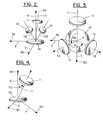
- the three reaction wheels are located or oriented to maintain full three axis attitude control of the spacecraft and gyroscopic stiffness should the momentum wheel fail. If sized similarly, each reaction wheel should provide at least one third of the momentum of wheel 10; if sized differently, the three reaction wheels together should provide momentum at least as great as that of the wheel 10 if gyroscopic stiffness redundancy is desired. Examining Figures 1-4, one can follow the placement of the reaction wheels 11, 12 and 13 with the following description. Begin with all three reaction wheels in the same orientation as the momentum wheel 10, that is, with all of their spin axes aligned or coincident. This provides the redundancy for momentum stiffness.
- the wheels are tilted with respect to the y axis (see Figure 2). Then, leaving the first reaction wheel 11 where it is, the other two reaction wheels 12, 13 are moved around the x axis (indicated as a point in Figure 3) to provide control about the z axis (the z axis is defined mathematically as x cross y to provide an orthogonal set of axes according to the right hand rule). In this manner, full three axis attitude control of the spacecraft is assured in all three axes. If wheel 10 becomes inoperative, then wheels 11, 12 and 13 can be spun up together to maintain the momentum stiffness on the x axis that was lost with wheel 10 spinning down.
- wheels 12 and 13 can be activated together to provide momentum in the y direction as represented by an arrowhead 30 ( Figures 2 and 3). If wheel 12 fails, wheel 13 can provide momentum in the z direction as represented by an arrowhead 32 ( Figures 2 and 3), and vice versa if wheel 13 fails.
- Table 1 provides an example of the mathematics associated with the location and performance of the wheels, individually, and during failure.
- the reaction wheels 11, 12, 13 are all similarly sized. They could be sized differently with the understanding that their collective momenta would be greater than that of the momentum wheel 10 if full redundancy of gyroscopic stiffness is required; however, understandably, the mathematical relationships would thereby become much more complex.
- the second column indicates the momentum storage capability in the x direction, the direction of gyroscopic stiffness, as represented by an arrowhead 34 ( Figures 2 and 4).
- the first 4 rows (“10", “11”, “12”, “13") indicate the individual contributions of each wheel.
- the spin axis 110 of momentum wheel 10 is aligned in the x direction, therefore, all of its momentum (I 0 ⁇ 0 ) contributes in this direction.
- Reaction wheels 11, 12, and 13 are tilted down somewhat (by 0 1 with respect to the x axis) to provide a momentum storage component in the x direction. Their orientation is illustrated in Figure 4 for reaction wheel 11 and is identical for reaction wheels 12 and 13.
- This angle is the critical angle selected to maintain the gyroscopic stiffness when the momentum wheel fails as indicated in the sixth row ("w/o 10"). This row indicates that all reaction wheels contribute equally to the stiffness through the cosine of 0 1 .
- the third column (“y”) indicates the momentum storage capability in the y direction, that is, perpendicular to axis x, the direction of gyroscopic stiffness.
- the second row (“11") indicates that the first contributor of momentum storage to the y axis is reaction wheel 11. As the reaction wheels are tilted down from the x axis by 0 1 ( Figure 4), the effect of the sine to increase the contribution to axis y changes more rapidly than the effect of the cosine to decrease the contribution to axis x. This means this design can increase control of the y axis without significantly sacrificing its ability to maintain gyroscopic stiffness as indicated in the second column ("x") .
- reaction wheels, 12 and 13 are needed to provide momentum in the z axis, therefore, their spin axes are rotated away from the spin axis 111 of wheel 11 by 0 2 and 0 3 , respectively, in the y-z plane as in Figure 3.
- Examining rows 3 and 4 ("12", "13"), it is seen that the contribution of the reaction wheels 12 and 13 to momentum storage along the y axis is decreased by the cosine of the angles (02 and 03 respectively) in a similar manner that the contribution to momentum storage along the x axis by all three wheels is decreased by the cosine of 0 1 .
- the fourth column (“z”) indicates the momentum storage capability in the z direction, which is perpendicular to both axes x and y following the right hand rule and is the mathematical cross product of x and y.
- the third and fourth rows (“12", “13") indicate the momentum contributions to the z axis by reaction wheels 12 and 13. As the reaction wheels 12 and 13 are located away from the y axis by angles 0 2 and 0 3 , respectively, the effect of the sine increases the momentum contribution to the z axis and the effect of the cosine decreases the momentum contribution to the y axis (see the third column ("y”)). There is no change to the gyroscopic stiffness as indicated in the second column ("x").
- Failure of the second and third reaction wheels 12 and 13 are indicated in rows 8 and 9 ("w/o 12" and "w/o 13").
- the third and second wheels 13 and 12, respectively, provide the backup in the z direction as indicated in the fourth column (“z"). That is, wheel 13 backs up a wheel 12 failure (“w/o 12") and wheel 12 backs up a wheel 13 failure (“w/o 13").
- the present invention provides an active attitude control system for a spacecraft which utilizes four flywheels, at a minimum, which can selectively provide the following options:
Landscapes
- Engineering & Computer Science (AREA)
- Remote Sensing (AREA)
- Chemical & Material Sciences (AREA)
- Combustion & Propulsion (AREA)
- Radar, Positioning & Navigation (AREA)
- Aviation & Aerospace Engineering (AREA)
- Automation & Control Theory (AREA)
- Control Of Position, Course, Altitude, Or Attitude Of Moving Bodies (AREA)
Applications Claiming Priority (2)
| Application Number | Priority Date | Filing Date | Title |
|---|---|---|---|
| US08/679,575 US5826829A (en) | 1996-07-15 | 1996-07-15 | Spacecraft control system with a trihedral momentum bias wheel configuration |
| US679575 | 1996-07-15 |
Publications (2)
| Publication Number | Publication Date |
|---|---|
| EP0819997A2 true EP0819997A2 (de) | 1998-01-21 |
| EP0819997A3 EP0819997A3 (de) | 1998-05-27 |
Family
ID=24727469
Family Applications (1)
| Application Number | Title | Priority Date | Filing Date |
|---|---|---|---|
| EP97305109A Withdrawn EP0819997A3 (de) | 1996-07-15 | 1997-07-10 | Lageregelungssystem für Raumfahrzeuge |
Country Status (3)
| Country | Link |
|---|---|
| US (1) | US5826829A (de) |
| EP (1) | EP0819997A3 (de) |
| JP (1) | JPH1071999A (de) |
Cited By (6)
| Publication number | Priority date | Publication date | Assignee | Title |
|---|---|---|---|---|
| CN103612254A (zh) * | 2013-11-14 | 2014-03-05 | 北京交通大学 | 一种利用惯性轮驱动的载物机器人 |
| CN106240846A (zh) * | 2015-06-15 | 2016-12-21 | 波音公司 | 交通工具姿态控制 |
| CN106586034A (zh) * | 2016-12-20 | 2017-04-26 | 上海微小卫星工程中心 | 卫星旋转部件动静不平衡干扰力矩自补偿方法 |
| FR3046686A1 (fr) * | 2016-01-08 | 2017-07-14 | Centre Nat D'etudes Spatiales (Cnes) | Dispositif de controle d'attitude d'un engin spatial |
| CN108983801A (zh) * | 2018-08-14 | 2018-12-11 | 北京航空航天大学 | 一种基于反作用飞轮动态特性的航天器抗干扰姿控方法 |
| CN113625554A (zh) * | 2021-06-28 | 2021-11-09 | 北京控制工程研究所 | 一种考虑故障情况的反作用轮配置优化方法及系统 |
Families Citing this family (21)
| Publication number | Priority date | Publication date | Assignee | Title |
|---|---|---|---|---|
| US6062512A (en) * | 1997-08-27 | 2000-05-16 | Hughes Electronics Corporation | Wobble and nutation control, and spin stabilization for a spacecraft using momentum conserving devices |
| US6231011B1 (en) | 1998-11-02 | 2001-05-15 | University Of Houston System | Satellite angular momentum control system using magnet-superconductor flywheels |
| DE19924908B4 (de) * | 1999-05-31 | 2008-05-29 | Astrium Gmbh | Verfahren zur dreiachsigen Lagebestimmung für einen niedrig fliegenden Satelliten |
| FR2796172B1 (fr) * | 1999-07-08 | 2001-09-21 | Cit Alcatel | Systeme pour le controle d'un satellite en attitude et procede corespondant |
| FR2800350B1 (fr) * | 1999-10-29 | 2001-12-28 | Matra Marconi Space France | Systeme de gestion d'energie electrique et de controle d'attitude pour satellite |
| US6347262B1 (en) * | 2000-01-05 | 2002-02-12 | Hughes Electronics Corporation | Minimum fuel attitude and nutation controller for spinning spacecraft |
| US6285928B1 (en) | 2000-01-06 | 2001-09-04 | Space Systems/Loral, Inc. | Onboard attitude control using reaction wheels |
| FR2803578B1 (fr) * | 2000-01-10 | 2002-04-05 | Cit Alcatel | Dispositif et procede de stockage d'energie et vehicule spatial comportant un tel dispositif |
| US6456907B1 (en) * | 2000-01-31 | 2002-09-24 | Space Systems/Loral, Inc. | System and method for limiting the effects of actuator saturation to certain body axes of a spacecraft |
| ES2188404B1 (es) * | 2001-10-17 | 2004-10-16 | Ingenieria, Diseño Y Analisis, S.L. | Actuador giroscopico. |
| US6758444B1 (en) * | 2002-12-30 | 2004-07-06 | Honeywell International Inc. | Momentum control system and method |
| US7370530B2 (en) * | 2004-09-01 | 2008-05-13 | Honeywell International Inc. | Package for MEMS devices |
| CN102616386B (zh) * | 2012-03-29 | 2014-04-02 | 哈尔滨工业大学 | 单轴快速机动航天器飞轮构型的优化方法 |
| CN102799105B (zh) * | 2012-09-06 | 2014-07-02 | 哈尔滨工业大学 | 单轴轮控快速姿态机动卫星的变结构控制模型的建模方法 |
| WO2015003044A1 (en) * | 2013-07-02 | 2015-01-08 | University Of Florida Research Foundation, Inc. | Triple flywheel assembly with attitude jitter minimization |
| CN105159310B (zh) * | 2015-09-07 | 2017-08-08 | 北京航空航天大学 | 一种惯性系航天器姿态控制/角动量管理方法 |
| US10005568B2 (en) * | 2015-11-13 | 2018-06-26 | The Boeing Company | Energy efficient satellite maneuvering |
| CN106094848B (zh) * | 2016-06-14 | 2018-12-04 | 中国科学院数学与系统科学研究院 | 一种无角速度测量对地定向空间站的角动量管理方法 |
| CN105955287B (zh) * | 2016-06-14 | 2019-01-11 | 中国科学院数学与系统科学研究院 | 一种对地定向空间站的姿态控制和角动量管理方法 |
| CN107933968B (zh) * | 2017-11-14 | 2019-06-18 | 中国运载火箭技术研究院 | 一种三飞轮一体化布局装置及其安装调整方法 |
| JP7454410B2 (ja) * | 2020-03-04 | 2024-03-22 | ダブル技研株式会社 | 空中搬送装置 |
Family Cites Families (16)
| Publication number | Priority date | Publication date | Assignee | Title |
|---|---|---|---|---|
| US3591108A (en) * | 1967-01-27 | 1971-07-06 | Rca Corp | Control system for spinning bodies |
| US3940096A (en) * | 1974-11-27 | 1976-02-24 | Rca Corporation | Re-orientation of a spacecraft relative to its angular momentum vector |
| US3999729A (en) * | 1975-03-20 | 1976-12-28 | Rca Corporation | Backup wheel for a three axis reaction wheel spacecraft |
| US4084772A (en) * | 1976-01-28 | 1978-04-18 | Rca Corporation | Roll/yaw body steering for momentum biased spacecraft |
| US4071211A (en) * | 1976-09-23 | 1978-01-31 | Rca Corporation | Momentum biased active three-axis satellite attitude control system |
| US4230294A (en) * | 1979-07-23 | 1980-10-28 | Rca Corporation | Closed loop roll control for momentum biased satellites |
| US4825716A (en) * | 1987-11-13 | 1989-05-02 | Honeywell, Inc. | Single gimbal control moment gyroscope skewed array mounting arrangement |
| US4916622A (en) * | 1988-06-16 | 1990-04-10 | General Electric Company | Attitude control system |
| DE3941654A1 (de) * | 1989-12-16 | 1991-06-20 | Teldix Gmbh | Verfahren zur lageregelung von satelliten |
| US5058835A (en) * | 1990-06-11 | 1991-10-22 | General Electric Company | Wheel speed management control system for spacecraft |
| FR2670746B1 (fr) * | 1990-12-21 | 1993-04-16 | Aerospatiale | Systeme de controle d'attitude pour satellite 3-axes,; notamment pour satellite d'observation. |
| FR2678894B1 (fr) * | 1991-07-09 | 1993-11-19 | Aerospatiale Ste Nationale Indle | Procede et dispositif de controle d'attitude en roulis-lacet d'un satellite a direction unique d'actionnement continu. |
| US5201833A (en) * | 1991-07-19 | 1993-04-13 | General Electric Company | Attitude control system with reaction wheel friction compensation |
| US5205518A (en) * | 1991-11-25 | 1993-04-27 | General Electric Co. | Gyroless yaw control system for a three axis stabilized, zero-momentum spacecraft |
| US5248118A (en) * | 1992-05-13 | 1993-09-28 | General Electric Co. | Spacecraft attitude control system with reaction wheel bearing protection |
| US5308024A (en) * | 1992-07-20 | 1994-05-03 | General Electric Co. | Disturbance torque compensated three axis yaw control system |
-
1996
- 1996-07-15 US US08/679,575 patent/US5826829A/en not_active Expired - Lifetime
-
1997
- 1997-07-07 JP JP9181516A patent/JPH1071999A/ja active Pending
- 1997-07-10 EP EP97305109A patent/EP0819997A3/de not_active Withdrawn
Cited By (9)
| Publication number | Priority date | Publication date | Assignee | Title |
|---|---|---|---|---|
| CN103612254A (zh) * | 2013-11-14 | 2014-03-05 | 北京交通大学 | 一种利用惯性轮驱动的载物机器人 |
| CN103612254B (zh) * | 2013-11-14 | 2015-12-09 | 北京交通大学 | 一种利用惯性轮驱动的载物机器人 |
| CN106240846A (zh) * | 2015-06-15 | 2016-12-21 | 波音公司 | 交通工具姿态控制 |
| CN106240846B (zh) * | 2015-06-15 | 2021-10-01 | 波音公司 | 交通工具姿态控制 |
| FR3046686A1 (fr) * | 2016-01-08 | 2017-07-14 | Centre Nat D'etudes Spatiales (Cnes) | Dispositif de controle d'attitude d'un engin spatial |
| CN106586034A (zh) * | 2016-12-20 | 2017-04-26 | 上海微小卫星工程中心 | 卫星旋转部件动静不平衡干扰力矩自补偿方法 |
| CN108983801A (zh) * | 2018-08-14 | 2018-12-11 | 北京航空航天大学 | 一种基于反作用飞轮动态特性的航天器抗干扰姿控方法 |
| CN113625554A (zh) * | 2021-06-28 | 2021-11-09 | 北京控制工程研究所 | 一种考虑故障情况的反作用轮配置优化方法及系统 |
| CN113625554B (zh) * | 2021-06-28 | 2023-06-30 | 北京控制工程研究所 | 一种考虑故障情况的反作用轮配置优化方法及系统 |
Also Published As
| Publication number | Publication date |
|---|---|
| JPH1071999A (ja) | 1998-03-17 |
| EP0819997A3 (de) | 1998-05-27 |
| US5826829A (en) | 1998-10-27 |
Similar Documents
| Publication | Publication Date | Title |
|---|---|---|
| US5826829A (en) | Spacecraft control system with a trihedral momentum bias wheel configuration | |
| US4230294A (en) | Closed loop roll control for momentum biased satellites | |
| US6481672B1 (en) | Gimbaled thruster control system | |
| EP0769736B1 (de) | Methode zur Steuerung der Lage eines durch Eigenrotation stabilisierten Satelliten in einer geneigten Umlaufbahn | |
| US5349532A (en) | Spacecraft attitude control and momentum unloading using gimballed and throttled thrusters | |
| US4911385A (en) | Attitude pointing error correction system and method for geosynchronous satellites | |
| CA2338459A1 (en) | System and method for spacecraft attitude control | |
| US20080315039A1 (en) | System and methods for space vehicle torque balancing | |
| US5738309A (en) | Single axis correction for orbit inclination | |
| US7823836B2 (en) | Optimal sun safe attitude for satellite ground tracking | |
| US6360996B1 (en) | Steering control for skewed scissors pair CMG clusters | |
| EP0743249A1 (de) | Universelles Lageregelungssystem für Raumfahrzeug | |
| JP7576628B2 (ja) | 太陽エネルギーを追跡するシステム | |
| US6311931B1 (en) | Bi-directional momentum bias spacecraft attitude control | |
| US6481671B1 (en) | Spacecraft sunshield for use in performing solar torque balancing | |
| CN87105637A (zh) | 空间飞行器加速度计自动校准 | |
| CA1114209A (en) | Orientation of momentum stabilized vehicles | |
| EP0958170A1 (de) | Lagerregelungssystem eines raumfahrzeuges bei verwendung von niedrigschubdüsen | |
| Tyc et al. | Gyrowheel™-An Innovative New Actuator/Sensor for 3-axis Spacecraft Attitude Control | |
| US6550721B2 (en) | Safing mode for high momentum states in body stabilized spacecraft | |
| EP1697212B1 (de) | Dynamische cmg-anordnung und verfahren | |
| Chubb et al. | Flight performance of skylab attitude and pointing control system | |
| US6682019B2 (en) | Minimum energy wheel configurations for energy storage and attitude control | |
| US11827382B2 (en) | Dayside-only roll steering | |
| Chen et al. | Combined attitude control of small satellite using one flywheel and magnetic torquers |
Legal Events
| Date | Code | Title | Description |
|---|---|---|---|
| PUAI | Public reference made under article 153(3) epc to a published international application that has entered the european phase |
Free format text: ORIGINAL CODE: 0009012 |
|
| AK | Designated contracting states |
Kind code of ref document: A2 Designated state(s): DE FR GB IT |
|
| PUAL | Search report despatched |
Free format text: ORIGINAL CODE: 0009013 |
|
| AK | Designated contracting states |
Kind code of ref document: A3 Designated state(s): AT BE CH DE DK ES FI FR GB GR IE IT LI LU MC NL PT SE |
|
| 17P | Request for examination filed |
Effective date: 19980601 |
|
| AKX | Designation fees paid |
Free format text: DE FR GB IT |
|
| RBV | Designated contracting states (corrected) |
Designated state(s): DE FR GB IT |
|
| RAP3 | Party data changed (applicant data changed or rights of an application transferred) |
Owner name: SPACE SYSTEMS / LORAL, INC. |
|
| 17Q | First examination report despatched |
Effective date: 20000225 |
|
| STAA | Information on the status of an ep patent application or granted ep patent |
Free format text: STATUS: THE APPLICATION IS DEEMED TO BE WITHDRAWN |
|
| 18D | Application deemed to be withdrawn |
Effective date: 20001107 |